Frontiers in Heat and Mass Transfer (FHMT), 4, 013001 (2013) DOI: 10.5098/hmt.v4.1.3001
Global Digital Central ISSN: 2151-8629
1
Frontiers in Heat and Mass Transfer
Available at www.ThermalFluidsCentral.org
FUNDAMENTALS AND APPLICATIONS OF NEAR-FIELD
RADIATIVE ENERGY TRANSFER
Keunhan Parka,∗and Zhuomin Zhangb a
Department of Mechanical, Industrial and Systems Engineering, University of Rhode Island, Kingston, RI 02881, USA
b
G.W. Woodruff School of Mechanical Engineering, Georgia Institute of Technology, Atlanta, GA 30332-0405, USA
ABSTRACT
This article reviews the recent advances in near-field radiative energy transfer, particularly in its fundamentals and applications. When the geometrical features of radiating objects or their separating distances fall into the sub-wavelength range, near-field phenomena such as photon tunneling and surface polaritons begin to play a key role in energy transfer. The resulting heat transfer rate can greatly exceed the blackbody radiation limit by several orders magnitude. This astonishing feature cannot be conveyed by the conventional theory of thermal radiation, generating strong demands in fundamental research that can address thermal radiation in the near field. Important breakthroughs of near-field thermal radiation are presented here, covering from the essential physics that will help better understand the basics of near-field thermal radiation to the most recent theoretical as well as experimental findings that will further promote the fundamental understanding. Applications of near-field thermal radiation in various fields are also discussed, including the radiative property manipulation, near-field thermophotovoltaics, nanoinstrumentation and nanomanufacturing, and thermal rectification.
Keywords:thermal radiation, micro/nanoscale, radiative properties, thermophotovoltaics, nanoinstrumentation, nanomanufacturing
1. INTRODUCTION
Conventionally, the theory of thermal radiation is based on the concept of blackbody, cast by Gustav Kirchhoff in 1860. A blackbody absorbs all energy of the radiation rays reaching it geometrically. Among all objects at the same temperature with the same geometry, a blackbody emits the largest amount of energy when measured in the same angular and spectral ranges. As such, the Stefan-Boltzmann law and Planck’s law provide descriptions of the total and spectral characteristics of blackbodies. Thermal emission from real materials can be described by comparison with that emitted by a blackbody at the same temperature using a property called emissivity (also called emittance). Although care should be taken with regards to the proper definition of emissivity (spectral, total, directional, individual polarization versus polarization averaged, etc.) (Howellet al.,2010;Modest,2003;Zhang,2007), the emissivity should be always smaller than unity in conventional thermal radiation: that is, thermal emission from real materials is always smaller than that from the blackbody in the far-field regime.
Conventional radiative transfer approaches are often not applicable when the geometric features or distances are smaller than the characteris-tic wavelength of thermal radiation based on the Wien’s displacement law (Zhang and Wang, 2012). Planck(1914) noted that the spectral distribution of blackbody radiation is derived based on the assumption that the geometric dimensions of the enclosure (also called a blackbody cavity) are much greater than the characteristic wavelength of thermal radiation. This condition makes Planck’s law only applicable in the far
∗
Corresponding author. Email: kpark@egr.uri.edu
DOI: 10.5098/hmt.v4.1.3001 ISSN: 2151-8629 (Fu and Zhang,2009).
Near-field radiation holds promise for applications in energy sys-tems, nanofabrication and near-field imaging. Rapidly depleting reserves of fossil fuels and the concern of the global warming have placed a great demand of alternative power generation technologies. One of such technology is a thermophotovoltaic (TPV) system, which operates on the principle similar to that of solar cells (but with a lower bandgap) to generate electricity from thermal emission. A possible method of improving the performance of TPV systems is to employ near-field thermal radiation for the energy conversion (Basu et al., 2007). However, large near-field thermal radiation is not always favorable in some energy conversion systems: as revealed by Dillner (2008), near-field thermal radiation needs to be suppressed to increase the thermoelectric energy conversion efficiency of thermotunneling devices. Besides the energy conversion, near-field thermal radiation has also been used for imaging beyond the diffraction limit (De Wilde et al., 2006; Kittelet al.,2005). Furthermore, the concept of using near-field radiation as thermal rectifier has also been suggested (Otey et al., 2010; Basu and Francoeur,2011a). Limiting the magnitude of near-field radiation is critical for improving the performance of thermal tunneling devices (Dillner,2008). Another important application of near-field radiation is in the field of nanomanufacturing. Enhanced transmission of metallic films perforated with subwavelength holes stirred the interest in studying light transmission through nanostructures. Nanolithography techniques based on the surface plasmon waves have been demonstrated for patterning structures of less than 50 nm (Liu et al., 2005; Wang et al., 2006). Furthermore, nanoscale direct writing has also been demonstrated using near-field optics coupled with femtosecond laser (Grigoropouloset al., 2007).
This review article provides a thorough review of near-field thermal radiation, covering the essential physics of fluctuational electromag-netism along with recent advances in fundamentals and applications of near-field thermal radiation. The remaining sections are organized as follows. Section 2 focuses on the essential physics of near-field thermal radiation by introducing the fluctuation-dissipation theorem, Dyadic Green’s function, dielectric functions, and surface polaritons. Recent advances on the fundamental research of near-field thermal radiation are discussed in the following sections. Starting from near-field radiative heat transfer between two semi-infinite media, Section 3 discusses the upper limit of near-field radiative heat flux and the extremely small penetration depth of near-field thermal radiation, as well as energy streamlines – a novel way to elucidate the near-field energy propagation between semi-infinite media and multilayered structures. Near-field thermal radiation in other geometries, such as sphere and sphere-flat surface, and between emerging nanomaterials is covered in Section 4, followed by the discussion of experimental observations of near-field radiative heat transfer in Section 5. Section 6 looks into the applications of near-field thermal radiation, including the manipulation of radiative properties, near-field thermophotovoltaics, tip-based engineering, and thermal rectification. In conclusion, a brief summary on the recent progresses in fundamentally understanding and engineering near-field thermal radiation is provided along with remarks on future research opportunities and challenges of the field.
2. ESSENTIAL PHYSICS OF NEAR-FIELD THERMAL RADIATION
2.1. Fluctuation-Dissipation Theorem
Thermal radiation between solids is traditionally treated as a surface phenomenon with the concept of emissivity, reflectivity and absorptivity of the surfaces. Radiation heat transfer in a participating medium is thus analyzed using ray optics, leading to the development of the radiative transfer equation (RTE) that considers emission, absorption, and scattering of thermally emitted rays in the medium (Howellet al.,
2010). Although RTE can determine the radiation distribution within the medium by computing the intensity along the propagation of ra-diation, this phenomenological equation does not fully account for the fundamentals of thermal emission and breaks down when wave interference and diffraction become important. To speculate the origin of thermal radiation, Rytov and his co-workers (1987) combined the fluctuation-dissipation theorem and Maxwell’s equations to establish the fluctuational electrodynamics. According to the fluctuation-dissipation theorem, thermal radiation is essentially EM waves emitted from the fluctuating currents due to the random thermal motion of charges, known as thermally induced dipoles, in a medium. Thus the propagation of thermal radiation and its interaction with matter can be fully described in the framework of the fluctuational electrodynamics, in both the far-field and near-field regimes.
When a material is in thermal equilibrium at temperatureT, charges in the material – electrons in metals or ions in polar crystals – are subject to random thermal motions and generate fluctuating electric currents. The fluctuating electric density j(x, t), or j(x, ω) in the frequency domain, can be implemented in Maxwell’s equations as an external source to make the equations stochastic. The key issue in calculating thermally induced, fluctuating EM waves is then how to determine the statistical properties of these random sources. According to the fluctuation-dissipation theorem (FDT), while the fluctuating electric density is averaged to zero (i.e.,hjm(x, ω)i = 0) due to its random
nature, the ensemble average of its cross-spectral spatial correlation function is nonzero and expressed as (Joulainet al.,2005):
jm(x0, ω)jn∗(x
00
, ω0)
= 4
πωε0Im(ε(ω))δmnδ(x
0
−x00)Θ(ω, T)δ(ω−ω0) (1)
where h i represents ensemble averaging, and ∗denotes the complex conjugate. In Eq. (1),ε0is the electrical permittivity of the free space,
jm andjn (m, n= 1, 2, or 3) stands for thex,y, orz component of
j, δmnis the Kronecker delta, andδ(x0−x00)andδ(ω−ω0)are the
Dirac delta function. Θ(ω, T)is the mean energy of a Planck oscillator at the frequencyωin thermal equilibrium at temperatureTand is given byΘ(ω, T) =~ω/[exp(~ω/kBT)−1], where~is the Planck constant divided by 2πand kBis the Boltzmann constant. Since only positive values of frequencies are considered here, a factor of 4 has been included in Eq. (1) to consistently use the conventional definitions of the spectral energy density and the Poynting vector (Fu and Zhang,2006).
2.2. Dyadic Green’s Function
For prescribed geometric conditions and temperature, Maxwell’s equa-tions need to be solved in order to obtain the electric and magnetic field distributions. This can be done with the help of the dyadic Green’s function, which makes the formulations simple and compact. With the assistance of the dyadic Green’s functionGe(x,x0, ω), the induced
electric and magnetic fields due to the fluctuating current density can be expressed respectively in the frequency domain as volume integrations:
E(x, ω) =iωµ0
Z
V
Ge(x,x
0
, ω)·j(x0, ω)dx0 (2)
H(x, ω) =
Z
V
Gh(x,x
0
, ω)·j(x0, ω)dx0 (3)
whereGh(x,x0, ω) =∇ ×Ge(x,x0, ω)is the magnetic dyadic Green’s
function, µ0 is the magnetic permeability of vacuum, and the integral is over the region V that contains the fluctuating sources. The dyadic Green’s function,Ge(x,x0, ω)is essentially a spatial transfer function
Frontiers in Heat and Mass Transfer (FHMT), 4, 013001 (2013) DOI: 10.5098/hmt.v4.1.3001
Global Digital Central ISSN: 2151-8629
Fig. 1Schematic of near-field radiative heat transfer between two closely spaced semi-infinite plates, at temperaturesT1andT2, separated by a vacuum gapd.
flux is given by (Basuet al.,2009)
hS(x, ω)i=
Z∞
0 1 2
Re[E(x, ω0)×H∗(x, ω0)]
dω0 (4)
where S is the spectral Poynting vector, ω (and ω0) is the angular frequency. In order to compute the spectral Poynting vector atx, we should compute the cross-spectral density of electric and magnetic field vectors Ei(x, ω) and Hj(x, ω0) . The cross-spectral density can be
written as
Ei(x, ω)H
∗
j(x, ω
0
)
=iωµ0
Z
V
dx0 Z
V
dx00
Ge,im(x,x
0
, ω)Gh,jn(x,x
00
, ω0)
jm(x
0
, ω)jn∗(x
00
, ω0) (5) With the relationship between the fluctuating current densities and the temperature of the emitting medium being established through Eq. (1), the spectral radiative heat flux can be calculated using Eq. (5) once the dyadic electric Green’s function, Ge(x,x0, ω) is obtained. Since the
dyadic Green’s function depends on the geometry of the physical system, the following sections will briefly describe the dyadic Green’s functions for two representative structures, i.e., for two semi-infinite media and multilayered media.
Two semi-infinite media: Let’s consider near-field thermal radiation between two semi-infinite media separated by a vacuum gap (or a dielectric medium) of widthd, when they are in thermal equilibrium at temperatures T1 and T2, respectively, where T1 > T2. Both media are nonmagnetic, isotropic, and homogeneous, and surfaces are parallel and smooth. As illustrated in Fig. 1, dipoles in the media are in random motions, radiating space-time dependent fluctuating electric field, E(x, t). Cylindrical coordinate system is used so that the space variable x = r+z, withr-direction being parallel to the interface andz-direction perpendicular to the interface. βandγj refer to ther
-component andz-component of the wavevectorkj, respectively. Thus,
kj =βˆr+γjˆzandkj2 =β2+γ2j, forj= 0, 1, and 2. The magnitude
ofkjis related to the dielectric functionεjbyk0=ω/c,k1=
√
ε1ω/c, andk2=
√
ε2ω/c, withcbeing the speed of light in vacuum andε1and
ε2 being the dielectric functions (or relative permittivity) of medium 1 and 2, respectively. For the described two semi-infinite media, the dyadic Green’s function takes the following form (Fu and Zhang,2006;Joulain
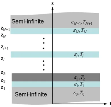
Fig. 2 Schematic of a multilayered thin-film structure for Green’s function analysis. Each of the films may be at a different temperature.
et al.,2005)
Ge(x,x0, ω) =
Z ∞
0
i
4πγ1
(ˆsts12ˆs+pˆ2tp12pˆ1)e
i(γ2z−γ1z0)
eiβ(r−r0)βdβ (6)
wherex=rˆr+zˆzandx0=r0ˆr+z0ˆz. The unit vectors areˆs= ˆr׈zand ˆ
p1(2) = βˆz−γ1(2)ˆr
/k1. Note thatts12andt p
12are the transmission coefficients from medium 1 to medium 2 for s- and p-polarizations, respectively, given by Airy’s formula (Zhang,2007). Provided thatts
12 and tp12take into account multiple reflections in the vacuum layer, the dyadic Green’s function describes the transfer of the electromagnetic fields through propagating waves (i.e.,β < kj) and evanescent waves
(i.e.,β > kj), from a point source atx0to a receiving point atx.
Multilayered media: Dyadic Green’s function for multilayered struc-tures has been extensively used for calculating microwave thermal emis-sion from layered media (Tsanget al.,1974), thermal emission from 1-D photonic crystals (Narayanaswamy and Chen,2005), power generation in near-field TPV systems (Park et al., 2008), and near-field energy transfer between bodies with thin film coatings (Francoeuret al.,2008; Fu and Tan, 2009). Figure 2shows the schematic of a multilayered structure containingNthin films sandwiched between two semi-infinite half spaces. Properties of the layers are different and are assumed to vary only in the z-direction. The layers can be metallic, dielectric or even be a vacuum gap and can have a temperature gradient across them. The dyadic Green’s function between any two layerssandlin Fig.2is given by (Parket al.,2008)
Ge(x,x
0
, ω) = i 4π
Z
βdβ γs
F(β)eiβ(r−r0) (7) where
F(β) =Aei(γlz−γsz0)ˆe+
lˆe
+
s +Be
i(−γlz−γsz0)ˆe−
l ˆe
+
s+
Cei(γlz+γsz0)ˆe+
l ˆe
−
s +De
i(−γlz+γsz0)ˆe−
l ˆe
−
s (8)
Here, the subscriptsdenotes a source layer andlis the receiving layer. Note thatˆe+andeˆ−
are two unit vectors, which are given byˆe+l = ˆe−l = ˆ
r׈zfors-polarization andˆe±l = (βˆz∓γlˆr)/klforp-polarization,
DOI: 10.5098/hmt.v4.1.3001 ISSN: 2151-8629 There are four terms in the expression ofF(β)because EM waves
in each layer can be decomposed into upward and downward components due to multiple reflections at each interface. The first two terms account for the upward and downward waves in thel-th layer, respectively, which are induced by the upward waves in the source medium. Likewise, the last two terms denote the two waves inl-th layer due to the downward waves in the source medium (Tsanget al.,2004). It should be pointed out that the terms havingˆe−s become zero if the source is in the bottom
semi-infinite medium while thel-th layer is located above, and the terms havingeˆ−l become zero if thel-th layer is the top semi-infinite medium or if there is free emission from multilayered structures. When both the source and receiver layers are semi-infinite, Eq. (7) will reduce to Eq. (6).
2.3. Dielectric Functions
Besides the fluctuation-dissipation theorem and dyadic Green’s function, the dielectric function of materials should also be discussed to better understand near-field thermal radiation and its interactions with materials. If nonlinear optical effects are ignored, the polarizationPis related to the electric field asP(x, ω) = ε0χe(x, ω)E(x, ω), whereχe(x, ω)is the electric susceptibility of the medium andε0 is the permittivity of vacuum (Griffiths,2012). The electric susceptibility indicates the degree of polarization of a dielectric material in response to the incident electric field, depending on the microscopic structure of the medium. The electric displacement vectorDcan be expressed as
D(x, ω) =ε(ω)E(x, ω) (9) where ε(ω) is the dielectric function or relative permittivity of the medium and is related with the electric susceptibility asε(ω) =ε0[1+
χe(ω)]. It should be noted that the spatial dependence term in the susceptibility and the relative permittivity drops out under the local assumption. This local assumption remains valid for near-field thermal radiation unless the vacuum gap is extremely small (less than 1 nm distance). In the extreme proximity, the dielectric function becomes nonlocal and its wavevector dependence must be considered (Joulain, 2008). Recently, Chapuiset al.(2008a) calculated the near-field heat transfer between two semi-infinite gold plates using non-local dielectric function models and compared their results with the heat flux calculated using the Drude model for gold. They found that the non-local dielectric function saturates the near-field thermal radiation as the vacuum gap approaches zero, whilst local dielectric function erroneously diverges the thermal radiation .
Equation (9) represents the displacement of charges inside the material upon the incidence of electric waves. Thus the dielectric function is the key property in understanding the light-matter interactions, and needs to be further discussed. Under the local assumption, the following sections will discuss two models of the dielectric function, the Drude model for metals (and semiconductors) and the Lorentz model for dielectrics.
Drude model for metals and semiconductors: The Drude model describes the frequency-dependent conductivity of metals and can also be extended to free-carriers in semiconductors. In a metal, electrons in the outermost orbits are “free” to move in accordance with the external electric field. The dielectric function of a metal can be modeled by considering the electron movement under the electric field and is related to the conductivity by (Zhang,2007)
ε(ω) =ε0+iε00= (n+iκ)2=ε∞−
σ0/τ ε0(ω2+iω/τ)
(10)
whereε∞accounts for high-frequency contributions,τ is the relaxation time (inverse of scattering rate),σ0is the dc conductivity, andnandκ are the refractive index and extinction coefficient, respectively. Based on Eq. (10), the real and imaginary parts of the dielectric function can be
expressed asε0 = n2−κ2 andε00
= 2nκ, respectively. The plasma frequency is defined as ωp =
p
σ0/(τ ε0), which is in the ultraviolet region for most metals. Whenω < ωp,nbecomes smaller thanκand
ε0becomes negative. At very low frequencies (ωτ 1), the real part of the dielectric function is much smaller than the imaginary part, and therefore,n≈κ. Generally speaking, metals become highly reflective in the visible and infrared regions.
Lorentz model for dielectrics: Unlike metals, the electrons in a di-electric are bound to molecules and cannot move freely. In contrast to free electrons, bound charges experience a restoring force given by the spring constant in addition to the damping force given by the scattering rate. There exist different kinds of oscillators in a real material, such as bound electrons or lattice ions. The response of a single-charge oscillator to a time-harmonic electric field can be extended to a collection of oscillators. Assuming N types of oscillators in a dielectric, the corresponding dielectric function can be given as (Zhang,2007)
ε(ω) =ε∞+
N
X
j
ω2p,j
ω2
0,j−ω2−iω/τj
(11)
where ωp,j, ω0,j, and τj may be viewed as the plasma frequency,
resonance frequency and the relaxation time of the j-th oscillator, respectively. Since the parameters for the Lorentz model are more difficult to be modeled as compared to those for the Drude model, they are considered as adjustable parameters that are determined from fitting. It can be observed from Eq. (11) that for frequencies far greater or lower than the resonance frequency, the extinction coefficient becomes negligible and the dielectrics are completely transparent. Absorption is appreciable only when an interval (i.e., 1/τj) is around the resonance
frequency. Therefore, the dielectric becomes highly reflective near the resonance frequency, and the radiation inside the material is rapidly attenuated or dissipated. The spectral region with a large imaginary part of the dielectric function is also called the region of resonance absorption.
2.4. Surface Plasmon (or Phonon) Polaritons
Another radiative phenomenon that is worthwhile to discuss here is the optical plasmon (or phonon) polariton. Plasmons are quasiparticles associated with oscillations of plasma, which is a collection of charged particles such as electrons in a metal or semiconductor (Raether,1988). Plasmons are longitudinal excitations of electron charges that can occur either in the bulk or at the interface. The field associated with a plasmon is confined near the surface, while the amplitude decays away from the interface. Such a wave propagates along the surface, and it is called a surface electromagnetic wave. Surface plasmons can be excited by electromagnetic waves and are important for the study of optical properties of metallic materials, especially near the plasma frequency, which usually lies in the ultraviolet.
In addition to the requirement of evanescent waves on both sides of the interface, the polariton dispersion relations given below must be satisfied (Raether,1988;Parket al.,2005):
k1z
ε1 +k2z
ε2
= 0 for TM waves (12)
k1z
µ1 +k2z
µ2
= 0 for TE waves (13)
Frontiers in Heat and Mass Transfer (FHMT), 4, 013001 (2013) DOI: 10.5098/hmt.v4.1.3001
Global Digital Central ISSN: 2151-8629 polariton (SPhP). On the other hand, magnetic materials having negative
permeability are necessary to excite a surface polariton for a TE wave. Some metamaterials can exhibit negative permeability in the optical frequencies, and negative index materials exhibit simultaneously negative permittivity and permeability in the same frequency region. Therefore, both TE and TM waves may excite SPPs with negative index materials (Parket al.,2005) or with bilayer materials of alternating negativeεand
µ, the so-called single negative materials (Fuet al.,2005).
The condition for the excitation of surface polaritons is that the denominator of Fresnel’s reflection coefficient be zero. A pole in the reflection coefficient is an indication of a resonance. Taking a TM wave for example, one can solve Eq. (12) to obtain (Zhang,2007)
kx=
ω c
s
µ1/ε1−µ2/ε2 1/ε2
1−1/ε22
(14)
This equation is called the polariton dispersion relation, which relates the frequency with the parallel component of the wavevector. For nonmagnetic materials, it becomes
kx=
ω c
r
ε1ε2
ε1+ε2
(15)
One should bear in mind that the permittivities are in general functions of the frequency. For a metal with a negative real permittivity, the normal component of the wavevector is purely imaginary for any realkx, because
(µεω2)/c2 <0. Thus, evanescent waves exist in metals regardless of the angle of incidence.
The requirement of evanescent waves on both sides of the interface prohibits the coupling of propagating waves to the surface polaritons. Figure3qualitatively shows a dispersion curve of surface polaritons from Eq. (15) along with the dispersion line of the light propagating in a
n
pn
d✓
(a) A metal-coated prism coupler
!
=
ck
x/n
d!
=
ck
x
/n
p
!
=
ck
x/
(
n
psin✓
)
k
x
(b) Dispersion relationFig. 3(a) Schematic diagrams of a metal-coated prism surface polariton coupler and (b) dispersion curves.
dielectric having a refractive index nd, suggesting that the propagating light cannot excite the surface polariton. In order to couple propagating light with surface polaritons, we critically need a coupler that can shift the dispersion line of the light to match the parallel (or in-plane) wavevector component to that of the surface polaritons (Raether,1988). Two conventional surface polariton couplers being widely accepted are a metal-coated prism and a metallic grating structure, whose configurations and mechanisms of light-SP(h)P coupling are schematically illustrated in Figs. 3and 4. For a metal-coated prism coupler (or Kretschmann coupler), the in-plane wavevector of the incident light becomes kx =
npk0sinθ, wherenpis the refractive index of the prism andk0=ω/cis the propagating wavevector in vacuum, when the light is incident on the metallic thin film of the prism side with the incidence angleθ. Owing to the large refractive index of the prism, the dispersion line of the incident light shifts to a greaterkx, or to the right in Fig. 3(b), to intersect with
the dispersion curve for the surface polariton: A metal-coated prism can excite the surface polariton.
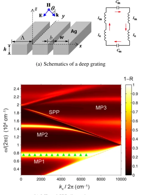
When the light is incident on the grating structure as shown in Fig. 4(a), the Bloch-Floquet condition becomeskx,j = kx + 2πj/Λ,
where j is the diffraction order and Λis the grating period. The in-plane wavevector of the diffracted light can increase by a factor of2πj/Λ depending on the diffraction order, shifting the light dispersion to couple with the SPP. It should be noted that the grating coupler can excite multiple surface polaritons even at the normal incidence. Figure 4(b)
shows the reduced dispersion relation for a binary grating made of Ag withΛ = 1.7µm (Zhang,2007). The dispersion curves (dash-dotted
(a) A metal grating coupler Int J Thermophys
Fig. 2 Dispersion relation of SPP as manifested by an Ag grating [19]. Note thatkx=(ω/c)sinθ
Fig. 3 Calculated reflectance for the TM wave from a shallow grating near the surface of silver [19]
2.3 Wood’s Anomaly
Wood’s anomaly affects radiative properties and causes abrupt changes in the
reflec-tance, transmitreflec-tance, and absorptance spectra [
37
]. Wood’s anomaly occurs when a
diffraction order emerges or disappears at the grazing angle. The transmittance through
a 1D slit array can be either enhanced or suppressed due to Wood’s anomaly. Since
Wood’s anomaly occurs as a result of diffraction, both polarizations may exhibit such
an anomaly. For shallow gratings when the plane of incidence is perpendicular to
the grooves, however, Wood’s anomaly is not obvious for TE waves, and thus, initial
studies only dealt with the anomaly for TM waves [
38
].
123
(b) Dispersion relation
Fig. 4(a) Schematic diagrams of a metal grating surface polariton coupler and (b) Dispersion relation of SPP as manifested by an Ag grating (Zhang,2007). Note thatkx= (ω/c) sinθ.
DOI: 10.5098/hmt.v4.1.3001 ISSN: 2151-8629 lines) are folded. The solid lines correspond to an incidence angle of
30◦ and are also folded. The intersections identify the location where SPPs can be excited for a TM wave incidence, when the magnetic field is parallel to the grooves.
The excitation of surface polaritons makes a significant effect on near-field thermal radiation. As briefly mentioned in the introduction, the enhancement of heat transfer rate in near-field thermal radiation is because photon tunneling enables evanescent EM waves to carry radiative energy across the vacuum gap. Among the involved evanescent waves, those that match with the dispersion relation of the surface polariton will resonantly enhance the absorption of the evanescent EM fields. Thus near-field radiative heat transfer can be greatly enhanced with the surface polariton excitation. Moreover, surface polaritons play a crucial role in tailoring the spectral and directional radiative properties of materials. For example, coherent thermal emission can be realized by exciting surface polaritons in grating structures and truncated photonic crystals. Further discussion is deferred to later sections
3. NEAR-FIELD RADIATIVE ENERGY TRANSFER BETWEEN TWO SEMI-INFINITE MEDIA
3.1. Formulation of Near-Field Radiation
Consider the structure shown in Fig. 1, where both the emitter and receiver aren-doped silicon. The emitter and receiver are assumed to be at 400 and 300 K, respectively. The dielectric function model of doped Si may be modeled as a combination of Drude term and other contributions (Fu and Zhang, 2006) and the details are described in (Basu et al., 2010a,b). The total heat transfer between two media can be expressed as (Basuet al.,2009)
q00net= 1
π2
Z ∞
0
[Θ(ω, T1)−Θ(ω, T2)]X(ω)dω (16)
whereX(ω) =R∞
0 s(ω, β)dβ. Note that the integration ofs(ω, β)over
ωgives a weighted function to modify the Planck blackbody distribution function. Expression ofs(ω, β)is different for propagating (β < ω/c) and evanescent (β < ω/c) waves,
sprop(ω, β) =
β(1−ρs
01)(1−ρs02) 4|1−rs
01r02s ei2γ0d| 2 +
β(1−ρp01)(1−ρp02) 4|1−rp01r
p 02ei2γ0d|
2 (17)
and,
sevan(ω, β) =
Im(rs01)Im(rs02)βe−2Im(γ0)d |1−rs
01r02s e−2Im(γ0)d|
2 +
Im(r01p)Im(r p 02)βe
−2Im(γ0)d |1−rp01r
p
02e−2Im(γ0)d|
2 (18)
In Eqs. (17) and (18), the first term on the right-hand side refers to the contribution of s-polarization or TE wave, while the second term refers to the contribution of p-polarization or TM wave. Note that
r0sj= (γ0−γj)/(γ0+γj)andr0pj= (εjγ0−γj)/(εjγ0+γj)are the
Fresnel reflection coefficients fors- andp-polarization, respectively, at the interface between vacuum and mediumj(1 or 2). On the other hand,
ρ0j=|r0j|2is the far-field reflectivity at the interface between vacuum
and mediumj. When different doping levels are considered, the location of the peak ins(ω, β)shifts towards higher frequencies with increased doping level.
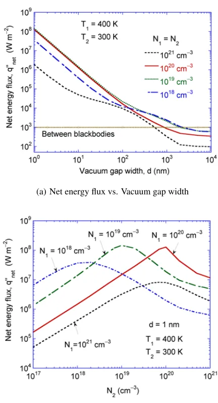
Notice thats(ω, β)is independent of temperature and contains all the information about the material properties as well as the geometry of the emitting media. The predicted radiative heat transfer between two doped Si plates is plotted in Fig. 5(a)as a function of the vacuum gap width (Basuet al.,2010b). Both plates are maintained at the same doping level, which is varied from1018
to1021
cm3. The dotted line with circles is the radiative heat flux between two blackbodies. The net heat flux at
(a) Net energy flux vs. Vacuum gap width
(b) Net energy flux vs. Doping concentration
Fig. 5 Net energy flux between medium 1 (at 400 K) and medium 2 (at 300 K) versus the gap width for Si at different doping levels. The dash-dotted line refers to the net energy transfer between two blackbodies maintained at 400 and 300 K, respectively; and (b) effect of doping on the net energy transfer between two doped Si plates separated by 1 nm vacuum gap (Basuet al.,2010b).
d = 1nm between1019or1020cm3 doped Si plates can exceed that between two blackbodies by five orders of magnitude, because of photon tunneling and surface waves. Increase in the doping level of Si does not always enhance the energy transfer. In fact, the radiative heat transfer is the smallest for 1021 cm3 doped Si plates as compared with other doping levels considered here. Atd >200nm, doping concentrations between1018
and1019
Frontiers in Heat and Mass Transfer (FHMT), 4, 013001 (2013) DOI: 10.5098/hmt.v4.1.3001
Global Digital Central ISSN: 2151-8629 materials can be well explained by surface polaritons. The coupling of
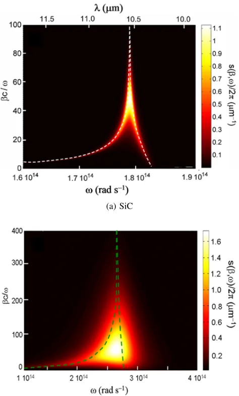
SP(h)Ps allows a significant increase in the function given in Eq. (18) for evanescent waves. Furthermore, for magnetic materials, the enhancement can occur for boths−andp−polarizations, resulting in multiple spectral peaks in near-field radiative transfer (Wanget al.,2009;Joulainet al., 2010; Zheng and Xuan, 2011). It should be noted that for intrinsic Si or dielectric materials without strong phonon absorption bands, the tunneling is limited and saturate at extremely small distances. Also, for good metals, the SPP excitation frequency is too high to significantly enhance thermal radiation unless the distance is less than 1 nm (Wang et al.,2009;Basu and Francoeur,2011b). Figure6illustrates the surface wave effects on the enhancement of near-field thermal radiation by comparing the contour plots ofs(ω, β)/2π for SiC plates separated at 100 nm in Fig.6(a)and for1020cm3n−doped Si plates separated at 10 nm in Fig.6(b). Only TM waves are compared here since the contribution of TE waves is negligibly small. For simplicity,βis normalized with respect toω/c. The brightest color represents the peak value atωm = 1.79×10¹⁴
rad/s andβm = 50ω/cfor SiC, and atωm= 2.67×10¹⁴
(a) SiC
(b) Doped Si with1020cm−3
Fig. 6 Contour plot of s(ω, β)/2π for (a) SiC and (b) n-doped Si for doping concentration of1020 cm−3. Note that the parallel wavevector component is normalized to the frequency. The dashed curves represent the two branches of the surface-polariton dispersion (Lee and Zhang,2008;Basuet al.,2010b).
rad/s andβm = 62ω/cfor doped Si. The contribution of propagating waves (β < ω/c) to the overall heat transfer is negligible. As mentioned earlier, the resonance energy transfer in the near field aroundωmis due to SPhP for SiC and SPP for doped Si, respectively.
The calculated dispersion curves for surface polaritons between two SiC and doped Si plates are also plotted as dashed lines in Figs. 6(a)
and 6(b), respectively. Due to the coupling of surface polaritons at vacuum-SiC and vacuum-doped Si interfaces, there exist two branches of dispersion curves for the p polarization as follows:
Symmetric mode : γ0
ε0 + coth
−iγ0d
2
·γ1
ε1
= 0 (19a)
Asymmetric mode : γ0
ε0 + tanh
−iγ0d
2
·γ1
ε1
= 0 (19b)
The lower-frequency branch corresponds to the symmetric mode, and the higher-frequency branch represents the asymmetric mode (Park et al., 2005). Note that for both doped Si and SiC, the dispersion relation becomes almost flat at ωmax implying that surface polaritons can be excited in a wide range ofβ, being responsible for the enhancement of thermal radiation through photon tunneling (Lee and Zhang,2008).
3.2. Upper Limit of Near-Field Heat Flux
For nonmagnetic materials, when β ω/c (evanescent waves), we haveγ1 ≈ γ2 ≈ γ0 ≈ iβ. As a result, for dielectrics,rs01 andr01s are negligibly small, and the contribution of TE waves can be ignored. Furthermore,rp01≈(ε1−1)/(ε1+ 1)andrp02≈(ε2−1)/(ε2+ 1)are independent ofβ. Hence, Eq. (18) can be simplified as
sevan(ω, β)≈
Im(rp01)Im(r02p)βe−2βd
1−r
p 01r
p 02e−2βd
2 (20)
However, for metals, the contribution from TE waves is more significant whenω/c=β=p
|ε1|ω/c, whereas the contribution from TM waves is more important forβ p
|ε1|ω/c ω/c(Chapuiset al.,2008a). As a result, for metals, heat transfer due to TM waves becomes dominant at very short distances.
Using the relation, Im [(ε−1)/(ε+ 1)] = (2ε00)/|ε+ 1|2, and assuming identical permittivity for both media, the spectral heat flux from 1 to 2 in the limitd→ ∞is given by (Basu and Zhang,2009a)
q00ω,1−2≈
4Θ(ω, T1)
π2d2
Z
∞ξ0
ε002e−2ξξdξ
|(ε+ 1)2−(ε−1)2e−2ξ|2 (21)
whereξ=βd,ξ0=dω/c, andε00is the imaginary part of the dielectric function. As observed from Eq. (21) the heat flux will be inversely proportional tod2 in the proximity limit. This means that the heat flux will diverge as d → 0and its physical significance has been debated among researchers. It should be noted that thed−2 dependence is for contribution from the p−polarized electromagnetic waves only, since the contribution from thes−polarized waves will asymptotically reach a constant asd →0. As the vacuum gap decreases, the energy transfer shifts to large values of the parallel wavevector component. A cutoff in the order of the lattice constant is imposed as the minimum spatial wavelength, which subsequently sets a maximum wavevector component parallel to the interfaces (Volokitin and Persson, 2004). The imposed cutoff limits the number of modes for photon tunneling. Consequently, the radiative heat flux will experience a reduction asd→0.
In order to consider the upper limit of near-field radiative heat flux,
X(ω)shown in Eq. (16) should be modified toX(ω) =Rβc
0 s(ω, β)dβ to take into account the upper limit of the integration. Electrons in solids move in a periodic potential characterized by the Bloch wave, with a maximum wavevector ofπ/aat the edge of the first Brillouin zone. Here,
DOI: 10.5098/hmt.v4.1.3001 ISSN: 2151-8629 parallel to the surface (Volokitin and Persson, 2004). Take a typical
value ofa as 0.5 nm and note that there exists a maximum ofX, i.e.,
Xmax = βc2/8. There exists an upper limit of the near-field radiative
heat flux given by (Basu and Zhang,2009a;Volokitin and Persson,2004)
qmax00 =Xmax
k2B 6~
(T12−T 2 2) =
k2Bβ 2 c 48~
(T12−T 2
2) (22)
for nonmagnetic materials. Note that q00max is the ultimate maximum heat flux and is only achievable whend → 0. It is found that metals with a large imaginary part in the infrared can help reach such a limit at extremely small distances (Pendry,1999). For distances greater than a few nanometers, however, the situation is different. Basu and Zhang (2009a) considered a case in which both the emitter and receiver are assumed to have frequency-independent permittivity in order to identify the expression of the complex dielectric constant that will result in maximum heat flux. It should be noted that such a constant dielectric function cannot exist in reality because of the violation of Causality. WhenX was plotted againstε0 andε00in a 3D plot or a 2D contour for givend(say 10 nm), it was found thatXmaxcorresponds toε0=−1 at which surface waves exist.
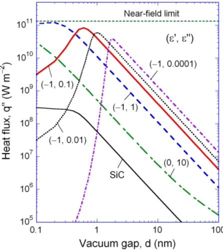
Figure7shows the calculated radiative heat flux between the two media (T1 = 300K andT2 = 0K) as a function of the vacuum gap for different values ofε0andε00(Basu and Zhang,2009a). In most cases,ε0
is fixed at−1. For the sake of comparison, the energy transfer between two SiC plates is also shown in the figure using a frequency-dependent dielectric function. At 300 K, the upper limit of near-field heat flux is 1.4×10¹¹W/m2, which is represented as the dashed horizontal line. The radiation flux between two blackbodies is 459 W/m2, which is several orders of magnitude smaller than near-field radiative transfer. The cutoff inβsets an upper limit on the maximum energy transfer between the two media. Hence, for each of the dielectric functions, there exists an optimal vacuum gap width (dm) that allows the maximum energy transfer. For
ε=−1 +i0.1, it can be seen from Fig.7thatdm= 0.6nm, which also
Fig. 7Plot of radiative heat flux versus gap width for different dielectric functions (Basu and Zhang,2009a). The temperatures of the two media are set to be 300 K and 0 K. The dielectric function is assumed to be frequency independent, except that for SiC for which the Lorentz model at 300 K is used.
maximizesX. The value ofdmdecreases with increasingε00, implying
that the reduction in the energy transfer begins to take place at smaller vacuum gaps. Furthermore, thed−2 dependence in the energy transfer exists only when d > dm. At d > 2 nm, increasingε00 results in
a decrease of the heat flux. When ε = 0 +i10, the radiative heat flux is generally much smaller than those withε0 = −1but will keep increasing towards the upper limit asdunrealistically approaches zero. For the selected dielectric functions withε0 = −1andε00 1, the energy transfer can be orders of magnitude greater than that between SiC plates. This is due to the assumed frequency-independent dielectric function, which results in the excitement of surface waves at almost every frequency. While no such materials can exist, the results provide some hints of appropriate dielectric functions that will result in optimal heat flux at different vacuum gaps. By introducing the cutoff inβ, even for SiC, the d−2 trend ceases to exist atd < 0.6nm. Instead, the near-field radiative transfer reaches a plateau belowd= 0.5nm.Wanget al. (2009) performed a design optimization of the parameters in the Drude model and Lorentz model that can result in the highest near-field radiative flux at given distance and temperatures.
3.3. Penetration Depth in Nanoscale Thermal Radiation
Traditionally, radiation penetration depth in a solid, also called skin depth or photon mean free path, is defined asδλ = λ/(4πκ), whereκis the
extinction coefficient as discussed earlier. A film whose thickness is six times the skin depth can be treated as opaque in most applications. In the optical spectrum, the penetration depth of noble metals is usually10−20 nm. For an evanescent wave, such as that induced under the total internal reflectance setup when light is incident from an optically denser medium to a rarer medium, the skin depth may be defined according to the1/e
attenuation of the field asδ = 1/Im(γ), whereγ(purely imaginary) is the wavevector component perpendicular to the interface in the optically rarer medium. The electric and magnetic fields will decay exponentially and become negligible at a distance greater than about one wavelength. Hence, the skin depth is expected to be several tenths of a wavelength in a dielectric medium. However, in near-field radiation especially when SP(h)Ps are excited, an extremely small skin depth (on the order of the vacuum gapd) may exist even though the dominant wavelengths are in the infrared (Basu and Zhang,2009b). Furthermore, the skin depth is proportional to the separation distance. In essence, the skin depth in near-field thermal radiation is a function of the vacuum gap as well as material properties (Basu and Francoeur,2011b).
For a very small gap, whileωm(see Fig. 6) remains constant as
d decreases, the energy transfer is shifted towards a largerβ, leading to greater near-field enhancement. For β √εjω/c, γj ≈ iβ or
Im(γj) ≈ β. There exists an evanescent wave (in medium 3) whose
amplitude decays according toe−β(z−d). Hence, the skin depth of the field becomes δF ≈ 1/β and the power penetration depth becomes
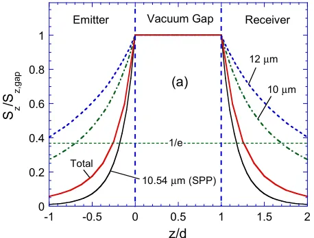
δP≈1/(2β). Using the multilayer Green’s function, thez−component of the Poynting vector, which is proportional to the heat flux, can be calculated both inside the emitter and the receiver. The spectral and total Poynting vector distributions are plotted in Fig. 8for SiC. The ordinate is normalized to the Poynting vector inside the vacuum gap. The energy flux in the emitter increases towards the surface, remains constant in the vacuum gap, and decreases in the receiver away from the surface. When the abscissa isz/d, the results are nearly the same for1nm< d <100 nm. Surprisingly, the distributions are symmetric in the emitter and the receiver. The1/edecay line is shown as the horizontal dashed line so that the penetration depth can be evaluated. Note that the calculated Poynting vector is integrated over allβvalues. As mentioned earlier, when SPP is excited, the energy transfer is pushed towards largeβvalues; hence, the spectral penetration depth has a minimum nearωm.
Frontiers in Heat and Mass Transfer (FHMT), 4, 013001 (2013) DOI: 10.5098/hmt.v4.1.3001
Global Digital Central ISSN: 2151-8629
0 0.2 0.4 0.6 0.8 1
-1 -0.5 0 0.5 1 1.5 2
S z /S z,g
ap
z/d
10.54 µm (SPP)
12 µm Vacuum Gap
10 µm
Emitter Receiver
Total
(a)
1/e
Fig. 8 The distributions of the spectral and total Poynting vector (z -component) near the surfaces of the emitter and receiver (refer to Fig. 1), both made of SiC, normalized to that in the vacuum (Basu and Zhang,2009b).
maximum ofX(ω). The penetration depth increases towards longer or shorter wavelengths, and the overall penetration depth based on the total energy flux is0.25d, which is about 30% greater thanδP evaluated at
ωmandβm. For a thin vacuum gap, the SPhP dispersion is shifted to
largeβvalues, resulting in a shorter penetration depth. Hence, a 10-nm coating of SiC can act as an optically thick medium whend = 10nm as predicted in Refs. (Francoeuret al.,2008;Fu and Tan,2009). When
d <1nm, the penetration depth is less than a monolayer, implying that the SiC emitter is completely a 2D solid. It should be mentioned that
δP cannot be arbitrarily small. When dis comparable to or less than the interatomic distance, the radiative transfer cannot be explained by the local electromagnetic theory. Obviously, in such case, one cannot use its bulk dielectric function and also cannot setβcas infinity. Note
that with magnetic materials, surface waves can be excited by both TE and TM waves. The penetration depth in near-field radiation between metamaterials has also been examined (Basu and Francoeur,2011b).
3.4. Energy Streamlines
The direction in near-field transfer cannot be determined by the wavevec-tor as in the case of a propagating wave. From the wave point of view, phonon tunneling is through the coupling of evanescent waves since there exist a forward decaying and backward decaying waves in the vacuum gap, both with purely imaginary γ, the z−component of a wavevetor. In such case, the Poynting vector represents the direction of energy flow and the trace of Poynting vectors provides the energy streamlines (ESLs), which can be used to elucidate the energy propagation like fluid flow (Zhang and Lee,2006). Due to the random fluctuation of charges, the Poynting vectors are decoupled for different values ofβ(Lee and Zhang, 2008;Leeet al.,2007). The ESLs are laterally displaced as they leave the surface of the emitter and reach the surface of the receiver. This lateral displacement is called alateral shift(Basu and Zhang,2009a), which is different from the well-known Goos-Hänchen shift (Zhang and Lee, 2006), may be important to determining the lateral dimension of the real system which can be modeled as infinite plates in near-field radiation.
Figure9shows the ESL projected to thex−zplane atλ= 10.55µm andd= 100nm forβ= 40ω/cin all three media forp−polarized waves (Leeet al.,2007). The magnitude of magnetic field is overlaid as depicted by the colored contours (i.e., the brighter color indicates the greater value). To calculate the magnetic field, thin-film optics is employed with an assumption that a plane wave is incident from medium 1. The emission originated deeper from the surface than the radiation penetration depth could not reach the SiC-vacuum interface. Hence, the field distribution is
Fig. 9Energy streamlines for TM waves in SiC-vacuum-SiC ford= 100 nm. The magnitude of the magnetic field is denoted by colored contours and plotted along with the ESLs (Leeet al.,2007).
plotted in the vicinity of the vacuum gap. It can be seen from Fig. 9that negative refraction of energy path occurs at the interfaces between SiC and vacuum due to the opposite sign of their dielectric functions. The energy streamlines are curved except for medium 3 where no backward waves exist. The magnetic field oscillates in the lateral direction as a result of the excitation of SPhPs.
Basuet al.(2011) applied fluctuational electrodynamics in multi-layered structures to directly trace the energy streamlines not only in the gap and receiver but also in the emitter. It was found that when surface waves are excited, there is a larger lateral shift inside the emitter. Figure
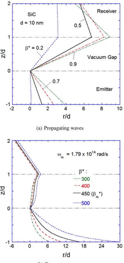
10shows the ESLs for combined TE and TM waves atd= 10nm with different β values. Note that for propagating waves,β∗ = βc/ω <
1 and the shape of ESLs is independent of d in the proximity limit. For evanescent waves, the contribution of TM waves to the near-field radiation is dominant. At the SPhP frequency, ESLs for the sameβd
value are essentially the same. The resonance conditions may be denoted byωmandβm. Whendis very small,ωmdepends little ond, whereas
βmis inversely proportional to das mentioned previously. The value corresponds toβm∗ =βmc/ωm= 450whend= 10nm. For propagating waves, all ESLs are located inside the conical surfaces bounded by the ESL atβ=ω/c(Basu and Zhang,2009a). The ESLs inside the emitter and the vacuum gap are curved much more for evanescent waves than for propagating waves, as it is assumed to be semi-infinite and no backward waves exist. Because the receiver is treated as non-emitting (i.e., at zero absolute temperature), the streamlines in the receiver are straight lines. Figure10(b)suggests that the largest lateral shift occurs inside the emitter and the lateral shift increases withβ. Hence, it is important to take the lateral shift inside the emitter into consideration when determining the minimum area needed for the emitter and receiver to be approximated as infinitely extended plates. In the receiver, the lateral shift can be written asθ(z, ω, β) = tan−1(ε00
/ε0)whenβ∗ 1(orβ ω/c). Hence inside the receiver, ESLs for evanescent waves are parallel as seen in Fig. 10(b). But this is not so for propagating waves when ESLs can intercept each other. The results obtained from this study will facilitate the design of experiments for measuring nanoscale thermal radiation. The method discussed above can be extended to the study of energy flux and streamlines between layered structures and materials with coatings.
4. NEAR-FIELD RADIATIVE ENERGY TRANSFER IN VARIOUS MEDIA
DOI: 10.5098/hmt.v4.1.3001 ISSN: 2151-8629
(a) Propagating waves
(b) Evanescent waves
Fig. 10ESLs for combined TE and TM waves at the SPhP frequency for SiC with d = 10 nm at different β∗ = βc/ω values: (a) propagating waves; (b) evanescent waves (Basuet al.,2011).
addition, near-field radiative energy transport in emerging materials will also be discussed in Sec. 4.4.
4.1. Near-Field Radiative Heat Transfer between Two Spheres
Near-field radiative heat transfer between two spherical nanoparticles has been theoretically predicted by modeling the nanoparticles as fluctuating dipoles (Volokitin and Persson,2001;Dorofeyev,2008;Chapuiset al., 2008b). When there are two spherical nanoparticles whose dielectric constants are ε1 and ε2, the spectral power dissipated in particle 2 by the electromagnetic field induced by particle 1 can be written using the dipolar approximation as
Q1→2(ω) =ε0
ω
2Im(α2)|Einc(x2, ω)| 2
(23)
wherex2is the position of the particle 2 andα2= 4πR3(ε2−1)/(ε2+2) is the polarizability of a sphere of radiusRhaving the relative permittivity of ε2. The electric field incident on the particle 2, Einc(x, ω), is
created by the thermal fluctuating dipole of particle 1 at temperature
T1: Einc(x2, ω) = µ0ω2Ge(x2,x1, ω)·p. Here, Ge(x2,x1, ω) is the electric dyadic Green’s function between two dipoles in vacuum and expressed as (Domingueset al.,2005)
Ge(x2,x1, ω) =
keikd
4π
1
kd+ i
(kd)2 + 1 (kd)3
I+
(uˆruˆr)
3 (kd)3 −
3i
(kd)2 − 1
kd
(24)
whered=|x2−x1|is the distance between the sphere centers,Iis the identity tensor, andˆurˆuris the dyadic notation of unit vectors. Because
of thermal fluctuations, particle 1 has a random electric dipole that yields the correlation function of the dipole:
pm(ω)p
∗
n(ω
0
)
=4ε0
πωIm[α1(ω)]Θ(ω, T1)δmnδ(ω−ω
0
) (25)
Equation (25) is in fact the primitive form of Eq. (1). By combining the above equations, we finally obtain the thermal conductance between two dipoles due to near-field radiative heat transfer that can be expressed as (Domingueset al.,2005):
G12(T) = 3 4π3d6
Z ∞
0
dΘ(ω, T)
dT Im[α1(ω)]Im[α2(ω)]dω (26)
It should be noted that radiative heat transfer between two spheres has the d−6 spatial dependence, which is typical of the dipole-dipole interactions. The thermally fluctuating dipole at one nanoparticle induces electromagnetic field on the other nanoparticle to cause the second dipole to fluctuate. Equation (26) suggests that near-field radiative thermal conductance between two nanoparticles has a resonant behavior when the polarizabilityαhas a resonance, or the dielectric constant approaches −2inα1(2)= 4πR31(2)(ε1(2)−1)/(ε1(2)+ 2). Provided that the surface polariton resonance occurs when the dielectric constant approaches−1 in case the material is interfaced with the vacuum (Raether, 1988), this resonant behavior is not directly related with the surface polariton resonance: instead, is named as the localized surface polariton resonance −grouped oscillations of the charge density confined to nanostructures (Hutter and Fendler,2004). The localized surface polariton resonance appears in the visible range for metals and in the infrared for polar materials.
While the dipole approximation elucidates thed−6
dependence of the near-field radiative heat transfer between two spheres, this depen-dence is valid only when R λT and d R1 +R2, where λT
Frontiers in Heat and Mass Transfer (FHMT), 4, 013001 (2013) DOI: 10.5098/hmt.v4.1.3001
Global Digital Central ISSN: 2151-8629 term. Due to complexities in the formulations, the equations of the
dyadic Green’s function for two spheres are not included here but can be found fromNarayanaswamy and Chen(2008) for a detailed derivation andSasihithlu and Narayanaswamy(2011) for the convergence limit of the vector spherical wave expansion approach.
Domingueset al.(2005) attempted to overcome the limitation of the dipole-approximation by using the molecular dynamics (MD) scheme. After computing all the atomic positions and velocities as function of time using Newton’s second law,P
j
fij =mi¨xi, wheremiandx¨iare
the atomic mass and acceleration andfijis the interatomic force exerted
by atomjon atomi, the power exchange between two nanoparticles (NP1 and NP2) is computed as the net work done by a particle on the ions of the other particle:
Q1↔2=
X
i∈NP1 j∈NP2
fij·vj−
X
i∈NP1 j∈NP2
fji·vi (27)
The interatomic forcefijis derived from the van Beest, Karmer, and van
Santen (BKS) interaction potential (van Beestet al.,1990), in which a Coulomb and a Buckingham potentials are included.
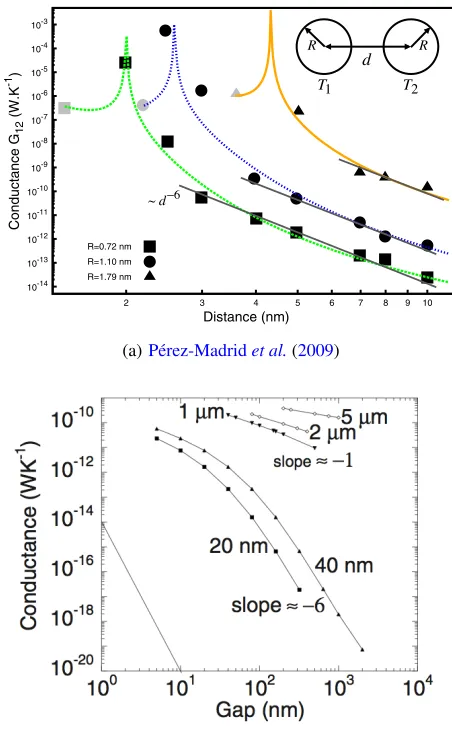
When the interparitlce distance is larger than the radii of spheres, i.e., d ≥ 4R for identical spheres with the radius R, the aforemen-tioned methods (Domingues et al., 2005; Pérez-Madrid et al., 2008; Narayanaswamy and Chen,2008) have a good agreement with the dipole approximation (e.g.,Volokitin and Persson,2001): See Fig.11. However, at smaller interparticle distances, they show different trends. Figure
11(a)shows that the thermal conductance predicted in Refs. (Domingues
et al.,2005) and (Pérez-Madridet al.,2008) has a higher gap dependence thand−6, resulting in four orders of magnitude higher than the dipole approximation in the intermediate distance range, i.e.,2R < d < 4R. This enhanced heat transfer appears to be due to the contribution of multipolar Coulomb interactions (Pérez-Madrid et al., 2008). How-ever, as shown in Fig. 11(b), the thermal conductance calculated by Narayanaswamy and Chen(2008) asymptotically approaches ad−1slope when the interparticle gap distance is much smaller than the particle radius. This slope change is consistent with the result of the proximity approximation or the Derjaguin approximation (Derjaguinet al.,1956). In the Derjaguin approximation, the radiative heat flux between curved surfaces is approximated as the summation of heat fluxes between flat plates that integrate to form the profile of curved surfaces. The consequent thermal conductance is simplified asG12≈πR·d·hr(d, T),
wherehr is the radiative heat transfer coefficient between flat surfaces.
From the previous studies (Mulet et al., 2002;Fu and Zhang, 2006; Basu and Zhang, 2009a), it was found thathr hasd−2 dependence in
the near-field regime. Therefore, the proximity approximation predicts thed−1 dependence in the near-field thermal conductance, which is in contradiction to the> d−6
dependence predicted in (Domingueset al., 2005;Pérez-Madridet al.,2008). While this discrepancy is likely due to the difference in the considered nanoparticle sizes, i.e.,R= 0.72 nm −1.79 nm (Domingueset al.,2005;Pérez-Madridet al.,2008) versus
R ≥ 20nm (Narayanaswamy and Chen,2008), further theoretical and experimental investigations are required to resolve this contradiction in near-field thermal radiation between two spheres.
Another unresolved issue regarding the near-field thermal radiation between spheres is the drastic decrease of thermal conductance when they become in contact. MD simulation (Domingueset al.,2005) predicts that the contact thermal conductance would be 2-3 orders of magnitude lower than the conductance just before contact: see Fig. 11(a). This drastic reduction is still an open question that cannot be explained with the fluctuation-dissipation theorem. At such sub-nanometric distance, nanoparticles cannot be treated as a thermodynamic system at local equilibrium: fluctuation-dissipation theorem is not valid (Pérez-Madrid et al.,2003). The knowledge gap on the thermal conductance change
!j;eq:ðTjÞ ¼expð$"jEnÞ=Pnexpð$"jEnÞ being the
ca-nonical distribution, where"j ¼1=kBTjandEn refers to
the energy levels of the NP, then the current given through Eq. (9) reaches a nonzero stationary value,
Jst¼ @
#%½!1;eq:ðT1Þ $!2;eq:ðT2Þ': (10) The fact that each nanoparticle remains in local equilib-rium with its proper bath corresponds with one among several possible metastable states of the composed system. We find the energy flux by multiplying Eq. (10) through byEnand canonically averaging, yielding
Qð!Þ ¼ @
#%ð!Þ½!ð!; T1Þ $!ð!; T2Þ'; (11) where we have defined the frequency!¼"=@, with " representing the gap between energy levels, !ð!; TÞ ¼
"!Nð!; TÞis the average energy of an harmonic oscillator
andNð!; TÞ ¼1=ðexpð"!=kBTÞ $1Þis the Planck
distri-bution. The heat conductance follows by linearizing Eq. (11) with respect to the temperature difference:
Gð!; T0Þ ¼ kB@ 4#%ð!Þ
! @!=k
BT0
sinhð"!=2kBT0Þ
"2
; (12)
whereT0¼ ðT1þT2Þ=2is the temperature corresponding to the stationary state of the system. It should be noted that these two spheres of the same diameter maintained at different temperatures constitute a model corresponding to more realistic systems such as, for example, a hot tip in contact with a flat substrate, as mentioned above. When d¼2$c=!, a phononlike dispersion relation, Eq. (12) gives us the heat conductance as a function of the distance between the NPs. Here, the effective relaxation time#%ð!Þ
plays the role of an adjustable parameter which in general depends on the frequency according to the fact that for extremely close distances the system adopts a glassy be-havior typical of complex systems.
The intricate slow dynamics which complex systems exhibit is represented by a hierarchy of relaxation times often given by a Kohlrausch-Williams-Watts law [17], #%ðtÞ ¼aexpð$bt"Þ, with 0<")2, also known as stretched exponential and where"is a matching parameter andaandbare constants which depend on the size of the NPs. This is an empirical time law, ubiquitous in disor-dered systems such as glasses which can be related to the distribution of residence times or the response function [16,18]. Therefore, in our case we have tried a time law given by a stretched exponential to make Eq. (12) fit the available numerical simulation data [1]. We have found that an exponent "¼2 for which #%ðtÞ as well as its
Fourier transform#%ð!Þare Gaussians, gives an excellent
fit. This is supported by Fig.1, where we have represented the heat conductance as a function of the distanced be-tween the NPs of different effective radiiR¼D=2. This figure shows a strong enhancement of the heat conductance
whend decreases until around 2D nmdue to multipolar interactions [6]. When both NPs are in contact, a sharp fall occurs which can be interpreted as due to an intricate conglomerate of energy barriers inherent to the amorphous character of these NPs generated by the strong interaction. The behavior shown in Fig.1agrees with what Eq. (12) predicts since in this equation, the two factorskB@=4#%ð!Þ
andfð@!kBT0Þ=sinhð@!=2kBT0Þg2compete. For large dis-tances the dominant factor is the latter factor whereas at contact the former factor becomes the leading term. For large length scales, when#% is almost a constant which corresponds with exponential relaxation, the fluctuation-dissipation theorem is satisfied and we find the system in the fluctuation-dissipation regime. Therefore, the conclu-sions of our theory are clearly well supported by Fig.1 which indicates that the hypothesis of the rough energy landscape is indeed reasonable.
As far as we know the decay in the thermal conductivity at contact is an open question not yet resolved. Here, based on the fact that the crystalline structure of the NPs rapidly disappears when the internanoparticle distance is de-creased [1], the assumption that the resulting amorphous material self-organizes into an irregular distribution of energy barriers is the key to interpreting the origin of this decay. Namely, the classical maximum thermal conduc-tance applies to the fluctuation-dissipation regime before contact in which the system preserves its crystalline struc-ture and optical phonons are mainly excited. However, since it has been observed that both NPs become amor-phouslike particles when they come closer together due to their strong interaction, we have supposed that they behave as glassy materials. In glasses as well as in other disordered materials, it is a known fact that the distribution of modes presents anomalies which result from an excess of
low-10-14 10-13 10-12 10-11 10-10 10-9 10-8 10-7 10-6 10-5 10-4 10-3
2 3 4 5 6 7 8 9 10
Conductance G12 (W.K -1) Distance (nm) R=0.72 nm R=1.10 nm R=1.79 nm
FIG. 1 (color online). Thermal conductanceG12vs distanced
reproducing the molecular dynamics data obtained by Domingueset al.[1]. The grey points represent the conductance when the particles with effective radius R¼0:72, 1.10, and 1.79 nm are in contact. The lines show the analytical result obtained from Eq. (12) by adjusting#%ð!Þto the simulation data.
PRL103,048301 (2009) P H Y S I C A L R E V I E W L E T T E R S 24 JULY 2009week ending
048301-3
~d−6
d
R
T1 T2
R
(a)Pérez-Madridet al.(2009)
(b)Narayanaswamy and Chen(2008)
Fig. 11Thermal conductance between two identical micro/nanospheres computed (a) in the framework of mesoscopic nonequilibirum thermodynamics (Pérez-Madridet al., 2009) and (b) using the vector spherical wave expansion method (Narayanaswamy and Chen,2008). The inset illustrates the sphere-sphere configuration for the identical sphere case. In (a), the marks represent molecular dynamics data obtained by Domingues et al. (2005), where particles with effective radiusR =0.72, 1.10 and 1.79 nm were considered. The grey points represent the conductance when the particles are in contact. When bigger spheres are considered in (b), the gap dependence asymptotically approachesd−1as the gap distance further decreases below the dipole approximation limit. (Figures reprinted with permission of the American Physical Society.)
DOI: 10.5098/hmt.v4.1.3001 ISSN: 2151-8629 4.2. Near-Field Radiative Heat Transfer between a Sphere and a
Half Space
In this part, we discuss near-field thermal radiation between a small spherical particle and a semi-infinite medium, which can be considered as a simplified model of the scanning tunneling microscopy or scanning thermal microscopy (Volokitin and Persson, 2001). Similarly to the previous section, the small particle can be approximated as a dipole of radiusRwith dielectric constantεP(ω)and temperatureTP. The semi-infinite surface is maintained at temperature TBand has the dielectric constantεB(ω). The center of the particle is at a distancedabove the interface. Then, the spectral mean power radiated by the half space and absorbed by the particle can be written as (Muletet al.,2001)
PB→P(ω) = 2ω
4
πc4Im[εB(ω)]Im[αP(ω)]Θ(ω, TB)
X
n,m=x,y,z
Z
B
Gnm(xp,x0, ω)
2
d3x0 (28)
When the fluctuating currents inside the particles radiate into the half space and dissipate, the locally dissipated power per unit volume at a pointxinside the space can be written as
PP→B(x, ω) =
2ω4
πc4Im[εB(ω)]Im[αP(ω)]Θ(ω, TB)
X
n,m=x,y,z
|Gnm(x,xp, ω)|2 (29)
whereαP(ω) = 4πR3[εP(ω)−1]/[εP(ω) + 2]is the polarizability of the dipole andGnm(x,x0, ω)is (n,m) component of the dyadic Green’s
function atxdue to a point source atx0in a system constituted by two semi-infinite media whose dielectric constants are either 1 ifz ≥ 0or
εB(ω)ifz <0. It should be noted that the dipole polarizability needs to be corrected to take into account the interaction between the dipole and the interface whendis comparable toR(Dorofeyev,1998).
WhenPB→P(ω)is calculated for a SiC spherical particle at temper-atureTP = 300K of radiusR= 5 nm at different distances above the SiC surface (Mulet et al., 2001), two peaks are observed at frequency
ω1 ≈ 1.756×10¹⁴ rad/s and ω2 ≈ 1.787×10¹⁴ rad/s, each of which corresponds to the localized surface polariton resonance of the SiC particle (i.e., Re [εP] = −2) and the surface polariton resonance on the SiC surface (i.e.,Re [εB] =−1), respectively. Moreover, near-field radiative heat transfer increases showing the d−3 dependence as
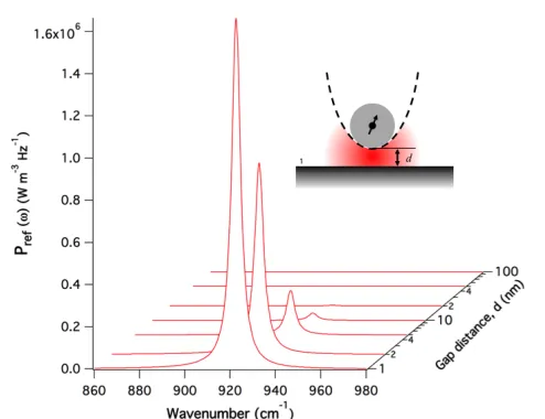
ddecreases, enhanced by several orders of magnitude than the far-field thermal radiation. Another example is shown in Fig. 12, which plots
PP→B(ω)emitted from a SiC particle of radius R= 25 nm heated at
TP= 1000K to a gold surface right below the particle. There is a sharp peak at∼930 cm−1, corresponding toω≈1.756×10¹⁴
rad/s or 10.6µm when the tip is near the surface, suggesting that the heated SiC particle emits a quasi-monochromatic thermal radiation at around 10.6µm in the near-field regime.
It should be noted again that the dipole approximation for a sphere is valid whenR λT andd ≥ 2R. In the other extreme case, i.e.,
dR∼λT, the dipole approximation may not be valid, and instead we
should use the proximity approximation (or Derjaguin approximation). Applying the proximity approximation for the sphere-flat surface case, the near-field thermal conductance has thed−1 dependence, instead of
d−3. This result was experimentally validated as will be discussed in the following section. A further research was conducted to seek the shape dependence of near-field radiative heat transfer when a spheroidal metallic nanoparticle is in proximity to a planar metallic sample (Huth et al.,2010). By changing the aspect ratio of a spheroidal particle from 1/5 (long axis perpendicular to the surface) to 5 (long axis parallel to the surface) while fixing its volume, they predicted that the total radiative heat transfer between a gold spheroid at 100 K and a gold planar surface
Fig. 12Mean spectral power radiated from the SiC particle (of radiusR= 25 nm and held atTP= 1000K.) to the gold surface right below the particle.
at 300 K at the gap width of 100 nm changes from about half to two times of that between sphere and planar surface.
4.3. Near-Field Radiative Heat Transfer in Cylindrical Objects
While various geometries of nanostructures are being developed as potential candidates for efficient heat transfer sources, it is not an easy task to theoretically investigate radiative heat transfer from or between such nanostructures. The thermal radiation of long cylindrical objects whose thickness is in the range of the thermal wavelength is a good example, as it can be very different from the classical blackbody radiation described by Planck’s law (Öhman,1961). Recent experimental studies on thermal radiation of an antenna-like platinum microheater (Ingvarsson et al., 2007;Au et al., 2008), a single SiC whisker antenna (Schuller et al.,2009), thin tungsten wires (Bimonteet al.,2009) and individual carbon nanotubes (Fanet al.,2009;Singeret al.,2011) demonstrated that thermal radiation from sub-wavelength cylindrical emitters has coherent features and thus can be polarized depending on the orientation of the emitters. Polarization effects were also observed from the thermal radiation of carbon nanotube bundles (Liet al.,2003), which could be used to probe the degree of alignment inside the bundle. Some works (Schulleret al.,2009;Singeret al.,2011) further studied the polarized thermal radiation by developing a simple theoretical model based on the Mie theory and comparing with the measurement, revealing that the degree of polarization is affected by the optical conductance along with the geometry of the cylindrical thermal emitter. However, the Mie theory could not correctly deliver the frequency-dependence of the degree of polarization, requiring a more comprehensive theoretical model. The Kadar group at MIT has developed a general formalism to compute the heat radiation of arbitrary objects in terms of their classical scattering properties based on the fluctuation-dissipation theorem (Krüger et al., 2011;Golyket al.,2012). They predicted that the degree of polarization of the emitted radiation depends on the cylinder radius: if the radius is much smaller than the thermal wavelength, the radiation is polarized parallel to the cylindrical axis and becomes perpendicular when the radius is comparable to the thermal wavelength.
![Fig. 2 Dispersion relation of SPP as manifested by an Ag grating [(b) Dispersion relation19]](https://thumb-us.123doks.com/thumbv2/123dok_us/8813741.1779105/5.612.322.566.362.707/fig-dispersion-relation-spp-manifested-grating-dispersion-relation.webp)