Research Journal
Volume 11, Issue 3, September 2017, pages 114–121
DOI: 10.12913/22998624/75968 Research Article
VARIABLE VALVE TIMING SCHEDULING IN A 4-STROKE INTERNAL
COMBUSTION CYLINDER UTILIZING ARTIFICIAL NEURAL NETWORKS
Sepehr Bapiri1, Omid Chaghaneh2, Hossein Ghomashi2
1 Faculty of Mechanical Engineering, Istanbul Technical University, Istanbul, Turkey, e-mail: [email protected] 2 Department of Mechanical Engineering, South Tehran Branch, Islamic Azad University, Tehran, Iran, e-mail:
[email protected], [email protected]
ABSTRACT
The apparently simple structure of a four-stroke internal combustion cylinder belies the complicated problem of optimizing valve operation in response to a change in crankshaft rotation speed. The objective of this study was to determine the cylinder pressure for valve event angles in order to determine the optimal strategy for the tim-ing of valve events when independently-actuated valves are available. In this work, an artificial neural network is applied to create a prediction matrix to anticipate the best variable valve timing approach according to rotation speed.
Keywords: Variable valve timing, cylinder pressure, independent valve operation, artificial neural network.
INTRODUCTION AND PROBLEM
STATEMENT
In a conventional four-stroke engine with or without spark ignition, designers must align the
burn phase with the maximum pressure event,
as demonstrated in a model by S. Kuo [17]. This timing is invariant, but inlet valve lifting at the
first stroke and exhaust valve opening at the last
stroke can only be prevised under optimal
op-eration for a specific crankshaft rotation speed
with traditional camshaft coupling. The problem emerges when the speed changes, as the load or fuel rail pressure conditions then change so that the valves must close or open earlier or later to prevent the fuel gas inlet or emission outlet from interfering with the other strokes.
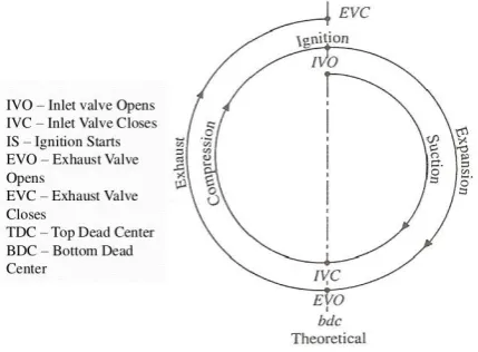
Before defining the problem, the valve events should be explained. Theoretically, suction and exhaust events should occur at the top and bottom
of the piston at dead centre, but in practice, these events occur either earlier or later. Figure 1 shows a common representation of the cylinder events according to crank angle in a timing diagram.
Correct timing is essential to engine effi -ciency. Issues such as valve inertia and path
re-luctance against the flow prevent the timing from
being ideal at a given moment; thus, the practical engine must contain lead-lag events such as inlet valve opening (IVO). These events are set to oc-cur at -10° to 25° for the top dead center (TDC). Inlet valve closing (IVC) occurs at -25° to 50°
around the bottom dead center (BDC) and ex -haust valve opening (EVO) at -30° to 50° at the
BDC. Exhaust valve closing (EVC) occurs at -10° to 15° around the TDC and fluid motion is even
more tightly limited within these spans. This is where the problem occurs.
In an article by Joonsup Han [12], the authors
found that if the exhaust valve opens too late, the
burned gas volume inside the cylinder will in-crease and the pressure will dein-crease. This leads
to loss of work that is needed to push the fluid
out. If this valve opens too early, some of the en-ergy of ignition will leach out. Furthermore, if the
exhaust valve closes too late, some of the waste
may be pulled back in and occupy space,
nega-tively affecting combustion. If the intake valve
opens too early, the expanding emissions create excess pressure which may find its way to the fuel
rail and contaminate the fuel supply. If the input
valve closes too late, the maximum pressure and
temperature conditions suitable for ignition may be lost. The valve motions are often triggered by the camshaft, which rotates at half the crankshaft speed; thus, it is not possible to manipulate events into a more optimal timing when the speed alters.
In order to resolve these issues, a fully-flexi -ble valve actuation system is required to continu-ously vary the valve opening and closing times according to the crank angle. Such a design could maintain the optimum timing at all spins. A num-ber of variable valve timing systems which have already been introduced or are under develop-ment, are mentioned in a paper by Carrie M. Hall [5]. Earlier systems discussed in S. M. Rabia’s pa-per [18] rely only on discrete steps applied to the proportion between the crankshaft and camshaft,
but such a design cannot be completely effective because a shift in one will have an effect on the
other events. For instance, if the IVC lags by 10°,
the IVO, EVC and EVO will also experience a
delay. The current study does not discuss ways of devising variable valve timing (VVT) systems,
but studies the effect of fully-variable VVT on cylinder output to find a way to supervise those events with a trained prediction matrix.
LITERATURE REVIEW
Attempts have been made to devise meth-ods of developing and applying VVT to engine
performance, but most are executed by gather -ing practical data without try-ing to identify the plan and its mathematical models and others are
simply application techniques. One early study by Luria D. [15] concluded that enforcing varia-tions in the IVC could be advantageous. Fontana G. [9] utilized detailed computer simulations of physical traits to show that, in both single- and multi-cylinder engines, late IVC (LIVC) can di-minish the pressure tension caused by manifold pulsations. If some of the new charge is pumped backward, a more uniform residual gas distribu-tion between the cylinders will be achieved. In one article, Tuttle J. [20] reported that LIVC will not increase fuel consumption. This is contrary to the results reported in Wu C’s paper [21] in which LIVC caused a four-cylinder four-stroke engine
to improve full-load engine efficiency by 11%.
Although late EVO (LEVO) decreases the ex
-haust gas pressure and requires work for pumping out, Hara S. [11] found that this could improve
volumetric efficiency if the exhaust gas is fully
pumped out by the piston, because no residual gas will remain inside.
Kang J. Mo [13] equipped a diesel engine with a pneumatic inlet-valve controller which acts using a nonlinear mean value model under wide-gap dynamic conditions, and the results show some improvement. Benson R. S. [1] dem-onstrated that a four-cylinder four-stroke diesel
engine can benefit from LIVC with regard to fuel savings, volumetric efficiency and residual gas
discharge. Similarly, Saunders R. J. [19] showed that an overall VVT approach can improve fuel economy in diesel engines. Fiorenza R. [8] con-cluded that a continuous VVT can increase the
output torque. Caufield S. [6] reported that VVT
can decrease fuel consumption in small
spark-ignition (SI) engines through accurate fluid path
simulations. The VVT issue has been shown to
be of even more benefit for auto-ignition diesel engines by Cao L. [4], who discussed its effect on
gas composition and combination.
The utilization of artificial neural networks
(ANNs) to anticipate the best valve event
con-figurations has been examined by Gölcü M. [10],
Bin Wu [2] and Khaldoun K. [14]. These studies
lack proper modeling and insist on using experi
-mental data to train the ANNs, which is expensive
and may be unreliable.
While a considerable number of studies have addressed VVT, nearly all have concentrated on physical simulations. Mathematical modeling of
makes the task of studying cylinder behavior for the full range of valve events difficult and expensive
to achieve. The current study formulated pressure production inside a cylinder and used optimization techniques to observe and anticipate possible changes due to VVT.
CURRENT WORK
Cylinder Pressure Formulation
Three timing diagrams (inlet valve, outlet valve and piston position) are required to study cylinder events as independent events and to give cylinder pressure and piston operation as outputs. Traditionally,
the camshaft rotates twice per crankshaft cycle, beginning from the zero angle θ0 when the piston is in the fully-folded position and there is virtually no gas remaining inside the cylinder.
The crankshaft rotates at speed ω and causes the piston to move; this speed is assumed to be constant for two rounds. The effect of valve operation is on the gas inlet-outlet through the opened pathway. The pressure difference through a passage between two containers can be formulated as:
(1) where: R is the passage reluctance depending on valve motion.
The cylinder pressure varies according to the relocated fluid mass and piston location; thus, some of the smaller effects could be delayed. The cylinder capacity changes as the piston moves according to:
(2) According to Boyle’s law, if no thermal event has occurred, the volume-pressure product remains constant. Volume as a variable only depends on crankshaft speed while pressure is related to volume, valve events and combustion. Because valve events occur within a short angle span during crankshaft
rotation, the effect of a change in volume on the imported fuel mass can be neglected, and it is assumed
to be dependent only upon the valve event according to:
(3) where: R is a factor which can be determined experimentally, but can also be modelled as a factor of a
sinusoidal function dependent upon the main shaft angle and cylinder pressure.
The inlet fuel mass varies exponentially, but in reverse quantities. The IVC event occurs at θ1 if the
ignition instant corresponds to θ2 and the cylinder pressure between the IVC and ignition depends only
on the volume. At the moment of ignition, the pressure dramatically increases as the volume and ignited
fuel mass increase. Some studies have used a differential equation for the consumption of the fuel mass as reported in an article by Osama H. [16]:
(4)
where: θ is the current angle, θb is the total burn angle, and A and M are constants that depend upon the fuel type.
The produced pressure increases as the ignited fuel mass increases, but decreases as the volume increases.
(5) After combustion, EVO occurs when the system is designed under conditions approaching those
described in Eq. (1). If the exhaust is delayed too long, the pressure difference between the exhaust
chamber and the cylinder may decrease such that much work would be required to pump out the emis-sions. If it occurs too early, some of the work from combustion may be wasted. Some studies suggest that if the IVO event occurs concurrently with the EVO, this could aid emissions, but it is not possible to predict the quantity of fuel injected with such accuracy.
The overview of cylinder events makes it possible to describe the cylinder pressure and volume for
There are two major considerations with
respect to the events. The first is that the valve
events are considered to be independent of crank-shaft rotation; at any given moment, however, the
cylinder pressure can be affected by this parame
-ter. The second is that the piston stroke concurrent with the cylinder pressure can indicate whether or not the piston can yield energy from the pressure. Because the piston motion is necessarily inde-pendent of the valve events, a strategy could be developed to formulate them all. This has seldom been a feature of previous studies. Although valve events are independent, the instant of ignition is always at the TDC.
Model Verification
Before suggesting improvements, the
cur-rent modelling approach must be verified by
comparing the results of simulations with physi-cal sensory measurements and with the results of the mathematical calculations. Application of the equations in a programming environment allowed comparison of the results with those of other studies, such as the thesis of Chedthawut P. [7]. It was concluded that the proposed model is quite accurate for the parameters tested, although in nearly all other research cylinder pressure was introduced as the only practicably measurable
inside the cylinder for either the fuel rail or the exhaust chamber determines whether the cylinder can absorb energy or must be fed work in the suction or exhaust phases; thus, the pressure parameter must be identified and simulated. After resolving the rule describing differential equations with acceptable
precision, the cylinder pressure behaviour can be modelled as:
(6)
where: APcy1 is the fuel mass allocated during the IVO event. It is assumed that the effect of changes in cylinder volume is negligible during the ignition phase because the ignition effect is dominant. This effect is modelled as V(θ) during valve events where PV = fluid energy.
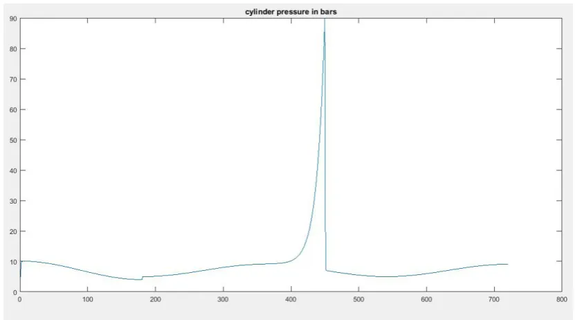
value and was not thought to be predictable. A simulation program should be developed to cover the overlap between valve events by summing
the effects, as is done for the effect of cylinder volume as an external independent variable. The
predicted cylinder pressure under conditions sim-ilar to those in the previously-mentioned thesis is shown in Figure 2.
A cylinder pressure simulation is required in which the ignition-combustion pressure is physi-cally simulated. For this purpose, a model was developed in ANSYS Fluent that is based upon the eddy dissipation model by Bjørn F. [3]. For
most flammable admixtures, ignition proceeds
rapidly and is only controllable by the
manipu-lation of the mixture ratios. Such mixing limits
combustion so that the chemical reaction time is scalable (eddy dissipation) and combustion
oc-curs whenever turbulence ococ-curs in the flow. No
source of ignition is required if the turbulence can
create sufficient temperatures to initiate combus -tion. These ignition events can be simulated with smaller timescales when comprehensively stud-ied using the eddy dissipation method.
In the proposed simulation, the valve events are not summed over the full cylinder cycle. The results show only the combustion-phase pressure where ignition occurs at the TDC. This feature is common to both SI and diesel engines as it is assumed that the spark only occurs at the TDC. The current simu-lation results for pressure at the piston surface are shown in Figure 3. One could safely presume that the application of valve event factors could alter the graph to make it similar to that shown in Figure 2.
Figure 4 shows the graphical results for the final
moment of the cylinder ignition simulation.
Full-range VVT Effects
Using the information obtained thus far makes
it possible to study the effects of the full range of VVTs for combustion efficiency by comparing
the generated pressure and volume with piston motion data. If the pressure increases as the vol-ume increases, kinetic energy is being absorbed from the cylinder event. If the volume decreases as the pressure increases, the energy is being ab-sorbed by the cylinder event. A volume-pressure graph can track the energy events in the cylinder.
The effect of valve timing at different crankshaft
speeds can be studied. In order to avoid depiction of the demographic images of the two parameters for each event and crankshaft speed setup, a
cyl-inder efficiency parameter must be defined as:
Fig. 3. The cylinder pressure at a cycle with only assuming the ignition event and denying the valve events to be effective, obtained from the simulation
based upon the eddy dissipation
Fig. 4. Temperature-Pressure distribution inside a cylinder at the ignition instance
where: the energy is in proportion to the differ -ential sign of the volume and pressure ap-plied to the multiplication of the param-eters themselves.
The efficiency parameters measured under
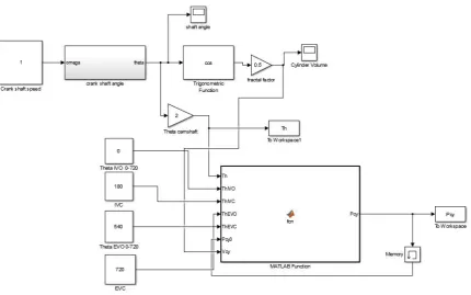
the conditions shown in Figure 2, are depicted in Figure 5. Now that the quality has been en-sured, the following Simulink diagram is pro-posed, and crankshaft rotation speed changes
are applied in Figure 6. The crankshaft speed
angle was also applied in MATLAB Simulink. The output work is calculable as follows with
respect to the force-displacement profile en
-forced for the piston: W = FR.
A common four-stroke four-cylinder engine can operate at crankshaft speeds of up to 50 rounds per second (3,000 rpm), where two cycles
execute a complete cylinder action set. To inves
-tigate the full effects, the input rotation speed can
be varied in the range 1-50 rounds per second, the IVO between 0° and 90°, the IVC between 90°
and 180°, the EVO between 540° and 630° and the EVC between 630° and 720°. The ignition point is considered to be constant at 360° and the
total ignition angle at 540° (power stroke).
RESULTS AND CONCLUSIONS
It is only necessary to vary the valve events at each crankshaft speed and record the cylinder
efficiency for each set. Table 1 shows the best
conditions for a cylinder resulting in the highest
efficiency rate. The variables are changed using
10 crank-angle steps. Such a set of data can be used to determine the required valve event angles
in order to optimize cylinder efficiency with re
-spect to crankshaft speed by calculating the mean values for two columns of the table, repeating the simulation or using a trained prediction al-gorithm like ANN. Further investigations could test an actual internal combustion engine using all necessary instruments.
All other parameters were kept constant. The calculations are performed at full load conditions. It shows a decrease in power with the (EVO) an-gle reduction for all engine running speeds. But it is less sever at lower engine speed (less than 1500 rpm). At low speeds, a late (EVO) reduce
the volumetric efficiency. But in contrast at high
engine speeds, early (EVO) leads to greater
reduc-tion in volumetric efficiency and it causes a limi -tation in the output power. This is due to the less
effective scavenging of the cylinder, as the pres -sure decreases. Power is drawn versus the EVC
angle for different engine speeds between (1000 -
5000 rpm). It shows an increase in power with the (EVC) angle reduction but this increase in power
was small for values of (EVC) less than 25˚ for all engine running speeds considered. This effect is
more recognized at higher engine speeds (2500-5000 rpm). The increase in power may be due to
the reduction of residual gases and backflow of exhaust into the inlet manifold, but a late (EVC)
closing causes the high pressure exhaust gas re
-ducing the amount of inlet mixture incoming
through the inlet manifold. A retarded valve close
angles creates a considerable reverse flow and re
-sults in the reduction of cylinder’s volume effec
-tiveness and internal exhaust gas recirculation.
The presented investigation has provided a suitable modeling approach to simulate cylinder
volume-pressure profiles and thus avoid the ex
-pensive experimental tests suggested in previous
studies. The proposed model anticipates engine behavior and cylinder productivity at variable
speeds and different arrangements of valve event
angles. The results table indicates that as shaft ro-tation speed increases, earlier IVO overlap with
EVC could improve cylinder efficiency, and ear
-lier IVC is needed to improve fuel mass compres-sion inside the cylinder. At the same time, late EVO is desirable to prevent loss of ignition en-ergy. Apparently, as the engine speed increases,
lower efficiency rates are retrievable
These results can be used to establish a VVT lookup table for the designs for which indepen-dent valve actuators are available. It is also
pos-sible to use the data to create and train an artificial neural network matrix to predict the most suitable
valve event angles with respect to engine output speed, utilizing its regression feature. In addition, because the moment of ignition is assumed to be constant at the TDC point, testing will be reliable for both SI and diesel four-stroke engines.
This work has not yet considered parameters such as variable fuel rail pressures and fuel
ad-mixture, insufficient combustion procedures or the effect of the possible remaining exhaust gas
inside the cylinder, because there are almost no comprehensive simulation environments avail-able which could cover all the elements. Further-more, providing such a thorough formulation will
require extensive testing instruments to verify the
model, and other approaches could be assumed to
be as effective.
The contribution of the final strategy in this scheme, refer to engines with one exhaust and
one inlet camshaft each. Engines with more than
one exhaust and one inlet camshaft require a
Hall sender and a valve for camshaft adjustment for each camshaft.
REFERENCES
1. Benson, R.S., Annand, J. D. and Baruah, P.C., A simulation Model Including Intake and Exhaust Systems for a Single Cylinder Four-Stroke Cycle Spark Ignition Engine, Int. J. Mech. Sci, Pergamon Press, 17, 1975, 97-124.
2. Bin Wu, Using artificial neural networks for repre -senting the air flow rate through a 2.4 liter VVT en -gine. SAE Technical Papers. Powertrain and Fluid Systems Conference and Exhibition, Tampa, FL, United States, 25-28 October.
3. Bjørn F. Magnussen, The Eddy Dissipation Con-cept A Bridge Between Science And Technology ECCOMAS Thematic Conference on Computa-tional Combustion, Lisbon, June 21-24, 2005. 4. Cao L., Zhao H., Jiang X. and Kalian N.,
Under-standing the Influence of Valve Timings on Con -trolled Auto-Ignition Combustion in a Four-Stroke Port Fuel Injection Engine. Journal of Automobile Engineering, 6 (219), 2005, 807-823.
5. Carrie M. Hall, Combustion Phasing Model for Control of a Gasoline-Ethanol Fueled SI Engine with Variable Valve Timing, American Control Conference Fairmont Queen Elizabeth, Montréal, Canada June 27-June 29, 2012.
6. Caufield S, Rubenstein B, Martin JK, et al. A com -parison between CFD predictions and measurements at inlet port discharge coefficient and flow character -istics. In: SAE Paper No. 1999-01-3339 in the small engine technology conference and exposition; 1999. 7. Chedthawut Poompipatpong, Effects Of Intake
Valve Timing And Injection Timing In A Natural Gas Dedicated Diesel Engine. Msc Final Thesis, King Mongkut’s Institute Of Technology North Bangkok Academic Year 2007.
8. Fiorenza R, Pirelli M, Torella E, et al. Variable swirl and internal EGR by VVT application on small displacement 2 valve SI engines: an intel-ligent technology combination. In: FISITA 2004 world automotive congress. May 23–27.
9. Fontana G., Galloni E., Variable valve timing for fuel economy improvement in a small spark-igni-tion engine. Elsevier Journal of Applied Energy 86, 2009, 96–105.
10. Gölcü M., Artificial neural-network based mod -eling of variable valve-timing in a spark-ignition engine. Elsevier Journal of Applied Energy, 2 (81), 2005, 187–197.
12. Joonsup Han, Jaehyeon Lee, Hyungmin Kim, Ki-hyung Lee, A Study on the Effect of Valve Tim -ing on the Combustion and Emission Character-istics for a 4-cylinder PCCI Diesel Engine. World Academy of Science, Engineering and Technology International Journal of Mechanical, Aerospace, Industrial, Mechatronic and Manufacturing Engi-neering, 10 (4), 2010.
13. Kang, J.Mo. and Grizzle, J.W. Dynamic control of a SI engine with variable intake valve timing. International Journal of Robust and Nonlinear Control, 5 (13), 2003, 399-420.
14. Khaldoun K. Tahboub, An ANN-GA Framework for Optimal Engine Modeling. Mathematical Prob-lems in Engineering, vol. 2016, Article ID 6180758, 8 pages, 2016. doi:10.1155/2016/6180758.
15. Luria D., Taitel Y., And Stotter, A., The Otto–At-kinson Engine anew Concept in Automotive Econ-omy. SAE paper 820352, 2002.
16. Osama H. M. Ghazal, Modeling the Effect of Vari -able Timing of the Exhaust Valves on SI Engine
Emissions for Greener Vehicles”, SCIRP journal of Energy and Power Engineering, 5, 2013, 181-189. 17. Paulina S. Kuo, Cylinder Pressure in a Spark-Igni-tion Engine: A ComputaSpark-Igni-tional Model”, J. Under-grad. Sci. 3, 1996, 141-145.
18. Rabia S. M., Effect Of Valve Timing And Exhaust Back Pressure On The Performance Of Gasoline Engine, Journal of Engineering Sciences, Assiut University, 3 (38), 2010, 685-696.
19. Saunders, R.J., And Rabia, S.M., Part Load Ef-ficiency in Gasoline Engines, paper presented at Institution of Mechanical Engineers, Combustion Engines Group, 1986.
20. Tuttle JH, Controlling engine load by means of late intake-valve closing, In: SAE paper No. 800794 in the automotive engineering congress and exposi -tion; 2008.