Research Journal
Volume 10, No. 31, Sept. 2016, pages 177–184
DOI: 10.12913/22998624/64063 Research Article
EXPERIMENTAL AND NUMERICAL ANALYSIS OF THE COMPRESSION
THIN-WALLED COMPOSITE PLATE
Katarzyna Falkowicz1, Przemysław Mazurek2, Patryk Różyło1,
Paweł Wysmulski1, Wojciech Smagowski3
1 Faculty of Mechanical Engineering, Department of Machine Design and Mechatronics, Lublin University of Technology, Nadbystrzycka 36, 20-618 Lublin, Poland, e-mail: [email protected], [email protected], [email protected]
2 Faculty of Mechanical Engineering and Aeronautics, Rzeszow University of Technology, Powstańców Warszawy 12, 35-959 Rzeszow, Poland, e-mail: [email protected]
3 Faculty of Mechanical Engineering, Department of Applied Mechanics, Lublin University of Technology, Nadbystrzycka 36, 20-618 Lublin, Poland, e-mail: [email protected]
ABSTRACT
The subject of research is a rectangular plate with a cut-out subjected to regular com-pression. The plate articulately supported on the short side edges, made of a composite
with high strength properties. The study concerned the numerical finite element analy -sis linear and nonlinear stability of the structure and the experimental validation of the results. The instrument used was a numerical program ABAQUS®.
Keywords: numerical analysis, critical force, buckling, postbuckling.
INTRODUCTION
Thin-walled construction, are a very specific group of supporting structures which have very good strength and stiffness indicators in relation to their own weight. These are the decisive fea-tures for the use of thin-walled composite ele-ments as support eleele-ments in the automotive [2], the aerospace [16, 18, 22] or the space industry where there are quite rigorous performance re-quirements regarding the structure work in the complex load conditions. The specificity of thin-walled supporting structures causes that in case of a specific state of the load its elements can be exposed to the possibility of loss of stability within the exploitation load conditions. There-fore, in addition to the requirements of strength with regard to the thin-walled structures there are also relevant requirements regarding stiffness, which help protect the structure from premature destruction as a result of loss of stability of its
elements. Thus, knowledge about the value of critical load at which the structure loses stabil-ity is one of the very important issues. In some cases, the critical load can lead to the destruction of structure [1, 26], then they are treated as a limit load. The exemplary papers dealing with local buckling of thin-walled structures are those writ-ten by Davis and Hancock [4, 27], Graves-Smith [5] and Kumar [19]. The buckling of open section beams was the subject of the papers [3, 8]. Most of the thin-walled structures are characterized by the ability to work after the loss of stability (this concerns mainly the elastic buckling of local character) in the so-called. the elastic post-critical condition. In such cases, definition of limit load structure elements requires analysis also able post-critical until the destruction of the structure. In the worldwide literature, studies into nonlinear problems of stability of thin-walled structures can be found easily, for example Koiter [13], Debski [5, 7], Kopecki [15, 17], Mania [21] and [9].
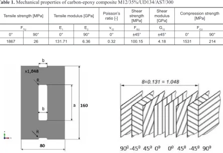
The subject of research was the thin-walled plate with a central rectangular cut-out made of carbon-epoxy composite, the material data pre-sented in Table 1.
The structure of the laminate was composed of 8 layers of the same thickness of 0.131 mm in a symmetric system of layers with respect to the median plane of the composite. Research were conducted on a composite plate at con-figuration of the layers (90 / -45 / 45 / 0) s. Dia -gram geometric of the plate with cut-out shows Figure 1. The analyzed plate had a symmetrical cut-out in the middle. The dimensions of the cut-out are following height: a = 100 mm and width: b = 30 mm.
cal simulation using the finite element method. Conducted experimental studies on the pro-duced thin-walled composite plate allowed the observation of the actual behavior of the structure in a critical and post-critical state, while enabling the identification of the form of buckling and to determine the value of the crit-ical load. Conducted simultaneously numercrit-ical simulations were carried out in order to elabo-ration adequate models MES verified experi-mentally, allowing modeling of problems of buckling of composite thin-walled structures, in a faithful way of imitating the behavior of the real structure.
Table 1. Mechanical properties of carbon-epoxy composite M12/35%/UD134/AS7/300
Tensile strength [MPa] Tensile modulus [GPa] Poisson’s ratio [-] strength Shear
[MPa]
Shear modulus
[GPa]
Compression strength [MPa]
FTU E1 E2 ν12 FSU G12 FCU
0° 90° 0° 90° 0° ±45° ±45° 0° 90°
1867 26 131.71 6.36 0.32 100.15 4.18 1531 214
EXPERIMENTAL RESEARCH
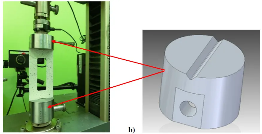
Experimental studies of axial compression of the composite panel was conducted on a universal testing machine, Zwick / Roell Z050 at a constant crosshead displacement rate of 2 mm/min. In or -der to ensure conditions of an articulated support of end edges of plates, designed and manufac-tured special handles for axial compression of the sample. A general view of construction of mount-ing plate on the bench along with the ideological diagram of the handle shown in Figure 2.
In experimental study of buckling of thin-walled structures very important detailed regis-tration of the relevant parameters of the test. In order to adequately describe the critical and post-critical state of structures, it is necessary to reg-ister not only the load, but also displacement at selected points of structure. In the context of the carried out of studies to measure the deflection of plate the ARAMIS system is used. During the measurements were recorded: the duration of the measurement, the compression force of sample, crosshead displacement and deflection of sample. As a result were obtained measurements, on the basis of which characteristics of the disc were de-termined, to assess the critical state.
Occurring in the course of experimental re-search of all kinds of imperfections caused by various independent factors make it difficult to precisely determine the value of the critical load. In such cases, used the methods which allow to
determine the local critical load based on mea-surements obtained in experimental studies. In the present study to assess the value of the critical load were used methods P-w2 and P-w3 [28]. The
applied techniques are associated with the need to perform calculations of approximation, which are allow to fit the function describing analyzed phenomenon, to the received experimentally of test results.
NUMERICAL ANALYSIS
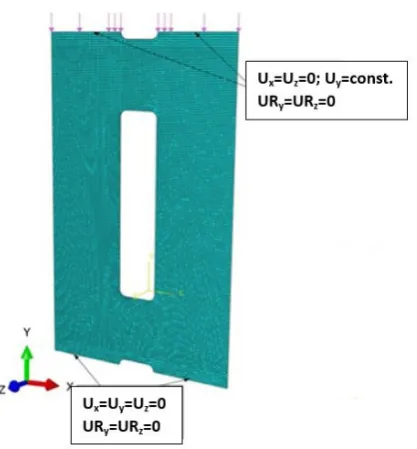
Numerical calculations were carried out in two stages. The first stage were a critical anal -ysis of the structure by using a linear stability analysis „buckling analysis”, allowing the des-ignation of critical compression load of the plate and the corresponding forms of buckling. The second stage of the calculations were the so-lution of the problem of nonlinear stability, in which calculations were carried out on the mod-el with geometric imperfection corresponding to flexural-torsional form of buckling of struc -ture. The work tool which was used in research calculations is a numerical program ABAQUS. In the process of discretization of the analyzed element applied coating finite elements of type SHELL which having six degrees of freedom at each node. The type of finite element which was used to build the model of discrete constituted the four-nodal shell elements with reduced in-Fig. 2. Experimental research: a) general view of the test stand with mounted sample,
tegration with the designation of S4R. In order to modeling the structure of the laminate was used for modeling technique known as Layup-Ply, throughout mapped of the configuration of the layers of the composite. The properties of the composite material were described by de-fining an orthotropic model of material in a flat state of stress. The mechanical properties of the material were adopted in accordance with Table 1. The boundary conditions correspond to the implementation of an articulated support of the composite panel by the task of zero level of dis-placement nodes situated on the upper and lower edge of the plate on the directions
perpendicu-RESULTS AND DISCUSSION
The carried out of experimental research of compressed composite plate with cut-out have provided the information for an assessment the state of deformation of the real structure as a function of external load. The obtained research results allow to make a qualitative and a quanti-tative analysis of the critical and before critical state based on the registered parameters of the sample. The identification of the critical state of the tested element was carried out on the basis of the obtained form of buckling which is the first form of loss of stability and the corresponding its value of the critical load. The designated experi-mentally critical value was the basis for verifica -tion of the results of FEM numerical calcula-tions. The recived the lowest form of buckling of tested composites’ plate has shown in Figure 4.
The qualitative analysis of the results con-firms the compatibility designated by numerical Fig. 3. Discrete model of plate
Fig. 4. The lowest form of plate buckling about the [90/-45/45/0]s layout:
calculations forms of buckling of thin-walled plate with the form of deformation obtained in experimental researches (Fig. 4).
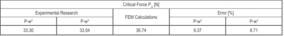
The quantitative analysis of the results al-lows to specify the value of the critical load cor-responding to the obtained the lowest form of loss of stability of the analyzed composite plate. On the basis of the carried out in experimental re-search a deformation measurements as a function of external load were determined average values of the critical force for the analyzed plate with using P-w2 (Fig. 5) and P-W3 (Fig. 6) methods,
which then were compared with the results of FEM numerical calculations (Table 2).
The presented in Table 2 results show a quali-tative and a quantiquali-tative coincidence of critical load values of numerical calculations with ex-perimental results. The designated the value of the critical force by these methods was fraught with error not exceeding 10%, which in the case of thin-walled structures stability analysis indi-cates a high consistency of results. The received the lowest flexural form of buckling does not en -sure the stable plate work as a elastic element. Fig. 5. Example of the result obtained with P-w2 method
Fig. 6. Example of the result obtained with P-w3 method
Table 2. The average values of critical force - a summary of results
Critical Force Pcr [N] Experimental Research
FEM Calculations Error [%]
P-w2 P-w3 P-w2 P-w3
The small increases of load can result in this case to fast destruction of the structure. For this rea-son, in order to ensure the stable plate work in the postcritical range, capable to carrying of higher values of load, it need to force its work by higher flexural-torsional form of buckling. For this pur -pose, in the experimental research applied the extortion of higher form of buckling by the intro-duction of the deflection using a steel rod placed in the mid-plate height (Fig. 7).
In the second stage of the calculation, consti-tuting the solution of the nonlinear stability issue, plate work in postcritical state with forced higher,
flexural-torsional form of plate buckling was ana -lyzed (Fig. 8).
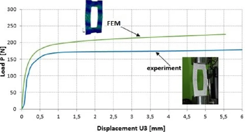
During the structures’ loading in the postcriti-cal range, the same parameters of sample as in the critical range were registered. Postcritical equilib-rium paths in the form of force-deflection graphs, allowing define the characteristic of tested plate in the postcritical range were determined. Post-critical equilibrium paths obtained by numerical method (FEM) in the graph with measurements of experimental research are presented (Fig. 9).
As can be seen, the postcritical equilibrium path which was obtained by experiment, shows Fig. 7. The higher flexural-torsional form of plate buckling about the [90/-45/45/0]s layout:
a) experimental research, b) numerical analysis
Fig. 8. The higher (stable) flexural-torsional form of plate buckling about the [90/-45/45/0]s layout:
less stiffness than the results of numerical calcula -tions. However, the maximum differences do not exceed 27%. This fact results from the higher nu -merical model’ stiffness for which are preserved the ideal conditions of analysis, which is consis-tent with the results of similar studies published in the literature.
CONCLUSIONS
Presented at work results of FEM numerical calculations have been successfully verified by experimental results. The researches on the real structures have allowed to designation of the value of the critical load with the use of methods based on the results of experimental measure-ments. The obtained results of research corre-spond with the results of numerical calculations, which is expressed in satisfactory the compat-ibility of critical load, the difference does not exceed 10%.
The postcritical equilibrium paths, for the real structure and for the numerical model, re-tain the staid character, confirming the validity of the adopted in the numerical calculation of plate model, allowing for the description of the non-linear stability issue. The resulting in the case of the real construction the stable form of work, cor-responding to the higher, flexural-torsional form of buckling, indicates on the possibility to use a thin-walled plate elements with a cut-out for use as the elastic elements.
In carried out studies recived a qualitative compatibility of the lowest form of buckling and the deformation form of the structure in the post-critical range, corresponding to the forced work with a higher, flexural-torsional form. Simultane -ously, the satisfactory a quantitative of compli-ance of the numerical analysis results with the experimental results, confirm the adequacy of the developed numerical model, which in this case maps the behavior of real construction.
REFERENCES
1. Banat D., Mania R.J., Comparison of failure crite-ria application for FML column buckling strength analysis. Composite Structures, 140, 2016, 806-815. 2. Bambach M.R., Fibre composite strengthening of
thin-walled steel vehicle crush tubes for frontal col-lision energy absorption. Thin-Walled Structures, 66, 2013, 15–22.
3. Czapski P., Kubiak T., Influence of Fibre Arrange -ment on the Buckling Load of Composite Plates . Analytical Solution Fibres and Textiles in Eastern Europe, 113 (5), 2015, 92-98.
4. Davids J., Hancock G.J., Compression tests of long welded I-section columns. J Struct Eng, 112 (10), 1986, 2281–2297.
5. Debski H., Eksperimental investigation of post-buckiling behavior of composite column with top-hat cross-section. Maitenence and Reliability, 15 (2), 2013, 106-110.
6. Debski H., Koszalka G., Ferdynus M., Application of FEM in the analysis of the structure of a trailer
ating in the geometrically nonlinear range. Mainte-nance and Reliability, 17 (12), 2015, 222-235. 10. Fedorko G., Molnár V., Živčák J., Dovica M.,
Husáková N., Failure analysis of textile rubber conveyor belt damaged by dynamic wear. Eng. Fail. Anal., 28, 2013, 103–114.
11. Ferdynus M., An energy absorber in the form of a thin-walled column with square cross-section and dimples. Maintenance and Reliability, 15 (3), 2013, 253-258.
12. Graves-Smith T.R., The local buckling of box gird-ers under bending stresses. Int J Mech Sci. 11, 1969, 603–612.
13. Koiter W.T. Elastic stability and post-buckling be-havior. In Proceedings of the Symposium on Non-linear Problems. Wisconsin: Univ. of Wisconsin Press, 1963, 257-275.
14. Kopecki T., Numerical-experimental analysis of the post-buckling state of a segment multi-member thin-walled structure subjected to torsion. Journal of Theoretical and Applied Mechanics, 49 (1), 2011, 227-242.
15. Kopecki T., Numerical and experimental analysis of post-critical deformation states in a tensioned plate weakned by a crack. Journal of Theoretical and Applied Mechanics, 48 (1), 2010, 45-70. 16. Kopecki T., Bakunowicz J., Lis T., Post-critical
de-formation states of composite thin-walled aircraft load-bearing structures. Journal of Theoretical and Applied Mechacnics, 54 (1), 2016, 195-204. 17. Kopecki T., Mazurek P., Determination of stress
distribution patterns in post-critical deformation states of thin-walled skins subjected to operat-ing loads. Maitenence and Reliability, 16 (4), 2014, 608-615.
21. Mania R.J., Kolakowski Z., Bienias J., Jakubczak
P., Majerski K.: Comparative study of FML profiles
buckling and postbuckling behaviour under axial loading. Composite Structures, 134, 2015, 216-225. 22. Orifici A.C., Thomson R.S., Degenhardt R., Kling
A., Rohwer K., Bayandor J., Degradation
investiga-tion in a postbuckling composite stiffened fuselage
panel. Composite Structures, 82, 2008, 217–224. 23. Paszkiewicz M., Kubiak T., Selected problems
concerning determination of the buckling load of channel section beams and columns. Thin-Walled Structures, 93, 2015, 112-121.
24. Różyło P.: Optimization of I-section profile de
-sign by the finite element method. Advances in
Science and Technology Research Journal, 10 (29), 2016, 52-56.
25. Rudawska A., Debski H., Experimental and nu-merical analysis of adhesively bonded aluminium alloy sheets joints. Maitenence and Reliability, 1, 2011, 4-10.
26. Teter A., Debski H., Samborski S., On buckling col-lapse and failure analysis of thin-walled composite lipped-channel columns subjected to uniaxial com-pression. Thin-Walled Structures, 85, 2014, 324-331. 27. Wysmulski P., Dębski H., Różyło P., Falkowicz K., A
study of stability and post-critical behaviour of
thin-walled composite profiles under compression, Main -tenance and Reliability, 18 (4), 2016, 632-637 28. Zaraś J., Królak M., Kotełko M.: Metody
doświad-czalne wyznaczania obciążeń krytycznych i analizy zachowania się elementów konstrukcji
w stanie zakrytycznym. X Krajowa Konferencja
Wytrzymałości Materiałów i Badania Materiałów,
![Fig. 7. The higher flexural-torsional form of plate buckling about the [90/-45/45/0]s layout: a) experimental research, b) numerical analysis](https://thumb-us.123doks.com/thumbv2/123dok_us/8808532.1775926/6.595.83.517.74.275/higher-flexural-torsional-buckling-experimental-research-numerical-analysis.webp)