R E S E A R C H
Open Access
Geometric correction method for 3d in-line X-ray
phase contrast image reconstruction
Geming Wu, Mingshu Wu, Linan Dong and Shuqian Luo
** Correspondence: [email protected] School of Biomedical Engineering, Capital Medical University, Beijing, China
Abstract
Background:Mechanical system with imperfect or misalignment of X-ray phase contrast imaging (XPCI) components causes projection data misplaced, and thus result in the reconstructed slice images of computed tomography (CT) blurred or with edge artifacts. So the features of biological microstructures to be investigated are destroyed unexpectedly, and the spatial resolution of XPCI image is decreased. It makes data correction an essential pre-processing step for CT reconstruction of XPCI.
Methods:To remove unexpected blurs and edge artifacts, a mathematics model for in-line XPCI is built by considering primary geometric parameters which include a rotation angle and a shift variant in this paper. Optimal geometric parameters are achieved by finding the solution of a maximization problem. And an iterative approach is employed to solve the maximization problem by using a two-step scheme which includes performing a composite geometric transformation and then following a linear regression process. After applying the geometric transformation with optimal
parameters to projection data, standard filtered back-projection algorithm is used to reconstruct CT slice images.
Results:Numerical experiments were carried out on both synthetic and real in-line XPCI datasets. Experimental results demonstrate that the proposed method improves CT image quality by removing both blurring and edge artifacts at the same time compared to existing correction methods.
Conclusions:The method proposed in this paper provides an effective projection data correction scheme and significantly improves the image quality by removing both blurring and edge artifacts at the same time for in-line XPCI. It is easy to implement and can also be extended to other XPCI techniques.
Keywords:Projection data correction, Tomography reconstruction, In-line X-ray phase contrast imaging
Background
In recent years, X-ray phase contrast imaging (XPCI) has attracted much attention in many areas, such as bio-medical imaging [1], material science [2] and paleontology [3]. Different from conventional absorption-based X-ray imaging, XPCI uses the informa-tion of wave front changes while X-ray radiainforma-tion passes through a sample. It produces refraction-sensitive images and reveals the internal anatomy of soft tissues with diffe-rences in the refractive indices, which can be described in the complex form as follows
n¼1 −δþiβ ð1Þ
whereδis the decrement of the real part of the refractive index, andβpresents the ab-sorption index of local attenuation. It is proved that δis three orders of magnitude lar-ger than β within the diagnostic X-ray range for human tissue [4]. Thus XPCI can greatly enhance the contrast for soft tissues in biological sample with high spatial and temporal resolutions than conventional absorption-based X-ray imaging technique.
provides a fast and reliable image pre-processing scheme for CT reconstruction in in-line XPCI.
The rest parts of this article are organized as follows: Methods section describes the projection data misplacement problem for CT reconstruction in in-line XPCI and its mathematical model with primary geometric parameters at first, and then in-troduces the proposed method in details. Results section shows numerical experi-mental results from synthetic and real datasets which are pre-processed by the proposed method, and followed by the study conclusion in Consclusions section.
Methods
Projection data correction in in-line XPCI
XPCI uses a spatially coherent beam and an X-ray sensitive detector to acquire pro-jection images from a sample. To obtain 3D structural information of the sample, a rotary stage with high precision is used to put the sample on and a series of projec-tions collected while titling the sample around a rotation axis with respect to the base of stage. In-line XPCI [17] is a propagation-based phase contrast imaging tech-nique and the most simple and straight-forward method to achieve X-ray phase con-trast images. A synchrotron X-ray source, the sample and an X-ray sensitive detector are arranged in line as in conventional radiography but the detector is placed behind the sample in a certain distance. Figure 1 shows the schematic set-up of in-line XPCI.
While reconstructing slice images from acquired projections in in-line XPCI, the center line of any projection is considered to be identical to the rotation axis by de-fault. Following this assumption, reconstruction algorithms, such as FBP, can be employed to build slice images correctly. However, it is usually very hard and time-consuming to align the components of imaging system with micrometer precision. If no data pre-processing step is adapted, the final reconstructed slice images will be blurred and with edge artifacts.
Suppose that Y is along the center line of CCD projection and Z is along the X-ray beam direction. Considering CCD detector and X-ray beam source are fixed during the whole imaging process, we use a model with four geometric parameters to de-scribe the space relationship between the center line of projection and the rotation axis at tilt angle αas illustrated in Figure 2. Here θ is the in-plane flip angle which specifies the slope of the rotation axis related to Y, and (δx,δy,δz) are offsets along X, Y and Z directions respectively.δyandδzare caused by the movement biases of ro-tary stage, andθandδxare mainly due to the misalignment of CCD detector and ro-tary stage. The movement biases of roro-tary stage are controlled by the precision of mechanical design, and thusδyandδzare usually small and can be ignored. Soθand
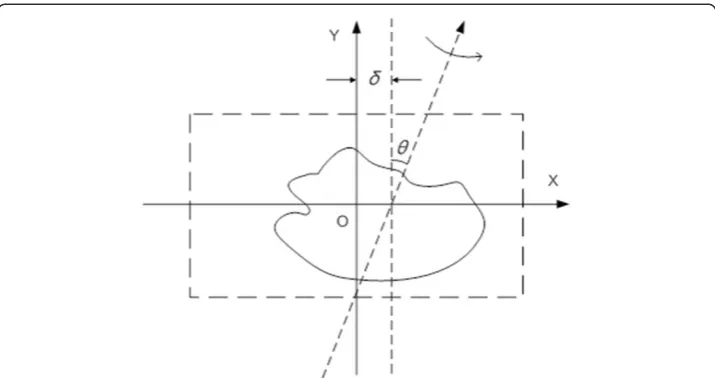
δxare two main factors to be considered and the model is simplified as illustrated in Figure 3. Thereδxis denoted asδ. The existence of two misalignment parameters re-sults in geometric transforms of the projection images. The parameterθis related to the rotation transform of projection images while δto translational transform along X. So the misalignment problem can be solved by applying inverse geometric trans-form to the projection images if we know the values of these geometric parameters.
Translational transform with δ= 2 pixels and rotation transform with θ= 5° are applied to projections respectively. Compared to the result without geometric form, translational transform makes the slice image blurred while rotational trans-form introduces obviously edge artifacts.
Two-step iterative correction method
In-line XPCI has no limitation on the range of tilt angle. Usually two projections with special tilt angle of 0 and 180 degree are included while collecting projections in in-line XPCI. Denote P0 and Pπ the two projections with special tilt angles
re-spectively. According to the physical principle of in-line XPCI,Pπis the reflection of P0 by taking the rotation axis as the mirror line. So Pπ should be identical to the
image which is achieved by applying the following composite geometric transfor-mation toP0in homogeneous coordinates
Figure 2Parameters in geometric model.θdenotes the in-plane flip angle and (δx,δy,δz) are offsets
along X, Y and Z directions respectively.
½
x′ y′ 1¼ 10 01 δ0 0 0 1
2 4
3
5 cossinθθ −cossinθθ 00
0 0 1
2 4
3
5 −01 01 00 0 0 1
2 4
3
5 −cossinθθ cossinθθ 00
0 0 1
2 4
3
5 10 01 −0δ 0 0 1
2 4
3 5 xy
1
2 4
3 5
¼ sin 2 θ−
cos2θ −2 sinθcosθ 2δcos2θ −2 sinθcosθ cos2θ−sin2 θ 2δsinθcosθ
0 0 1
2 4
3 5 xy
1
2 4
3 5
where (x,y) is a point in P0and (x′,y′) is its corresponding position in Pπ. If the rota-tion angleθis small enough, then (x′,y′) is approximated by
x′≈ −xþ2ðδ−θyÞ y′≈yþ2 ðδ −xÞθ
ð2Þ
Thus we obtain
P0ðx;yÞ ¼Pπð2ðδ −θyÞ−x;yþ2ðδ −xÞθÞ ð3Þ The above equation shows that the optimal geometric parameters can be achieved by solving the following minimization problem whenP0andPπare available
Figure 3Geometric parameters in simplified model.θdenotes the in-plane flip angle andδis the offset from rotation axis to the center of projection image along X. Dashed box presents the projection window.
θ;δ
ð Þ ¼ arg min
θ;δ ∬ðP0ðx;yÞ−Pπð2ðδ −θyÞ−x;yþ2ðδ −xÞθÞÞ 2
dxdy ð4Þ
Rewrite Eq. (4) by discarding the constant terms as follows
θ;δ
ð Þ ¼ arg max
θ;δ ∬ðP0ðx;yÞPπð2ðδ −θyÞ−x;yþ2ðδ−xÞθÞÞdxdy ð5Þ To find the solution of the above optimization problem, we employ an iterative scheme. At thekth iteration, the basic step is given by the following iteration
~
θk;~δk
¼ arg max
θ;δ ∫ P0ðx;yÞPπ 2ðδ −θyÞ−x;yþ2 δ~k−1 −x
~
θk‐1
dxdy ð6Þ
The optimizer of Eq. (6) is achieved by using a two-step method which includes per-forming a composite geometric transformationTk−1and then following a linear regres-sion process.
In thekth step,Tk−1is applied toPπto rotate it with the angle −2θk−1and then
re-flect it. HereTk−1is defined as follows
Tk−1¼ 1 0
~
δk−1
0 1 0
0 0 1
2 4
3
5 −01 01 00
0 0 1
2 4
3
5 −cos2sin2θ~θ~kk−−11 cos2sin2θ~θ~kk−−11 00
0 0 1
2 4
3
5 10 01 −~δ0k−1
0 0 1
2 4
3 5
¼ −
cos2θ~k−1 sin2θ~k−1 δ~k−1 1þ cos2~θk−1
sin2~θk−1 cos2θ~k−1 −2~δk−1sin2~θk−1
0 0 1
2 6 4 3 7 5 Pk
π is obtained by applyingTk−1toPπ. It can be proved that we have
Pkπðx;yÞ ¼Pπð2ðδ −θyÞ−x;yþ2ðδ−xÞθÞ ð7Þ Then we seek to find the solution of the following optimization problem
~
θk;~δk
¼ arg max
θ;δ ∬ P0ðx;yÞP
k
π 2 δ− ~δk−1
− θ− ~θk−1
y
þx;y
dxdy ð8Þ
Considering the cross-correlation ofP0andPkπ along X
P0 ⋆Pkπ
t
ð Þ ¼
∫
P0ðx;yÞPkπðtþx;yÞdx; ð9ÞEq. (8) can be rewritten as follows
~
θk;~δk
¼ arg max
θ;δ
∫
P0 ⋆Pk
π
2 δ−~δk−1
− θ −~θk−1
y
dy ð10Þ
The above equation shows that the optimizer of Eq. (8) can be achieved by comput-ing the cross-correlations of P0 and Pkπ row by row, and fitting the positions tm(y), which are corresponding to the maximum of correlation coefficients, with the following linear model
tmð Þ ¼y 2 δ −δ~k−1
−2 θ −θ~k−1
y ð11Þ
Results
To evaluate the proposed method, we carried out experiments on both synthetic and real in-line XPCI data. MC-based sinogram correction scheme and the proposed method have been implemented using MATLAB (The MathWorks, Inc., Natick, MA, USA). Inverse Radon transform with Ram-Lak filter was taken as CT recons-truction algorithm applied to corrected data. Data processing for this paper was car-ried out on a Dell workstation system with a 2.4GHz Intel Core i5 processor and 8GB memory.
Simulation on synthetic data
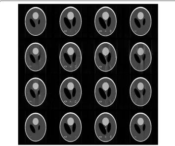
For the synthetic case, we used projections of modified 3D Shepp-Long (S-L) phan-tom in Figure 4 of size 256×256×256 as a test dataset. These projections were ob-tained by using Radon transform after applying geometric transformation with specified parameters to the 3D S-L phantom. 2 pixels shift along axis X was applied to the rotation axis while flip angle was set to−5 degree. Tilt angle ranged from 0° to 180° and 181 projections were built in the simulation with one projection per degree. Figure 5 shows the results of 4 middle CT slices reconstructed without correction (NC), with MC-based sinogram correction (MC), and with proposed geometric cor-rection method(GC) respectively. By comparing these slice images, we confirm that MC-based sinogram correction scheme reduce the blur effect but cannot remove
edge artifacts, and the proposed geometric correction method significantly removes both the blur and edge artifacts at the same time.
For quantitative comparison, we took CT slice images reconstructed from projec-tions without geometric transformation as references, and employed mean Structural SIMilarity (SSIM) index [19] and Mutual Information(MI) [20] to assess the image quality of above results by measuring the similarity between them and the corre-sponding references. For an image X with respect to its referenceY, SSIM index is defined as follows
SSIM xð ;yÞ ¼
2μxμyþC1
2σxyþC2
μ2
xþμ2yþC1
σ2
xþσ2y þC2
ð12Þ
where x and y refer to a local window in the imageX and Yrespectively, μx (μy) is the mean whileσx (σy) is the standard deviation over the windowx(y),σxyis the co-variance betweenxandy,C1andC2are two small positive constants. And the mean
of SSIM index (mSSIM) is the average over all local windows. Mutual information is defined as
MI Xð ;YÞ ¼H Xð Þ þH Yð Þ−H Xð ;YÞ ð13Þ
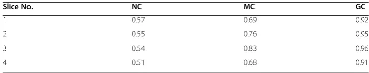
whereH(X) and H(Y) are the Shannon entropy of the image Xand the referenceY re-spectively, andH(X,Y) is the joint Shannon entropy of the imageXand its referenceY. We calculated mSSIM and MI values for the above slice images and listed the results in Tables 1 and 2 separately. Comparing the results, we can conclude that CT slice im-ages reconstructed from projections pre-processed by the proposed method achieve much higher quality than popular MC-based scheme.
In-line XPCI data correction experiment
Real in-line XPCI data was acquired from a mouse lung at X-ray imaging and bio-medical application beamline (BL13W1) of Shanghai Synchrotron Radiation Facility (SSRF). The experiment was approved by the Animal Experiments and Experimental Animal Welfare Committee of Capital Medical University (Beijing, China) and the approval ID is AEEI-2014-049. To prevent from deformation during imaging ap-proach, the mouse lung was fixed in 10% formalin solution, and dried in advance. And then it was put into a small tube, which was rolled by using Kapton film (Dupont, DE, USA), and placed on the rotary stage as illustrated in Figure 1. A Si (111) double-crystal was used to monochromatize the synchrotron ray beam. X-rays with photon energy of 18 keV were chosen to provide both good phase and ab-sorption contrast from the mouse lung. An X-ray sensitive CCD detector with high spatial resolution of 9μm was placed 1.2 m away from the rotary stage along X-ray
Table 1 Comparisons of reconstruction accuracies with mSSIM
Slice No. NC MC GC
1 0.57 0.69 0.92
2 0.55 0.76 0.95
3 0.54 0.83 0.96
downstream to record projection images. During the CT data acquisition, the mouse lung was tilted around rotation axis of the stage from 0° to 180°, and 1296 projec-tions were collected totally with exposure time of 80 milliseconds for each one. The rotary stage was coarse adjusted before the imaging process. To improve the compu-tation accuracy, a simple background subtraction approach was employed before correction schemes were taken by deducting mean value of background region from projection images.
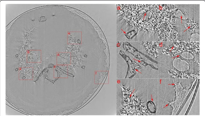
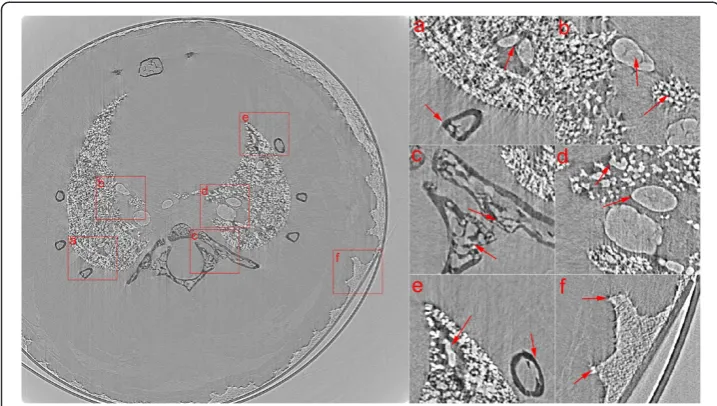
Figure 6 shows one of CT slices reconstructed by FBP with MC-based sinogram correction method while Figure 7 is with the proposed geometric correction method. Six regions of interest (ROIs) are magnified to better visualize the interior details for comparison. Due to the benefits of correcting misplaced projection pixels by using the proposed method, slice images are reconstructed with much less edge artifacts and blurs. Compared to the slice image in Figure 6, more detailed structural features of alveoli, ribs and bronchus of mouse lung are better displayed in Figure 7. The sup-porting walls of two adjacent bronchi can be clearly identified as shown in ROI (a). Alveolar and bronchial walls are closed naturally and with less edge artifacts as dis-played in ROIs (b), (d) and (e). Structures of ribs are more sharp and without blurred as shown in ROIs (a), (c) and (e). And sharp and detailed image of soft tissue can be observed in ROI (f ).
Table 2 Comparisons of reconstruction accuracies with MI
Slice No. NC MC GC
1 1.52 1.60 2.15
2 1.63 1.83 2.60
3 1.62 1.99 2.73
4 1.50 1.64 2.18
Conclusions
CT reconstruction of X-ray Phase Contrast Imaging enables to investigate internal microstructure of biological samples with high resolution. Mechanical imperfect or misalignment problem makes the reconstructed slice images blurred and with edge artifacts, and thus destroy the features of microstructures and reduce the spatial resolution of line XPCI. To restore the images from collected projections by in-line XPCI, a fast geometric correction method is proposed to determine the geomet-ric transform parameters properly. From the results of numegeomet-rical experiments on synthetic and real datasets, we have the conclusion that the proposed method can significantly improve the image quality by removing both blurring and edge artifacts at the same time. Geometric correction method utilizes the symmetry of projections, and thus provides a simple and fast scheme to correct misplaced projection data.
Competing interests
The authors declare that they have no competing interests.
Authors’contributions
The work presented here was carried out in collaboration between all authors. WGM and LSQ defined the research theme, and also designed the methods and experiments. WMS and DLN carried out the laboratory experiments, and WGM analyzed the data, interpreted the results and wrote the paper. All authors read and approved the final manuscript.
Acknowledgements
The authors acknowledge the staffs from beamline BL13W1 of Shanghai Synchrotron Radiation Facility (SSRF) for their kindly support for the experiments. This study was supported by the National Natural Science Foundation of China, Grant No. 61227802, 60532090 and 30770593, and by the 7th Framework Programme of the European Community, Grant Agreement Number PIRSES-GA-2009-269124.
Received: 27 May 2014 Accepted: 14 July 2014 Published: 29 July 2014
References
1. Bravin A, Coan P, Sourtti P:X-ray phase-contrast imaging: from pre-clinical applications towards clinics. Phys Med Biol2013,58:1–35.
2. Mayo SC, Stevenson AW, Wilkins SW:In-line phase-contrast X-ray imaging and tomography for materials science.Mater2012,5:937–965.
3. Tafforeau P, Boistel R, Boller E, Bravin A, Brunet M, Chaimanee Y, Cloetens P, Feist M, Hoszowska J, Jaeger JJ, Kay RF, Lazzari V, Marivaux L, Nel A, Nemoz C, Thibault X, Vignaud P, Zabler S:Applications of X-ray synchrotron microtomography for non-destructive 3D studies of paleontological specimens.Appl Phys A2006,83(2):195–202. 4. Lewis RA:Medical phase contrast x-ray imaging: current status and future prospects.Phys Med Biol2004,
49(16):3573–3583.
5. Gordona R, Bendera R, Herman GT:Algebraic Reconstruction Techniques (ART) for three-dimensional electron microscopy and X-ray photography.J Theor Biol1970,29(3):471–476.
6. Fung JC, Liu W, de Ruitjer WJ, Chen H, Abbey CK, Sedat JW, Agard DA:Toward fully automated high-resolution electron tomography.J Struct Biol1996,116(1):181–189.
7. Brandt S, Heikkonen J, Engehardt P:Multiphase method for automatic alignment of transmission electron microscope images using markers.J Struct Biol2001,133(1):10–22.
8. Winkler H, Taylor KA:Accurate marker-free alignment with simultaneous geometry determination and reconstruction of tilt series in electron tomography.Ultramicroscopy2006,106:240–254.
9. Brandt S, Heikkonen J, Engelhardt P:Automatic alignment of transmission electron microscope tilt series without fiducial markers.J Struct Biol2001,136:201–213.
10. Sorzano COS, Messaoudi C, Eibauer M, Bilbao-Castro JR, Hegerl R, Nickell S, Marco S, Carazo JM:Marker-free image registration of electron tomography tilt-series.BMC Bioinformatics2009,10:124.
11. Chen CC, Miao JW, Lee TK:Tomographic image alignment in three-dimensional coherent diffraction microscopy.Phys Rev B2009,79(5):052102.
12. Chen CC, Zhu C, White ER, Chiu CY, Scott MC, Regan BC, Marks LD, Huang Y, Miao JW:Three-dimensional imaging of dislocations in nanoparticles at atomic resolution.Nature2013,496:74–77.
13. Miao J, Charalambous P, Kirz J, Sayre D:Extending the methodology of X-ray crystallography to allow imaging of micrometre-sized non-crystalline specimens.Nature1999,400:342–344.
14. Marchesini S, Chapman HN, Hau-Riege SP, London RA, Szoke A, He H, Howells MR, Padmore H, Rosen R, Spence JCH, Weierstall U:Coherent X-ray diffractive imaging: applications and limitations.Opt Express2003, 11(19):2344–2353.
15. Chen R, Dreossi D, Mancini L, Menk R, Rigon L, Xiao T, Longo R:PITRE: software for phase-sensitive X-ray image processing and tomography reconstruction.J Synchrotron Radiat2012,19(5):836–845.
16. Zhang K, Yuan QX, Huang WX, Zhu PP, Wu ZY, Zhang K, Yuan QX, Huang WX, Zhu PP, Wu ZY:DEIReconstructor:a software for diffraction enhanced imaging processing and tomography reconstruction.Chinese Physics C2014. http://cpc-hepnp.ihep.ac.cn/qikan/epaper/zhaiyao.asp?bsid=11666.
17. Spanne P, Raven C, Snigireva I, Snigirev A:In-line holography and phase-contrast microtomography with high energy x-rays.Phys Med Biol1999,44(3):741–749.
18. Matthias C:MATLAB function for generating 3D Shepp-Logan phantom.available at http://www.mathworks. com/matlabcentral/fileexchange/9416-3d-shepp-logan-phantom.
19. Wang Z, Bovik AC, Sheikh HR, Simoncelli EP:Image quality assessment: from error visibility to structural similarity.IEEE Trans on Image Processing2004,13(4):600–612.
20. Pluim JPW, Maintz JBA, Viergever MA:Mutual-information-based registration of medical images: a survey. IEEE Trans on Medical Imaging2003,22(8):986–1004.
doi:10.1186/1475-925X-13-105
Cite this article as:Wuet al.:Geometric correction method for 3d in-line X-ray phase contrast image reconstruction.BioMedical Engineering OnLine201413:105.
Submit your next manuscript to BioMed Central and take full advantage of:
• Convenient online submission
• Thorough peer review
• No space constraints or color figure charges
• Immediate publication on acceptance
• Inclusion in PubMed, CAS, Scopus and Google Scholar
• Research which is freely available for redistribution