0 INTRODUCTION
In recent years, plasma actuators have become an important tool in flow control applications. The plasma actuators basically maintain a surface discharge that starts with delaying flow separation on airplane wings. In flow control application, the performance of the plasma actuators appears to be far more effective than that of the base airfoil model. It is well-known that the generated plasma contributes to the flow around the bodies. In terms of flow control effectiveness, parameters such as thickness of the dielectric material, dielectric constant of the dielectric material, the distance between electrodes, the electrode lengths, applied voltage level, applied voltage signal properties, electrode geometry and the number of electrodes appear to play an important role in the process.
Erfani et al. [1] conducted a study in which
the plasma structures formed by placing a plasma actuator having a multiple encapsulated electrode structure with an electrode in contact with air on a flat plate. The induced flow velocity is increased and more momentum is provided by using multiple-encapsulated electrodes. Also, the most effective electrode structure is identified in their study. Hale et al. [2] reported that the multiple encapsulate electrode structure affects the induced jet structure. Their results
revealed that the generated induced jet positions have an influence on the jet length. Also, the jet velocity appears to increase linearly along the embedded electrodes. In their experiments, all multiple-encapsuled electrode geometries provide higher velocity values than the classical models. Akansu et al. [3] placed plasma actuators at different positions (x/C = 0.1, 0.3, 0.5, 0.9) in order to control flow around a NACA0015 airfoil. The plasma actuators led to reattach flow over the airfoil and also the lift coefficients were increased. In their numerical study, Zhang et al. [4] reported that the lift effect is increased when the plasma actuators are placed on the Gurney flaps. Wang et al. [5] placed four electrode geometries on a flat plate and produced three dimensional (3D) vortex structures in their numerical study. 3D effects such as compression and expansion were observed by using square and serpentine plasma actuators in the flow over the electrode. Numerical results have shown that the linear actuator is less effective in creating the vortex structure in the flow direction than
the other designed models. Roy and Wang [6] used
serpentine and horseshoe shaped plasma actuators in order to change boundary layer’s thickness. They observed that the serpentine and horseshoe shaped plasma actuators lead to 3D flow structures. Not only these actuators help to reattach the flow on model surfaces but also with momentum transfer they
A Study on the Plasma Actuator Electrode
Geometry Configurations for Improvement
of the Aerodynamic Performance of an Airfoil
Akbıyık, H. – Yavuz, H. – Akansu, Y.E.
Hürrem Akbıyık1 – Hakan Yavuz1,* – Yahya Erkan Akansu2
1 Çukurova University, Faculty of Engineering and Architecture, Turkey 2 Niğde Ömer Halisdemir University, Faculty of Engineering, Turkey
In this study, the induced flow effects of plasma generated by various types of electrode geometry configurations are presented. The model chosen for the study is a NACA0015 airfoil. The experiments are conducted in a wind tunnel at Reynolds number of 4.8×10⁴. The plasma actuators mounted on the leading edge of the airfoil at chord position of 0.1 (x/C). The plasma actuators consist of an embedded and exposed electrode between which a dielectric material is placed. The applied voltage is set to 7 kVpp. The excitation frequency is also set to 3.5 kHz. Three different electrode geometry configurations, namely as linear, saw-tooth and square, are considered for the study. As a part of the experimental study, the two dimensional and three dimensional flow structures generated by the plasma actuators and related analysis results are presented. In addition, necessary measurements are also made to determine the drag and lift forces.
Keywords: NACA0015 airfoil, lift and drag coefficients, square plasma actuator, sawtooth plasma actuator, linear plasma actuator
Highlights
• The 2D and 3D flow structure generated by the plasma actuators.
convert the flow type from two dimensional (2D)
flow structure to a 3D volume flow. Akbıyık et al. [7]
reported that intermittent plasma actuators give rise to reduction in drag coefficient of a bluff body and lead to changes in wake width of the bluff body. 2D flow structure around the bluff bodies is converted into a 3D flow structure by intermittent plasma actuators
[7]. Bhattacharya and Gregory [8] and [9] reported 3D instabilities in the wake of a circular cylinder by using spanwise segmented plasma actuators. For flow control, 3D flow structure produced by segmented plasma actuators is more effective than 2D actuation. Lu et al. [10] reported results of an experimental work based on saw-tooth plasma actuators mounted on the NACA0015 airfoil at Re = 7.7 × 10⁴. In their study,
they reported that they achieved 5º delay in the attack angle of the airfoil and also 9 % increases in lift force. Compared to standard type linear plasma actuators with saw-tooth plasma actuators at the same input power, the attack angle shift is about 3º and increase
in lift force is about 3 %. Belan and Messanelli [11]
studied corona and dielectric barrier discharge (DBD) plasma actuators with triangular actuator shapes. They compared these two sets of plasma actuators in terms of far field ionic wind, mass flow and efficiency. Their results showed that the tips of triangular plasma actuators improve the efficiency of these actuators. The plasma actuators with multiple tips have better performances in generation of longitudinal ionic wind. Also, the tips improve the stability of coronas.
Berendt et al. [12] compared the saw-tooth floating
with the traditional DBD floating electrode structure. They varied the positions of the floating electrodes in order to obtain the maximum airflow velocity. They reported that the velocities of the airflow generated by the DBD saw-tooth floating electrode are higher than that of the traditional DBD floating electrodes. The 3D flow structure is also obtained with sinewave (also called serpentine) shaped plasma actuators as well
as the saw-tooth shaped plasma actuators. Liu et al.
[13] compared standard actuator configurations with
sinewave and saw-tooth actuator configuration on boundary layer flows. They reported that the sinewave and saw-tooth type actuators are more effective for changing the boundary layer flow than conventional actuator configurations. Liu et al. [14] also reported that the produced 3D flow structure by saw-tooth shaped plasma actuators have certain application area such as flow separation suppression.
The aim of this study is to present the results for flow separation control and increase in lift force for different plasma actuator electrode structures. The experiments are performed on the NACA0015 aircraft wing. The study focuses on the electrode geometries that are most widely used in aerodynamic applications.
1 EXPERIMENTAL SETUP
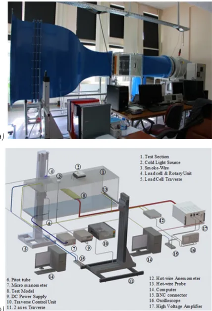
The experiments were conducted on a wind tunnel with a test section of 570 mm × 570 mm × 1000 mm. In Fig. 1 the test model and experimental setup of plasma actuator are illustrated. The NACA0015 airfoil is used as a test model in the experiments at
ReC = 48000. The chord length and spanwise length of
the airfoil are 150 mm and 540 mm, respectively.
Fig. 1. The test model and experimental setup of plasma actuator
As it is seen in Fig. 2 three different electrode geometry configurations namely as linear, saw-tooth and square types are illustrated. The plasma actuators
were mounted horizontally on the NACA0015 airfoil
at x/C = 0.1 where “x/C” denotes dimensionless
distance. Each plasma actuator consists of embedded and exposed electrodes. The dielectric material, Kapton, is a dielectric tape with thicknesses of 0.07 mm and it is placed between plasma electrodes.
The force measurement system devices and plasma production system devices are illustrated in Fig. 3. A custom-made power amplifier is used to produce the voltage required for plasma generation. The applied plasma voltage and the frequency are set to 7 kVpp and 3.5 kHz, respectively.
a)
b)
Fig. 3. a) General and b) schematic view of the test setup
The sinusoidal signal waveform is measured by using Tektronix TDS2012B model oscilloscope. The applied voltage is monitored by Tektronix P6015A model voltage probe connected to the oscilloscope.
An ATI Gamma model six axes load cell is used to measure the drag and the lift forces. Test model mounted on a rotary unit to adjust the attack angle of the model. Measurements were taken at 1000
Hz sampling frequency during 10 second period.
Therefore, 10000 sampled values were taken for each measurement and it was repeated twice for each experimental testing session. In order to calculate the net drag forces acting on the airfoil, drag of endplates, holder rod, connector between model and holder rod were exiled from total drag forces.
2 RESULTS AND DISCUSSION
The effects of the plasma actuators shapes placed along the span length of the NACA0015 airfoil are investigated. Three different electrode geometry configurations, linear, saw-tooth and square, are used for the experiments. The plasma actuators were
activated at 3.5 kHz excitation frequency and 7 kVpp
applied voltage. As it is seen from Fig. 4, the stall angle is shifted from 8° to 10° by using linear and saw-tooth plasma actuators compared with the no plasma condition on the airfoil at Re = 4.8 × 10⁴. The square
shaped plasma actuator is not effective for delaying stall angle for the same experimental parameters. On the one hand, for the attack angle of 8°, the lift coefficient value is observed to be increasing from 0.70 to 0.80 (approximately 15 % increase) when a saw-tooth shaped plasma actuators is used. The use of a linear plasma actuator appears to increase the lift coefficient approximately by 8 % at the same attack angle. On the other hand, the use of square shaped plasma actuator leads to reduction in lift coefficient of the airfoil. For the attack angle of 10°, the lift coefficient is increased from the value of 0.49 to 0.94 (approximately 91 %) by saw-tooth shaped plasma actuators. The performance enhancement achieved in lift coefficient using the saw-tooth shaped plasma actuator appears to be the same as that of the linear plasma actuators.
Fig. 4. Effect of the electrode geometry on lift coefficient of the
As seen from Fig. 5 the use of square shaped and linear plasma actuators leads to reduction in drag. However, there does not appear to be a significant effect in reduction of the drag coefficient for the saw-tooth shaped plasma actuators.
Fig. 5. Effect of the electrode geometry on drag coefficient
of the NACA0015 airfoil
The maximum reduction in drag of (about 31 %) is observed at the attack angle of 10° for the square shaped plasma actuators. For the same plasma actuator, the drag coefficient is decreased about 34 % at the attack angle of 12°.
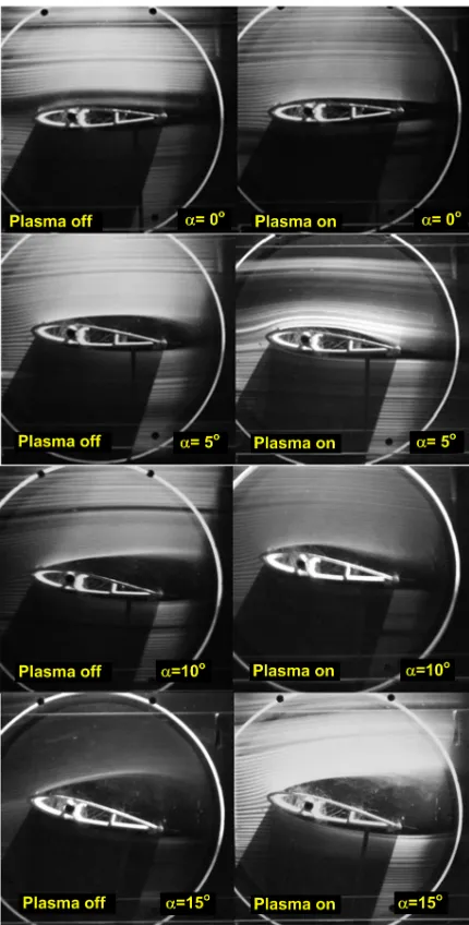
In Figs. 6, 7 and 8, flow visualization of the
NACA0015 aircraft wing is performed by the smoke-wire method. For the attack angle of the airfoil at 0, 5, 10 and 15 degrees, flow structure around the airfoil and wake region of the airfoil are observed with the help
of the flow visualization method. In Fig. 6, the flow visualization results are presented where the cases of
the plasma-off and plasma-on are seen clearly. The induced flow is generated by activating the plasma actuator. This induced flow adds momentum to the separated flow. The separated flow is reattached to the surface of the airfoil with the help of the induced flow.
The plasma actuator appears to be completely controlling the flow around the airfoil at the attack angle of 5°. In addition, the separated flow seems to be reattached to the surface of the airfoil. It is observed that the separated flow is reattached to the surface of the airfoil by the activated plasma actuator at attack angle of 10°. However, with increasing attack angle of the airfoil, the effectiveness of the plasma actuator is decreased. At the attack of 15°, the separated flow is not efficiently reattached the flow to the airfoil surface. This is mainly due to the fact that the plasma actuator placed in the x/C = 0.1 position is not close enough to the separated flow to reattach it to
the surface. Hence, for the saw-tooth and the square plasma actuator models, it was unnecessary to obtain
flow visualization by the smoke-wire method at the attack angle of 15°. Fig. 7 shows the flow visualization
results for square shaped plasma actuator where cases of plasma-on and plasma-off are presented. The flow
visualization is performed at Re = 2.5 × 10⁴ when the
applied plasma voltage and the excitation frequency
are set to 7 kV and 3.5 kHz, respectively.
The separated flow is reattached to the surface of the airfoil at the attack angle of 5°. The reattachment of the separated flow is achieved due to the induced flow and the 3D flow structure effects. The square
shaped plasma actuator is less effective in reattaching the flow to the surface of the airfoil than that of the linear plasma actuator. In square-shaped plasma actuators, the air passing sliding over the surface of the electrodes is held on the electrode surfaces due to induced flow effect of the plasma. However, the air that passes through the gap between the electrodes flows freely. The air that passes through the gap between the electrodes interact with the air flow sliding over the electrode surface that leads to 3D flow structure. At the attack angle of 10°, it is observed that the airfoil reaches to its stall angle. Due to the plasma actuators casing the separated flow become closer to the surface of the airfoil, thus, the stall angle is shifted further.
Fig. 8 illustrates the flow visualization results for
the cases of the plasma-off and plasma-on for the saw-tooth shaped plasma actuator. It has been observed that the square and saw-tooth shaped plasma actuator models appear to show similar results in the way they affect the flow. They both force the flow to reattach onto the model surface. The plasma generated by these models also appears to form a 3D flow structure
around the airfoil. Comparing the flow visualization
results of these two plasma actuators, it is observed that the saw-tooth shaped plasma actuators are far more effective on reattachment of the separated flow onto the model surface. For attack angle of 5° and 10°, this result can be clearly seen from the flow
visualization results of the comparison of the relevant
plasma actuators.
In Table 1, all the experimental results shown in
Figs. 4 and 5 are summarized where the results for
comparison of plasma actuators are presented. As seen
Fig. 7. Visualized flow around the NACA0015 airfoil for V = 7 kVpp and f = 3.5 kHz at Re = 25000 (square electrodes)
Fig. 8. Visualized flow around the NACA0015 airfoil for V = 7 kVpp and f = 3.5 kHz at Re = 25000 (saw-tooth electrodes)
Table 1. Plasma actuators and their effect on flow properties
Actuators Plasma off Linear Square Saw-tooth
Aerodynamic properties
-Stall angle 8° 10° 8° 10°
CL 0.5 0.9 0.65 0.95
from Table 1, linear and saw-tooth plasma actuators appears to shift the stall angle about 2° and also increases in lift relative to the other two cases. The linear and square plasma actuators appear to decrease in drag relative to the other two cases. The studied plasma actuators seem to force the separated boundary layer come closer to the airfoil surface due to the effect of induced flow generated and this seems to increase the lift coefficient considerably. The results indicate that, the plasma actuators of square, linear and saw-tooth models increase the lift coefficient by 30 %, 80 % and 90 % relative to plasma-off case, respectively.
The saw-tooth plasma actuators appear to be more suitable for obtaining more lift force on take-off and reducing fuel consumption. However, it seems to be more convenient to use a square-shaped plasma actuator to reduce the drag force acting on the airfoil when there is no need for extra lifting force. This experimental study contributed to the determination of the plasma actuator geometry to be used according to the necessary conditions of the aircraft. In addition, the use of other models in comparison to conventional (linear) plasma actuators appears to reduce fuel consumption due to enhancement in aerodynamic efficiency.
3 CONCLUSIONS
In this study, the effects of the plasma actuator shapes placed along the span length of the NACA0015 airfoil are investigated at Re = 4.8 × 10⁴. Three different
electrode geometry configurations as linear,
saw-tooth and square are used for the experiments. The
plasma actuators are activated at 3.5 kHz excitation
frequency and 7 kVpp applied voltage. The lift and
drag coefficient of the airfoil are examined by varying
the attack angle. The following list of conclusions achieved:
• For the attack angle of 10°, the lift coefficient is increased approximately 91 % by saw-tooth shaped plasma actuators. Also, the linear plasma actuator enhanced the lift coefficient significantly. • The stall angle is shifted from 8° to 10° by using
linear and saw-tooth plasma actuators.
• The linear and square shaped plasma actuators also lead to more reduction in the drag than no plasma and saw-tooth shaped plasma actuators cases.
• The maximum reduction in drag is 31 % at the attack angle of 10° for the square shaped plasma actuators. For the same plasma actuator, the drag
coefficient is decreased 34 % at the attack angle of 12°.
4 ACKNOWLEDGEMENTS
The authors would like to acknowledge the financial support of this work by the Scientific Research Projects (BAP) of the Çukurova University under the Contact Number of FBA-2017-7111.
5 NOMENCLATURES
CD drag coefficient, [-]
CL lift coefficient, [-]
C chord length, [mm]
x actuator position, [mm]
Re, ReC Reynolds number, [-]
α attack angle, [º]
x/C dimensionless distance, [-]
kVpp peak to peak applied voltage, [kV]
6 REFERENCES
[1] Erfani, R., Erfani, T., Utyuznikov, S.V, Kontis, K. (2013). Optimisation of multiple encapsulated electrode plasma actuator. Aerospace Science and Technology, vol. 26, no. 1, p. 120-127, DOI:10.1016/j.ast.2012.02.020.
[2] Hale, C., Erfani, R., Kontis, K. (2010). Plasma actuators with multiple encapsulated electrodes to influence the induced velocity. 48th AIAA Aerospace Sciences Meeting Including
the New Horizons Forum and Aerospace Exposition, DOI:10.2514/6.2010-1223.
[3] Akansu, Y.E., Karakaya, F., Şanlısoy, A. (2013). Active control of flow around NACA0015 airfoil by using DBD plasma actuator.
EPJ Web of Conferences, vol. 45, no. 01008, DOI:10.1051/ epjconf/20134501008.
[4] Zhang, P.F, Liu, A.B., Wang, J.J. (2009). Aerodynamic modification of a NACA 0012 airfoil by trailing-edge plasma Gurney flap. AIAA Journal, vol. 47, no. 10, p. 2467-2474 DOI:10.2514/1.43379.
[5] Wang, C.C., Durscher, R., Roy, S. (2011). Three-dimensional effects of curved plasma actuators in quiescent air.
Journal of Applied Physics, vol. 109, no. 8, p. 083305, DOI:10.1063/1.3580332.
[6] Roy, S., Wang, C.C. (2009). Bulk flow modification with horseshoe and serpentine plasma actuators. Journal of
Physics D: Applied Physics, vol. 42, no. 3, p. 032004, DOI:10.1088/0022-3727/42/3/032004.
[7] Akbıyık, H., Akansu Y.E., Yavuz, H. (2017). Active control of flow around a circular cylinder by using intermittent DBD plasma actuators. Flow Measurement and Instrumentation, vol. 53, part B, p. 215-220, DOI:10.1016/j.flowmeasinst.2016.12.008. [8] Bhattacharya, S., Gregory, J.W. (2015). Effect of
[9] Bhattacharya, S., Gregory, J. (2013). The optimum wavelength of spanwise segmented plasma actuator forcing of a circular cylinder wake. 51st AIAA Aerospace Sciences Meeting
including the New Horizons Forum and Aerospace Exposition, no. AIAA 2013-1011, DOI:10.2514/6.2013-1011.
[10] Lu, Z., Wong, C.W., Wang, L., Alam, M.M., Zhou, Y. (2016). Separation control on a NACA0015 airfoil with plasma-actuator-generated disturbance. 8th AIAA Flow Control Conference, DOI:10.2514/6.2016-3625.
[11] Belan, M., Messanelli, F. (2015). Compared ionic wind measurements on multi-tip corona and DBD plasma actuators.
Journal of Electrostatics, vol. 76, p. 278-287, DOI:10.1016/j. elstat.2015.06.008.
[12] Berendt, A., Podliński, J, Mizeraczyk, J. (2011). Comparison of airflow patterns produced by DBD actuators with smooth or saw-like discharge electrode. Journal of Physics: Conference
Series, vol. 301, no. 1, p. 012018, DOI:10.1088/1742-6596/301/1/012018.
[13] Liu, Z.F., Wang, L.Z., Fu, S. (2011). Study of flow induced by sine wave and saw tooth plasma actuators. Science China Physics, Mechanics and Astronomy, vol. 54, no. 11, p. 2033-2039, DOI:10.1007/s11433-011-4511-x.