Materials Science and Engineering Publications
Materials Science and Engineering
5-2004
The role of melt pool behavior in free-jet melt
spinning
Ralph E. Napolitano
Iowa State University, ren1@iastate.edu
H. Meco
Iowa State University
Follow this and additional works at:
http://lib.dr.iastate.edu/mse_pubs
Part of the
Metallurgy Commons
The complete bibliographic information for this item can be found at
http://lib.dr.iastate.edu/
mse_pubs/163
. For information on how to cite this item, please visit
http://lib.dr.iastate.edu/
howtocite.html
.
The influence of melt pool behavior on the competition between the nucleation of crystalline solidification products and glass formation is examined for an Fe-Si-B alloy. High-speed imaging of the melt pool, analysis of ribbon microstructure, and measurement of ribbon geometry and surface character all indicate upper and lower limits for melt spinning (MS) rates for which fully amorphous ribbons can be achieved. Comparison of the relevant time scales reveals that surface-controlled melt pool oscillation may be the dominant factor governing the onset of unsteady thermal conditions accompanied by varying amounts of crystalline nucleation observed near the lower limit. At high rates, the influence of these oscillations is minimal due to very short melt pool residence times. However, microstructural evidence suggests that the entrapment of gas pockets at the wheel-metal interface may play a critical role in establishing the upper rate limit. An observed transition in wheel-side surface character with an increasing MS rate supports this contention.
Keywords
Ames Laboratory, Materials and Engineering Physics
Disciplines
Metallurgy
Comments
This article is fromMetallurgical and Materials Transactions A35 (2004): 1539,doi:10.1007/ s11661-004-0261-y. Posted with permission.
Rights
The Role of Melt Pool Behavior in Free-Jet Melt Spinning
R.E. NAPOLITANO and H. MECO
The influence of melt pool behavior on the competition between the nucleation of crystalline solidification products and glass formation is examined for an Fe-Si-B alloy. High-speed imaging of the melt pool, analysis of ribbon microstructure, and measurement of ribbon geometry and surface character all indicate upper and lower limits for melt spinning (MS) rates for which fully amorphous ribbons can be achieved. Comparison of the relevant time scales reveals that surface-controlled melt pool oscillation may be the dominant factor governing the onset of unsteady thermal conditions accompanied by varying amounts of crystalline nucleation observed near the lower limit. At high rates, the influence of these oscillations is minimal due to very short melt pool residence times. However, microstructural evidence suggests that the entrapment of gas pockets at the wheel-metal interface may play a critical role in establishing the upper rate limit. An observed transition in wheel-side surface character with an increasing MS rate supports this contention.
I. INTRODUCTION
T
HE techniques of rapid solidification continue to be of central interest because of their utility in producing materials with microstructures and properties unattainable through other methods. Accordingly, the literature contains numerous reports of ultra-refined microstructures,[1]growth mode transitions,[2]anomalous solubility,[3]and the presence of metastable phases,[4]
all achieved through these methods. More generally, the con-ditions that prevail during a process such as melt spinning (MS) offer an opportunity to study various mechanisms of alloy solidification at the high-rate extreme. Of course, the careful experimental study of solidification dynamics is impeded by a generally poor understanding of the local conditions that exist within the melt pool. Such difficulties highlight the demand for modeling tools capable of handling the complex problems of heat transfer, fluid flow, and interfacial behavior that dominate the MS process. Indeed, as our ability to pre-dict the local thermal conditions improves, the kinetics of the operative nucleation and growth processes can be better quantified. Because of the interdependence between local con-ditions and microstructural dynamics, the investigation of nucle-ation and growth during MS not only serves to enhance our understanding of solidification dynamics, but may also provide a means to understand better the evolution of local conditions within the melt pool. It is in this iterative sense that the current observations and interpretations of melt spun structures are offered. The Fe-Si-B system is employed for the experimental work. There is considerable interest in the melt spun microstruc-tures in these alloys because of the magnetic properties that may be exhibited after rapid solidification.5,6
The rapid solidification technique of MS arises from the general method known as splat-quenching, in which a mass of molten metal is dropped onto a chill block of much larger thermal mass and immediately quenched. This is essentially
a direct-chill casting process in which the chill is large enough, compared to the specimen, that virtually all of the latent heat liberated by the freezing liquid metal is absorbed instanta-neously by the chill. Because the splat-quenching technique is limited by heat transfer across the metal-chill interface and by heat conduction both within the freezing metal and within the chill, only very small specimens can be rapidly solidified in this manner. Such limitations are reduced sub-stantially in the MS process, for which a rotating wheel or drum is employed as the chill block. The rotating chill block permits a much larger mass to serve effectively as the chill, and the relative motion between the wheel and the metal mechanically promotes heat transfer across the interface. By forcing a controlled stream of molten metal onto the rotating wheel, a large volume of material can be rapidly solidified, and estimated cooling rates of 106to 109K/s are typical.[7]
Two basic varieties of the MS process have emerged, based primarily on the position of the crucible with respect to the rotat-ing chill surface. In the process known as planar flow casting, the melt is essentially held in contact with the chill, and a thin film or ribbon is drawn out by the rotating wheel. In the process known as free-jet w, a stream of molten metal is poured or injected under pressure so that it strikes the rotating wheel with some incident velocity. In the current article, we consider only the latter process. As in all solidification processes, the resulting structure is governed largely by the competition between various nucleation and growth mechanisms. In many casting processes, the conditions which give rise to nucleation may be selectively promoted or suppressed, and the microstructure can be controlled accordingly. Indeed, a full range of microstruc-tures between fine-grain polycrystalline castings and mono-grain or single-crystal castings is readily accessible, and such control has largely been reduced to an engineering problem. This is far from the case for the MS process, where the thermal con-ditions are neither easily controlled nor well understood. Various modeling approaches and analytical treatments have made some progress toward the general prediction of thermal conditions within the melt pool.[8–17]Since MS is often implemented to
achieve rates sufficiently high to avoid nucleation altogether, resulting in an amorphous or glassy ribbon, nucleation control is of primary importance. However, nucleation kinetics are generally very sensitive to local temperature, with volumetric nucleation rates generally varying as exp(1/TT2), and
R.E. NAPOLITANO, Assistant Professor, Department of Materials Science and Engineering, Iowa State University, is Associate Scientist, Materials and Engineering Physics Program, Ames Laboratory, United States Department of Energy, Iowa State University. Contact e-mail: ralphn@iastate.edu H. MECO, Graduate Research Assistant, is with the Department of Mater-ials Science and Engineering, Iowa State University, Ames, IA 50011.
Manuscript submitted June 5, 2003.
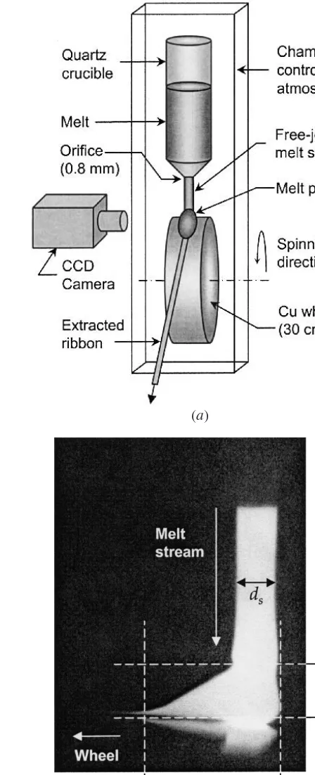
(a)
(b)
Fig. 1—(a) Arrangement of the melt spinning apparatus and subsidiary equipment for melt pool imaging. (b) Typical image of the melt pool during melt spinning indicating the melt pool height, hm, the melt pool length, lm,
and the diameter of the incoming melt-stream, ds.
microstructural control remains problematic. To this end, we offer several observations regarding nucleation and growth dur-ing the MS of Fe-Si-B alloys, with the intent that these may provide some insight into the important effects of fluid flow and gas entrapment as they become significant factors in the melt pool within different regimes of quench-wheel velocity.
II. EXPERIMENTAL
The scope of experiments reported here includes (1) the MS of a set of alloy ribbons using a range of quench-wheel velo-cities, (2) the in-situoptical imaging of the melt pool during the MS process, (3) the post-solidification characterization of ribbon geometry, and (4) the characterization of microstructure in the melt spun ribbons. Experimental details concerning the test materials, solidification techniques, and analysis methods are given here.
A free-jet MS process was employed, as illustrated schemat-ically in Figure 1. All ribbons were made from Fe-10at% Si-15at%B, prepared by vacuum/argon arc-melting on a water-cooled copper hearth. Each melt spun ribbon was produced using a total alloy charge of approximately 10g, melted by vac-uum induction within the MS chamber, heated to a superheat of 100 K under 3.0 104Pa (0.3 atm) He, and pressure-injected
through a 0.8-mm orifice onto a 0.3-m diameter rotating copper quench wheel. An injection pressure differential of 1.7 104Pa
between the melt crucible and the chamber was maintained with an argon gas overpressure. Tangential wheel velocities of 4 to 40 m/s were used, producing melt spun ribbons nomi-nally 1 mm in width and 0.03 to 0.14 mm in thickness.
High-speed optical imaging of the liquid metal impingement site was utilized to examine the influence of wheel speed on melt pool shape and to reveal the changes in melt pool shape that occur during the MS process. Images were obtained with a 12-bit 640480 pixel CCD camera, situated with the optical axis coincident with the wheel surface and parallel to the axis of wheel rotation. This arrangement is illustrated in Figure 1, along with a typical optical image of the melt pool. Such images were recorded at 35 frames/s, using a shutter speed (exposure duration) of 2104seconds. For the conditions used here, the
typical MS “run” duration was approximately 2.0-2.5 seconds, with 60 to 75 images being acquired for each run. Image seq-uences were analyzed for quantitative measurement of the length (lm) and height (hm) of the melt pool, as defined in Figure 1.
Both optical and scanning electron microscopy were used to observe the general appearance of both the free-side and wheel-side surfaces of the melt spun ribbons. Wheel-side sur-faces were examined further using high-resolution contact-stylus profilometry. Ribbon thickness and its variation along the MS direction were measured using a mechanical micro-meter. Uniformity of ribbon width was quantified through the digital analysis of optical images of long (0.2 to 1.0 m) sections of ribbon. Internal and surface microstructures were investigated using optical microscopy and scanning electron microscopy. In addition, transmission electron microscopy and X-ray diffraction were used to characterize constituent phases.
III. MICROSTRUCTURAL RESULTS
Since the ultimate motivating factor in the study of melt pool behavior during MS is the prediction and control of
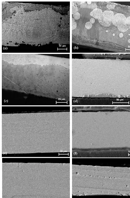
[image:4.684.322.546.42.593.2]Fig. 2—Microstructure on axial cross sections of ribbons melt spun at wheel speeds of (a) 4 m/s, (b) 5 m/s, (c) 7 m/s, (d) 7.5 m/s, (e) 10 m/s, (f) 20 m/s, (g) 30 m/s, and (h) 40 m/s. For each image, the wheel-side surface is at the bottom. All images are backscattered electron images, except for (b) and (c), which are optical images.
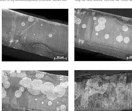
Fig. 3—Nonuniform distribution of crystalline constituent observed on the axial cross section of a ribbon melt spun at 5 m/s. The wheel-side surface is at the bottom. (Optical images, Nital etch.)
exhibit no evidence of crystalline phase formation. Exami-nation of ribbons produced at lower wheel speeds, however, reveals the expected transition from amorphous to crystalline material, with the crystalline fraction increasing with decreas-ing wheel speed. At 7.5 m/s, a sparse distribution of small particles or “nodules” is observed along the wheel-side sur-face of the ribbon, but at lower wheel speeds, substantial internal nucleation is observed. Figure 2 shows a microstruc-ture that is nearly 100 percent crystalline for 4 m/s. It should be noted here, however, that the microstructures are extremely nonuniform. For example, several microstructures observed within a single ribbon, melt spun at 5 m/s, are shown in Figure 3. These range from nearly fully amorphous to fully crystalline, suggesting severely nonuniform cooling condi-tions in the ribbon.
Detailed views of the wheel-side surface and axial cross section are presented in Figure 4, for the 7.5-m/s ribbon. This figure shows that the crystalline constituents appear as very fine multiphase cellular or lamellar solidification products with microstructures suggesting that each nodule has grown radi-ally outward from a single nucleation point, with a nearly isotropic velocity. Also shown is a transmission electron image of the crystalline constituents and the associated electron dif-fraction patterns, indicating the presence of bcc-Fe, Fe3B, and
Fe2B phases. X-ray diffraction patterns from near-surface
scat-tering on the wheel-side of the ribbons are shown in Figure 5, also revealing an increasing presence of the bcc-Fe phase as the wheel speed is decreased below 10 m/s.
The transition from the amorphous ribbons observed at wheel speeds of 10 to 30 m/s to crystalline ribbons at 5 m/s is not surprising and could be described solely by the wheel-speed dependence of the cooling rate in the freezing liquid. Accordingly, a minimum wheel speed (corresponding to a minimum cooling rate) for the formation of glassy ribbons would be indicated. However, the dramatic nonuniformity, which may itself be critical to the transition, would not be explained by such a simple description.
and ultimately resulting in a transition to crystalline phase formation at high wheel speeds.
It is our contention that local thermal transients arising from unsteady melt pool behavior and the entrapment of gas at the melt-wheel interface play a critical role in establishing these
observed regimes of nucleation behavior. In the sections that follow, we examine the melt pool shape, the ribbon geo-metry, and the ribbon surface character over the range of wheel speeds and consider the influence of melt pool shape dyna-mics on the ultimate nucleation behavior during the MS process.
IV. FURTHER RESULTS, ANALYSIS,
AND DISCUSSION
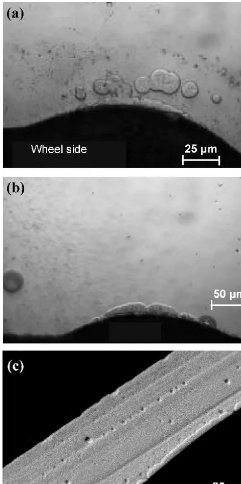
[image:7.684.52.292.35.594.2]We examine briefly the distribution of surface nodules in ribbons produced at wheel speeds below the onset of observed crystalline solidification. Just below this onset, the multi-phase nodules are observed to nucleate rather sparsely and only on the wheel-side surface, growing as nearly perfect hemispheres unless altered by impingement. The generally random spatial distribution of the nodules on the wheel-side surface indicates that nucleation proceeds in a largely random fashion. An observed exception to the random distribution is that groups or clusters of nodules are observed near anom-alies in the wheel-side surface. As evidence of such prefer-ential nucleation, Figure 6 shows clusters of nodules adjacent to relatively deep pockets (0.03 mm) in the wheel-side surface of selected ribbons. Indeed, close inspection of this figure reveals that the long chains of crystalline particles observed in the 40-m/s ribbon are also associated with anomalies in the wheel-side surface, although the gas pockets are very long and not as easily observable.
Fig. 4—Representative views of the multiphase crystalline nodules observed (a) on the wheel-side surface, (b) on an axial cross section of the Fe75Si10B15
ribbon melt spun at Vw7.5 m/s (backscattered electron images, Nital
[image:7.684.318.553.39.330.2]etch), and (c) in a TEM bright-field image showing the multiphase struc-ture of the nodules with the corresponding selected-area diffraction pattern.
Fig. 5—X-ray (Cu K) diffraction patterns from ribbon wheel-side surfaces
reveal crystalline Fe (bcc) peaks for high and low wheel speeds (7.5 and 40 m/s). At intermediate wheel speeds, only amorphous peaks are observed (10, 20, and 30 m/s).
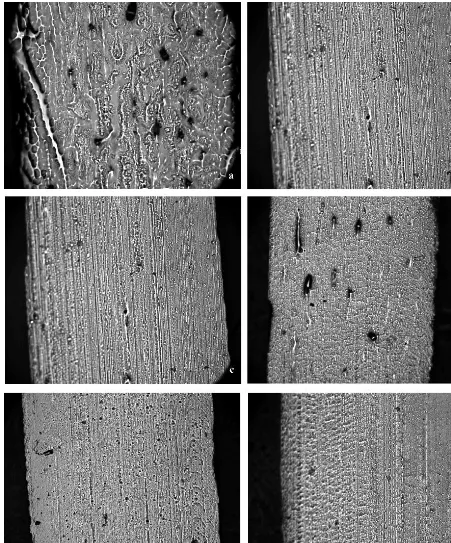
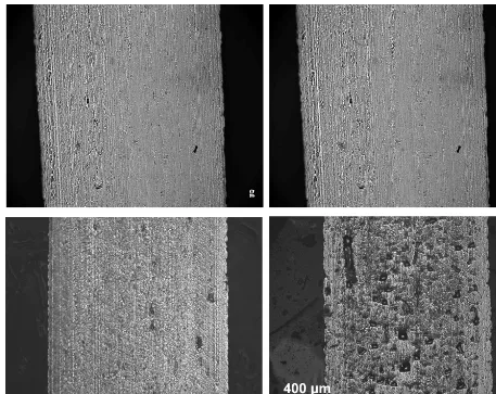
Along with the surface nucleation of the multiphase nodules, examination of the wheel-side ribbon surfaces indicates a sig-nificant variation in general surface roughness with wheel speed. Optical images of the wheel-side surfaces from ribbons produced with wheel speeds ranging from 5 to 40 m/s are shown in Figure 7. The dramatically different appearance of these surfaces with an increase in roughness at both low and high speeds suggests the existence of three distinct regimes of melt pool behavior. To better characterize the differences in the wheel-side surfaces apparent in Figure 7, contact pro-filometry was performed, yielding quantitative surface rough-ness measurements for selected melt spun ribbons. For each
specimen, multiple parallel height profiles were obtained along the MS direction (axial), and the associated topographic rep-resentations of selected portions of the wheel-side surfaces were constructed, as shown in Figure 8. Each profile was ana-lyzed to determine several roughness parameters, which, in turn, were averaged over many axial profiles. The roughness parameter Rais defined as the deviation from the mean
pro-file height averaged over the analysis length, la,
[1]
where y(x)is the surface height profile. The parameter Ra
is plotted vs wheel speed in Figure 9. This figure clearly shows that the surface roughness passes through a minimum between 20 and 30 m/s and that Ra increases rapidly on
either side of this range. Also plotted here is Rq, the
root-mean-square of the deviation from the mean height,
[2] Significant, perhaps, is that Rqincreases more rapidly than
does Raat high wheel speeds, indicating the presence of more
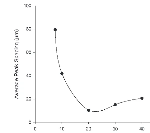
severe peaks and valleys on the surface. This is consistent with the appearance of the surface reconstructions in Figure 8. The average peak spacing ais plotted in Figure 10, once again
showing a minimum between 20 and 30 m/s. In addition, a
increases very rapidly with decreasing wheel speed but increases much more modestly at high wheel speeds, indicating that the increase in roughness that is observed at the two extremes may originate from different sources. Looking into this issue further, we examine the areal distribution of surface height, for the wheel-side surface. Such distributions are plotted in Figure 11 for wheel speeds of 7.5, 20, and 40 m/s. In each curve, a linear region can be identified, along with deviations from linearity on either side of this region. The width of the linear region is given by Rk, while the width of the high-end
and low-end nonlinear “tails” are given by Rpkand Rvk,
respec-tively. These three parameters are plotted as a function of wheel speed in Figure 12. Of interest here is that Rpktracks nicely
with Rk, indicating that the linear and upper portions of the
distribution remain mathematically similar over the range of wheel speeds. This is not the case for Rvk, which increases
dis-proportionately at high wheel speeds, indicating an increase in valley “basin” area. This change in the general surface char-acter may indicate a transition in the behavior of the melt pool in terms of its interaction with the wheel. Notably, the increase in Rvkis coincident with an increase in observed surface
pock-ets (Figure 6), which presumably are associated with the entrap-ment of gas at the liquid-wheel interface, resulting locally in less efficient cooling of the adjacent metal.
These observations suggest that anomalies in the wheel-side surface of the ribbon, which may arise from a number of phenomena including melt pool oscillations, turbulence, and trapped gas, may influence the local thermal condi-tions sufficiently to affect a detectable change in nucle-ation behavior. This implies that the control of the molten metal pool is critical for reproducible solidification during
RqG
1
la
la0
[y(x)y]2dx.
Ra
1
la
la0
0
y(x) y0
dx, [image:8.684.54.294.39.521.2]y
MS. Furthermore, the description of the prevailing solidifi-cation conditions, necessary for the effective prediction and control of microstructure, requires an understanding of melt pool dynamics and stability. This, in turn, calls for reliable estimates of physical parameters such as surface energy and viscosity, along with better descriptions of velocity-dependent heat transfer at the interface between the liquid metal and the spinning quench wheel.
Presuming that the influence of melt pool behavior can be observed in the overall ribbon geometry and wheel-side surface appearance, we examine various geometric features here. Indeed, it has been shown that variations in ribbon width and thickness may be caused by oscillations in the injection stream and melt pool.[18]Measurements of average ribbon
[image:9.684.79.530.39.582.2]thickness, taken on the ribbon midplane, are plotted in Figure 13 as a function of wheel speed. In this figure, the 95 percent
Fig. 7—Wheel-side surface images of ribbons melt spun at wheel speeds of (a) 5 m/s, (b) 6 m/s, (c) 7 m/s, (d) 7.5 m/s, (e) 8 m/s, (f) 9 m/s, (g) 10 m/s, (h) 20 m/s, (i) 30 m/s, and (j) 40 m/s. The spinning direction is vertical in the figure. All images are at the same magnification.
Fig. 7—(Continued). Wheel-side surface images of ribbons melt spun at wheel speeds of (a) 5 m/s, (b) 6 m/s, (c) 7 m/s, (d) 7.5 m/s, (e) 8 m/s, (f) 9 m/s, (g) 10 m/s, (h) 20 m/s, (i) 30 m/s, and (j) 40 m/s. The spinning direction is vertical in the figure. All images are at the same magnification.
confidence intervals indicate the very low variance in the overall thickness. Thickness profiles, showing the spatial (and corresponding temporal) variation in ribbon thickness along the spinning direction, were measured over total lengths rang-ing from 60 to 250 mm, dependrang-ing on the wheel speed, as shown in Figure 14.
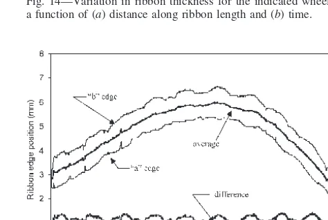
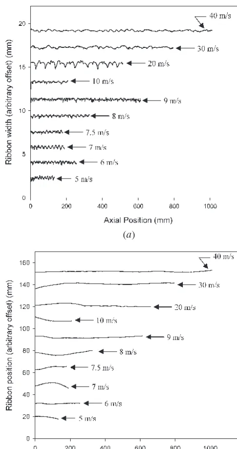
Variation in ribbon width was measured through the analysis of optical images of projected ribbon silhouettes. Typical ribbon-edge traces for a single image (for the ribbon melt spun at 7 m/s) are shown in Figure 15. The traces labeled (a) and (b) indicate the two ribbon edges. Also shown is the aver-age of the two edge traces and the difference between the two edge traces. Clearly, there are two characteristic types of vari-ation observed in the ribbon footprint. The first is the oscil-lation in the ribbon position as indicated by the “average” trace in Figure 15. The second is the oscillation in the ribbon width as indicated by the “difference” trace. Variation in rib-bon position and width were measured in this way along the spinning direction, and the resulting profiles are plotted in Figure 16. For each of the width profiles, the dominant wave-lengths were identified using a fast-Fourier-transform algo-rithm. These wavelengths are plotted as a function of wheel speed in Figure 17. The linear behavior observed here reveals the existence of a characteristic temporal period rather than a characteristic spatial wavelength. The characteristic frequency
was determined to be 314 s1(period of 3.2 ms) from the
lin-ear slope in Figure 17. Further evidence of this particular dom-inant mode is provided in Figure 18, where the ribbon width and position profiles are plotted as a function of time rather than distance. The Fourier transforms of the width-time curves are shown in Figure 19, revealing that the dominant oscillation frequency of approximately 314 s1is, indeed, independent
of wheel speed. Such distinct time dependence indicates that the observed variations are related to the dynamics of the melt pool and injection jet and that they are not directly linked to anomalies in the wheel surface or any other rotational excitations.
The effect of melt pool oscillation on the melt spun ribbon uniformity has been discussed in some detail by Anthony and Cline,[18]where the melt pool was treated as an oscillating
spherical droplet. Indeed, the characterization of oscillation modes in levitated droplets is a well-established technique for the measurement of surface energy.[19–23]We take a similar
approach, with radial variation described as
[3] where r0is the mean radius of the melt pool, nis the nth
mode amplitude of oscillation, tis time, nis the nthmode
[image:10.684.78.535.37.400.2]Fig. 8—Representative images of wheel-side surface reconstructions from pro-filometry measurements. Represented ribbons were melt spun at (a) 7.5 m/s, (b) 20 m/s, and (c) 40 m/s. The spinning direction is indicated by arrows.
[image:11.684.54.294.40.301.2]Fig. 9—The average roughness parameters, Raand Rq, vswheel speed.
Fig. 10—The average peak spacing, a, vswheel speed.
Fig. 11—Areal distribution of wheel-side surface elevation for ribbons melt spun at 7.5 m/s, 20 m/s, and 40 m/s.
consider the axisymmetric modes (Yn) for which the
angu-lar frequency is given by
[4] where is the surface energy and Mis the mass of the oscil-lating liquid.[24]
In the case of MS, any oscillation mode can be correlated to a variation in the eventual ribbon geometry through the wheel velocity. Thus, the spatial variation in the ribbon width
vn2n(n1)(n 2)
4p
3
s
M
along the MS (x)direction is simply given by making the substitution t x/Vw, where Vwis the tangential velocity
of the wheel surface. Hence, the variation in ribbon width
Wmay be described by
[5] where the amplitude prefactor ndepends on the geometry
of the melt pool, the nthmode wavelength is given by
[6] and the nthmode frequency v
nis equal to n/2.
We now examine the observed oscillatory behavior within the framework of this theoretical treatment. For the purpose
ln Vw
vn W(x)2cr0 nYn sin a
2px
ln b d
[image:11.684.318.553.288.500.2] [image:11.684.53.293.356.567.2](a)
[image:12.684.313.555.36.490.2](b)
[image:12.684.53.290.38.252.2]Fig. 14—Variation in ribbon thickness for the indicated wheel speeds as a function of (a) distance along ribbon length and (b) time.
Fig. 15—Ribbon edge traces (aand b) along with average ((a b)/2) and difference (ba) traces for the ribbon melt spun at 7 m/s.
Fig. 13—Average ribbon thickness vswheel speed, from thickness profiles measured on the midplane, along the spinning direction.
of estimating the mass of the melt pool, we assume that the cross-sectional shape is semielliptical on any x x0plane.
We note that the height of the melt pool is constant and equal to hmunder the incoming melt stream and that it varies
from hmto zero along the xdirection, as shown in Figure 1.
Thus, the cross-sectional melt pool shape on any arbitrary transverse plane is given by
[7]
where h0(x0) is the midplane melt pool height at any xx0.
We further assume, based on in-situ imaging of the melt
h(x0, y)h0(x0)a1
[image:12.684.53.294.297.508.2]4y2 W2b
[image:12.684.318.555.534.693.2]Fig. 16—Variation of (a) ribbon width and (b) ribbon position along the melt spinning axial direction.
(b) (a)
pool shape, that h0varies linearly with xand is defined over lmas
(0 x ds) [8]
[9] Substituting Eqs. [8] and [9] into [7] and integrating, the mass of the melt pool is computed as
[10] Finally, Eq. [10] is substituted into Eq. [4] to compute the expected frequency for any axisymmetric mode, using the measured values of hm, lm, and W. Without an independently
determined surface energy for this particular Fe-Si-B alloy,
Mp
8hmrmW(lm ds).
h0(x)hmc1 a xds lmdsb d
.
(dsxlm) h0(x)hm
Fig. 17—Characteristic wavelength of ribbon width oscillations vswheel speed. A linear fit yields the common characteristic frequency of 314 s1.
we employ the value of 1.2 N/m, measured for the com-position Fe78Si9B13.[25]In addition, we take the density of the
melt as 7400 kg/m3.[26]The results of such calculations,
uti-lizing the measured values of lm, hm, and Wfor several wheel
speeds, are shown in Figure 19 for n2, 3, 4, 5, and 6. These are compared with the Fourier spectra obtained from analy-sis of the measured ribbon width. Despite the rather crude treatment presented here, the dominant frequency observed for every wheel speed examined generally lies between the predictions for n2 and n3, the most fundamental modes possible. This result is consistent with various prior reports of melt pool oscillation.[27–33]More important than the
speci-fic quantitative agreement is the observation of a spinning-rate-independent temporal wave number, suggesting that the melt pool may indeed be behaving in a manner similar to a freely oscillating droplet, at least to the extent that the dom-inant physical influence arises from the surface tension,* as
*Interestingly, this relationship between interfacial energy and wave number has recently been extended to atomic-scale fluctuations in rough crystal-melt interfaces and has provided a means for the theoretical pre-diction of interfacial energy as well as the anisotropy of interfacial energy with respect to crystal orientation.[34–37]
described by Rayleigh’s[23,24]equation
[11] which is identical to Eq. [4] for n 2. It should be stated, however, that the effects of specific melt pool geometry and temperature must be accounted for if more accurate quanti-tative descriptions of melt pool behavior are to be formulated, facilitating microstructural prediction.
The questions that naturally arise here relate to the source of the melt pool oscillation and to the ultimate influence on heat transfer and solidification. The observed characteristic oscillation modes are not coincident with any rotational fre-quency in the quench wheel. This does not necessarily exclude wheel-melt interactions from consideration as a potential source
s3
8pMvn
[image:13.684.318.558.36.242.2]Fig. 19—Fourier transform of ribbon width oscillation showing that the characteristic frequency is approximately 314 s1for all wheel speeds,
falling between predicted n2 and n3 oscillation modes.
Fig. 20—Typical melt pool images obtained by the in-situimaging tech-nique shown schematically in Fig. 1. The incoming melt stream is 0.8 mm in diameter.
of excitation for the observed melt pool oscillations. It does, however, suggest that the stable modes that ultimately govern the shape and, thus, the thermal conditions in the melt pool, are indeed dominated by the surface properties of the melt. Considering the concomitant changes in ribbon microstructure, the influence of these surface properties on the instability and dynamic behavior of the melt pool emerges as the critical factor in the establishment of local solidification conditions.
A complete understanding of melt pool dynamics would require detailed numerical simulation with proper treatment of surface tension and its influence on free boundary motion. However, observation of melt pool geometry and a simple comparison of the relevant time scales may provide a rea-sonable explanation for the observed range of wheel speeds for which effects of melt pool oscillation become important. In the discussion that follows, we examine the oscillatory
behavior of the melt pool irrespective of its origin, which may involve a number of sources, including instability of the incoming melt stream, vibration of the crucible, and unsteady injection pressure.
Using the high frame-rate in-situimaging technique dis-cussed earlier, melt pool shapes were obtained with a spa-tial resolution of 0.02 mm/pixel and a temporal resolution of 0.03 seconds. Typical images are shown in Figure 20 for wheel speeds varying from 5 to 40 m/s. Within the intermediate wheel-speed regime, which we have shown to yield amorphous ribbons with very low surface rough-(a)
[image:14.684.322.553.42.353.2](b)
[image:14.684.317.557.410.545.2]Fig. 21—Measured melt pool dimensions as defined in Fig. 1 vswheel speed.
Fig. 22—Residence time, tR, vswheel speed compared with the
oscilla-tion quarter-wavelength period, t1/4.
a long-wavelength variation in ribbon width. To identify the condition in which the residence and oscillation time scales are comparable and the influence of the periodic melt pool behavior becomes important, we employ the time period associated with the melt pool radius changing from the mean value to the maximum or minimum value, i.e., the quarter-wavelength time period. Figure 22 reveals that the residence time becomes equal to the quarter-wavelength period of 8 104seconds at a wheel speed of approxi-mately 8 m/s, which is consistent with the observed onset of unsteady melt pool behavior. Time-resolved measure-ments of lmare shown in Figure 23, along with two
corre-sponding sequences of images (for 7 and 10 m/s), revealing the change in the temporal behavior of the melt pool as the wheel speed is increased in this regime. Although the time resolution (0.3 seconds) is not sufficient to view the changes on the scale of the melt pool oscillations (8 104seconds), a clear picture does emerge. It appears that
traveling waves may be reinforced at low rates, where the residence time is high. It is also evident from this figure that the variance in lmchanges substantially between 7 and
10 m/s, which is supported by the measurements plotted in Figure 21.
V. SUMMARY
The evidence suggests that there exists a “window” of melt spinning rates suitable for obtaining amorphous ribbon. The presence of both upper and lower limits to this favor-able range of wheel speeds supports the contention that at least two different contributors play a critical role in the observed behavior and may influence the heat transfer over different regimes of wheel speed. Consistent with this evi-dence is the observation of three distinct velocity regimes of melt pool behavior, identified by ribbon geometry, surface roughness, and direct imaging of the melt pool shape. Indeed, these regimes have been shown to coincide with the MS rates associated with the observation of multiphase crys-talline nodules in the Fe-Si-B ribbons at both high and low MS rates.
A clear periodicity was observed in the ribbon width. The periodicity was shown to have a characteristic fre-quency (314 s1) rather than a characteristic spatial
wave-length. While the melt pool geometry is clearly different from that of a freely oscillating droplet, the oscillating sphere analysis employing a mass, corrected for the melt pool shape, indicates that the lowest order modes are oper-ative. Furthermore, the spinning-rate-independent charac-teristic frequency supports the assertion that the interfacial tension plays a dominant role in governing the melt pool dynamics.
Comparison between the oscillation time scale and the melt pool residence time reveals that, while the oscillations are present even at very high spinning rates, they have a significant effect on melt pool dynamics only in the low velocity regime and may be a key contributor to the unsteady behavior observed below 10 m/s. Indeed, this is supported by in-situimaging, showing that the transition to unsteady melt pool behavior occurs at wheel speeds consistent with the quarter-wavelength oscillation in the melt pool, deter-mined from the ribbon-width periodicity.
ness, the melt pool consists of a puddle beneath the incom-ing stream and a molten tail. Measurements of the length (lm) and height (hm) of the melt pool are plotted in Figure 21,
showing that the variation of hm is somewhat random
and lower in magnitude than that of lm, which clearly
increases with decreasing wheel speed. This results in a very rapidly increasing melt residence time as wheel speed is reduced, as shown in Figure 22. Considering now the oscillation of the melt pool with respect to this residence time, we see that, for high wheel speeds, the period of melt pool oscillation is much longer than the residence time. Therefore, the melt pool is relatively static for the time period over which a small volume of liquid enters the melt pool from the stream and exits the melt pool as ribbon. Accordingly, at high wheel speeds, there is little or no influence of the oscillation on the melt pool behavior, only
to be governed by volume constraints and the transfer of momentum.
VI. CONCLUSIONS
[image:16.684.97.515.486.542.2]The surface tension at the melt-vapor interface plays a dominant role in governing the melt pool dynamics, partic-ularly the oscillation frequency. This oscillation frequency establishes a wheel-speed criterion for the onset of unsteady melt pool behavior, which occurs when the melt pool
Fig. 23—The melt pool length measurements reveal a variation in melt pool size. Selected images are shown for (a) through (d) Vw7 m/s and
(e) through (h) Vw10 m/s.
residence time becomes comparable to nominally one quar-ter of the oscillation period. At wheel speeds below this onset, unstable melt pool behavior leads to the entrapment of gas, which significantly impedes heat transfer into the wheel, pro-moting the nucleation of crystalline phases.
ACKNOWLEDGMENTS
This work was performed under the Solidification Science focus area within the Ames Laboratory Materials and Engi-neering Physics Program and was made possible by support from the Office of Basic Energy Science, Division of Mater-ials Science, United States Department of Energy, under Con-tract No. W7405-Eng-82. In addition, the authors thank M.J. Kramer, K.W. Dennis, M.F. Besser, E.A. Varganova, and M.N. Sawka for various forms of technical assistance.
REFERENCES
1. R. Mehrabian: in Rapid Solidification Processing: Principles and Tech-nologies, R. Mehrabian, B.H. Kear, and M. Cohen, eds., Claitor’s Publishing, Baton Rouge, LA, 1977, pp. 9-27.
2. R. Trivedi and W. Kurz: Int. Mater. Rev., 1994, vol. 39 (2), pp. 49-74. 3. P. Duwez, R.H. Willens, and W. Klement: J. Appl. Phys., 1960, vol. 31,
pp. 1136-37.
4. W. Klement, R.H. Willens, and P. Duwez: Nature, 1960, vol. 187, pp. 869-70.
5. F.E. Luborsky: IEEE Trans. Magn., 1978, vol. 14 (5), pp. 1008-12. 6. R.C. O’Handley and H.H. Liebermann: in Elements of Rapid
Solidifi-cation: Fundamentals and Applications, M.A. Otooni, ed., Springer Series in Materials Science, Springer, Berlin, 1998, vol. 29, pp. 153-86. 7. H. Jones: in Rapid Solidification Processing: Principles and
Tech-nologies, R. Mehrabian, B.H. Kear, and M. Cohen, eds., Claitor’s Pub-lishing, Baton Rouge, LA, 1977, pp. 28-45.
8. S. Kavesh: in Metallic Glasses, J. Gilman and H. Leamy, eds., ASM, Metals Park, OH, 1978, pp. 36-73.
9. K. Takeshita and P.H. Shingu: Trans. JIM, 1983, vol. 24 (7), pp. 293-300. 10. K. Takeshita and P.H. Shingu: Trans. JIM, 1983, vol. 24 (7), pp. 529-36. 11. G.X. Wang and E.F. Matthys: Int. J. Rapid Solidification, 1991, vol. 6,
pp. 141-74.
12. G.X. Wang and E.F. Matthys: Modelling Simul. Mater. Sci. Eng., 2002, vol. 10, pp. 35-55.
13. Z. Sun and H.A. Davies: Mater. Sci. Eng., 1988, vol. 98, pp. 71-74. 14. T.W. Clyne: Metall. Trans. B, 1984, vol. 15B, pp. 369-81.
15. E.M. Gutierrez and J. Szekely: Metall. Trans. B, 1986, vol. 17B, pp. 695-703.
16. X. Zhang and A. Atrens: Mater. Sci. Eng. A, 1992, vol. A159, pp. 243-51.
17. L. Granasy: Mater. Sci. Eng. A, 1989, vol. A111, pp. 129-44. 18. T.R. Anthony and H.E. Cline: J. Appl. Phys., 1979, vol. 50 (1),
pp. 245-54.
19. M.E. Frazer, W.K. Lu, A.E. Hamielec, and R. Murarka: Metall. Trans., 1971, vol. 2, pp. 817-23.
20. R. Murarka, W.K. Lu, and A.E. Hamielec: Can. Metall. Q., 1975, vol. 14 (2), pp. 111-15.
21. H. Soda, A. McLean, and W.A. Miller: Trans. JIM, 1977, vol. 18, pp. 445-54.
22. H. Soda, A. McLean, and W.A. Miller: Metall. Trans. B, 1978, vol. 9B, pp. 145-47.
23. B.J. Keene, K.C. Mills, A. Kasama, A. McLean, and W.A. Miller:
Metall. Trans. B, 1986, vol. 17B, pp. 159-62. 24. B. Rayleigh: Proc. R. Soc., 1879, vol. 29, pp. 71-97.
25. H. Chiriac, M. Tomut, C. Naum, F. Necula, and V. Nagacevschi: Mater. Sci. Eng. A, 1997, vols. A226–A228, pp. 341-43.
26. F.E. Luborsky, P.G. Frischmann, and L.A. Johnson: J. Magn. Magn. Mater., 1980, vol. 19, pp. 130-37.
27. I. Egry, G. Lohofer, P. Neuhaus and S. Sauerland: Mater. Sci. Forum, 1991, vol. 77, pp. 257-68.
28. I. Egry: J. Mater. Sci., 1991, vol. 26, pp. 2997-3003.
29. S. Schneider, I. Egry and I. Seyhan: Int. J. Thermophys., 2002, vol. 23 (5), pp. 1241-48.
30. H-K. Lee, M.G. Frohberg and J. Hajra: Steel Res., 1993, vol. 64 (4), pp. 191-96.
31. D.L. Cummings and D.A. Blackburn: J. Fluid Mech., 1991, vol. 224, pp. 395-416.
32. A. Kalkanli, J.V. Wood, and N. Braithwaite: Iron Steel Inst. Jpn. Int., 1998, vol. 38 (2) pp. 142-48.
33. T.R. Anthony and H.E. Cline: J. Appl. Phys., 1978, vol. 49 (2), pp. 829-37.
34. J.J. Hoyt, M. Asta, and A. Karma: Phys. Rev. Lett., 2001, vol. 86, pp. 5530-33.
35. M. Asta, J.J. Hoyt, and A. Karma: Phys. Rev. B, 2002, vol. 66, p. 100101(R).
36. J.R. Morris: Phys. Rev. B, 2002, vol. 66, p. 144104.
37. J.J. Hoyt and M. Asta: Phys. Rev. B, 2002, vol. 65, p. 214106.