Experimentally Evaluation of GPS/GSM Based System Design
Asaad M. J. Al-Hindawi1, Ibraheem Talib2 1Department of Communication Engineering Sulaimani Technical College
Sulaymaniyah, Iraq
2Department of Electrical & Communication Engineering University of Al-Nahrain University
Baghdad, Iraq
ABSTRACT: This research was carried out to design a hardware and a software of the GPS based on GSM network in order to evaluate the implemented system experimentally. The proposed GPS/GSM based system model includes two parts which are the mobile unit and the control station. The mobile unit consists of Personal Computer PC-A connected to GSM modem-A and GPSreceiver through the computer’s USB ports, while the Control Station consists of another Personal Computer PC-B connected to GSM modem-PC-B. This setup provides communication between PC-A and PC-PC-B via SMS protocol. The system processes, interfaces, connections, data transmission and reception of data between the mobile unit and the control station has been carried out and tested successfully and accuracies less than 9m and 0.6m are obtained compared with the original coordinates using ordinary GPS and differential GPS respectively.
Keywords: GPS, GSM, Differential GPS
Received: 19 March 2012, Revised 18 April 2012, Accepted 22 April 2012
© 2012 DLINE. All rights reserved
1. Introduction
The GPS/GSM Based System is one of the most important systems such that integrates both the GSM and GPS technologies, which are necessary due to the many of applications of both GSM and GPS systems and the wide usage of them by millions of people throughout the world [1, 2]. It is designed for users in land construction and transport businesses, where it provides real-time information such as location, speed and expected arrival real-time of the users’ moving vehicles in a concise and easy-to-read format. The system also allows for communication between a central command station and its vehicles [3]. Also for civil engineering applications, where civil engineering works are often done in a complex and unfriendly environment, making it
difficult for personnel to operate efficiently. The ability of GPS to provide real-time sub-meter and centimeter-level accuracy in a cost-effective manner has significantly changed the civil engineering industry [4]. Construction and transportation firms are using GPS/GSM systems in many applications such as road construction, and fleet management [3, 4].
The aim of this paper is to present a design of GPS based on existing SMS service of GSM networks and also to evaluate the implemented hardware and developed software of the system experimentally.
2. Hardware Design
The system design is composed of the followings (as shown in figure 1):
2.1 The Mobile Unit (MU)
This part will represent the unit which will be handheld by a person or onboard a moving vehicle. It will be used for reception of GPS positioning coordinates, processing and displaying of the data and then transmitting of those data to the control Station via GSM telecommunication service. It includes:
1. GPS Receiver: provides the computer with the current position coordinates of the system. The GPS receiver used in this study is the Garmin GPS-18 USB made by the Garmin International Corporation. The GPS-18 series products include an embedded receiver and an antenna.
2. Computer-A (Laptop): for accepting the coordinates from the GPS receiver using software written for it. 3. Displays, processes, and then sends the data via a GSM modem/phone
4. GSM Modem-A (Cellular phone with SIM Card): Serves as a GSM transmitter for sending GPS data to the control Center by using SMS messaging protocol.
5. Interface cables: used for connecting and interfacing the GPS and GSM devices to the computer through the required ports.
Computer (B) For Control Station GSM
Modem - B
USB Port USB Port
USB Port
Computer (A) For Mobile Unit
GSM Modem - A GPS
Receiver
GPS Satellite
GSM Network
2.2 Control Station
This is the second part where the reception of transmitted data from the MU will be done by using a second GSM modem which will serve as a GSM receiver interfaced with a personal computer (which can be optional according to user needs), where the received position coordinates of the MU will be displayed numerically on the GSM modem or shown on a computer digital map source), and stored for further processing. It includes:
1. GSM Modem-B: which represent a GSM receiver for the reception of the MU position coordinates.
2. Computer-B: used for accepting the position coordinates of the MU, displaying them and even data storage. 3. Interface cables: used for connecting and interfacing GSM device to the computer through the USB-ports.
$GPRMC, 180432, A , 4027.027912 , N, 08704, 857070, W, 000.04, 181.9.131000, 1.8,W. D * 25
Field Value Meaning
1 180432.00 UTC of position fix in hhmmss.ss format (18 hours, 4 minutes and 32.00 seconds) 2 A Status (A - data is valid, V- warning) 3 4027.027912 Geographic latitude in ddmm.mmmmmm
format (40 degrees and 27.0279 | 2 minutes) 4 N Direction of latitude (N - North, S - South) 5 08704.857070 Geographic longitude in ddmm.mmmmmm format (87 degrees and 4.85707 minutes) 6 W Direction in longitude (E - East, W - West) 7 000.01 Speed over ground(heading)(0.01 knots) 8 181.9 Track made good (heading)(|81.9o) 9 131000 Date in ddmmyy format(October |3,2000) 10 1.8 Magnetic variation(|.8o)
11 W Direction of magnetic variation (E - East, W - West)
12 D Mode Indication(A- autonomous, D- different, N-data not validfs)
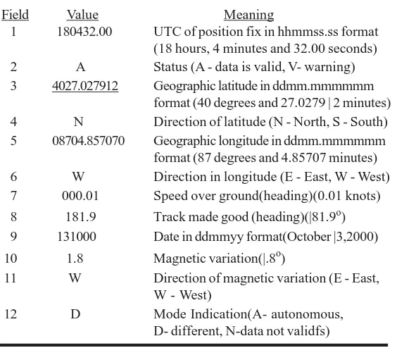
Table 1. $GPRMC Output Sentence Description
In this study two GSM modems (Cell-Phones) along with their SIM Cards where used. The first one serves as a transmitter of the processed GPS data from the MU to the control center, while the second one serves as a receiver in the control station for reception of GPS position coordinates of the MU, which is done via SMS text messaging protocol. Both cell-phones used are of the same type and features, in order to unify the interface programming steps and results for both parts of the GPS/GSM system, which are the mobile Unit (MU) and the Control Station Center. In order to extract information related to the position of a GPS receiver, it is necessary to record $GPRMC sentence that can be received on the receiver’s port [6]. This sentence indicates geographical longitude and latitude of position fix and corresponding UTC time (Universal Time Coordinate) [7]. The Table 1 defines the meaning of the fields in the $GPRMC output sentences. The underlined values are to be used in calculations. Both the latitude and longitude values included in a NMEA-0183 sentence are represented in degrees (d), minutes and decimal minutes (m). Latitude is formatted as ddmm.mmmm, while longitude is represented as dddmm.mmmm in a single field.
The direction of latitude and longitude are indicated as a single character in the next field (‘N’- north; ‘S ’- south; ‘E’ - east; ‘W ’ - west). Most computations that involve geographical coordinates require longitude and latitude to be expressed in decimal degrees with a corresponding sign (negative for south latitudes and west longitudes) [7 and 8].
3. Software Design
Start
Check GSM modem existence
Prompt GSM Failure and exit
Check GPS
receiver existence Prompt GPSFailure and exit
Initialize all Output Ports
Advanced and acquire input data and set tracking mode to manual : as default
Read GPS and GSM data End Program execution
Send SMS text message via GSM Telecommunications service
Send ready signal to GSM - modem
Acquire Control Station settings and phone number
Prepare Extracted GPS positon coordinates to be added to SMS Message
Close ports and exit
Automatically Process and display GPS data
Is tracking mode initialized?
Prepare Extracted GPS position Coordinates to be added to SMS
m e s s a g e
Is it switching to manual mode?
Is it switching to Automatic mode?
Process and display GPS data manually according to user
commands
3 2
Yes
Yes
Yes
Yes
Yes
No No
Yes No
No
No
should be implementable and satisfy the real time system requirements, the main advantage of this is to make system simpler and faster. The software was written by using Microsoft Visual Basic programming language (version 6.0)
The hardware parts of the GPS/GSM Based System practical model are interfaced and communicated with each other under the control of the software of the controlling program. It consists two parts; the first is the major program, which is responsible for controlling the Mobile Unit (MU), while the second one is responsible for managing the control station, each part has several sub-programs for controlling the specific devices used in building the system model.
The flowchart of the mobile unit program of the GPS/GSM Based System is shown in figure 2. To complete this program, there are two interfacing programs: program of interfacing the GPS receiver and reading GPS data and the program of interfacing the first GSM modem (Nokia 6670) - to- computer-A .
The flowchart of program interfacing the GPS receiver and reading GPS data is shown in figure 3. The $GPRMC frame gives the coordinate of the GPS receiver including longitude, latitude as well as time and date. While the flowchart of the first GSM modem (Nokia 6670) to computer interface program model is shown in figure 4.
Figure 3. Flowchart of the GPS receiver interface and data extraction program model. (2) represents the input data to MU program model
Start
Yes
No
2
Open selected GPS port
Initialize GPS Data reception
Acquire GPS receiver product description
Start retrieving GPRMC sentence
Extract Longitude, Latitude, Time and Date
Is tracking mode ON?
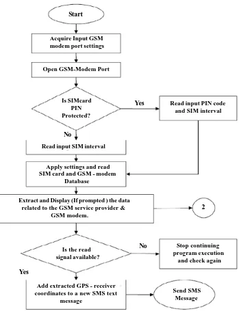
On the other hand, the program model of the control station is used to manage the interface between computer-B and the second Nokia GSM-modem. Its flowchart is shown in figure 5. It follows the same steps as in the flowchart of figure 4 by acquiring the GSM port settings, opening the port for data retrieval, checking for available PIN codes and the extraction of the GSM modem and service provider related data. Then it will extract the received text message stored in the GSM-modem inbox. After that it will process and display the GPS position coordinates of the mobile unit using any text message editor application available such as the Nokia text message application then the coordinates can be displayed graphically on the Garmin digital map source if required by the user.
4. Results of Measurements
The system test involves the execution of both part of the system, the mobile unit and the control station models using two types of GPS: ordinary GPS and differential GPS techniques as follows.
Start
Open GSM-Modem Port Acquire Input GSM modem port settings
Is SIMcard PIN Protected?
Is the read signal available?
2
Yes
No
Send SMS Message
Stop continuing program execution and check again Extract and Display (If prompted ) the data
related to the GSM service provider & GSM modem.
Apply settings and read SIM card and GSM - modem Database
Read input SIM interval
Add extracted GPS - receiver coordinates to a new SMS text
message
Read input PIN code and SIM interval
Figure 4. Flowchart of the GSM-modem interface program model
Yes
4.1 Using ordinary GPS
Three sites were selected to perform the measurements and the original position coordinates of three predefined places were acquired using Garmin and Google Digital- Maps. Those sites are :
1. Site-A: The building of the department of electronic and communications engineering for AL-Nahrain University. 2. Site-B: The building of the AL-Nahrain University Health Center.
3. Site-C: The tower of the University of Baghdad.
The coordinates of each site mentioned above obtained in this method were named A1, B1 and C1 respectively.
The position coordinates of the above sites were measured using the practical implemented system and repeated for three times at each of the specified sites. The points acquired in the practical system test were named A2, B2 and C2.
The detailed coordinates of the sites that were obtained in both methods (during the system test and using digital maps) can be
Start
No
Yes
Input GSM-Modem Port settings
Open GSM-Modem Port
Is SIM card PIN protected?
Read input PIN code
Apply settings and read SIM card Database
Extract and Display (If Prompted) the data related to the GSM - service provider and GSM - modem.
Read GSM - modem Inbox data
Display received text message data using Nokia text message editor application
Project the MU position coordinates on the Digital Map source application
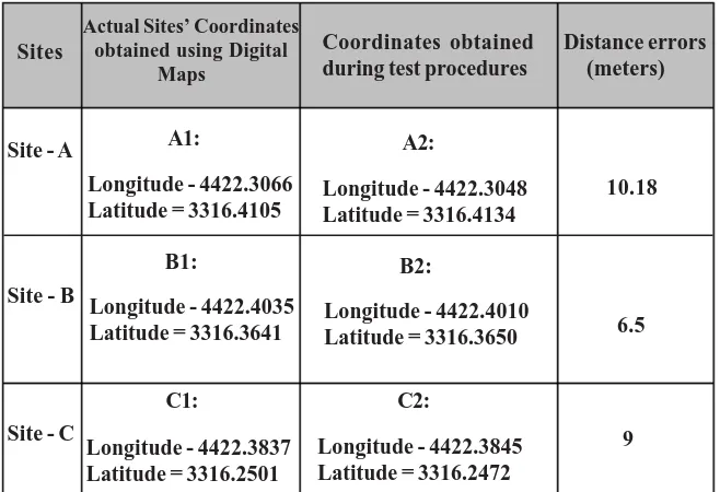
seen Table 2. It is indicated that an accuracy of less than 10m is obtained compared with the original coordinates taken from digital map and this value is in the accuracy range of the used ordinary GPS.
4.2 Using differential GPS
The concept of differential GPS technique has been applied on the implemented system when the received data (representing GPS reading at the mobile unit) by the control station is corrected according to the difference value obtained between GPS reading and the original coordinates of the control station[9]. For this purpose, seven experiments representing seven sites were achieved to examine the data transmission through the implemented system. The obtained errors in the horizontal (longitude and latitude) and the vertical (altitude) coordinates according to the original coordinates are recorded in Table 3.
Sites
Actual Sites’ Coordinates obtained using Digital Maps
Coordinates obtained during test procedures
Distance errors (meters)
Site - A A1:
Longitude - 4422.3066 Latitude = 3316.4105
Longitude - 4422.4035 Latitude = 3316.3641
B1: Site - B
Site - C
C1:
Longitude - 4422.3837 Latitude = 3316.2501
A2:
Longitude - 4422.3048 Latitude = 3316.4134
Longitude - 4422.4010 Latitude = 3316.3650
B2:
C2:
Longitude - 4422.3845 Latitude = 3316.2472
10.18
6.5
9
Table 2. The position Coordinates obtained in two methods Using ordinary GPS
Experiment No.
Horizontal error of coordinate (meters)
Vertical error of coordinate (meters)
1 0.25 0.25
2 0.35 0.38
6 0.24 0.24
3 0.35 0.24
5 0.46 0.30
Table 3. The coordinate errors using differential GPS
After the system has been tested experimentally, it is clear that a horizontal accuracy of 0.44m and a vertical accuracy of 0.55m are obtained (or the accuracy is less than 0.6m for both coordinates).
4 0.79 0.38
5. Conclusion
The present work has been carried out to design the hardware and develop the software of the GPS based on existing SMS service of GSM network in order to evaluate the implemented system experimentally. The proposed GPS/GSM based system model includes two parts which are the mobile unit and the control station. The system processes, interfaces, connections, data transmission and reception of data between the mobile unit and the control station has been performed and tested successfully and accuracies less than 9m and 0.6m are obtained compared with the original coordinates using ordinary GPS and differential GPS respectively. These results are compatible with the accuracies of used GPS technologies.
References
[1] Pacific Crest Corporation. (2000). The Guide to Wireless GPS Data Links , Second Edition, October.
[2] Chen , H., Chiang, Y., Chang, F., H. Wang, H. (2010). Toward Real-Time Precise Point Positioning:Differential GPS Based on IGS Ultra Rapid Product,SICE Annual Conference, The Grand Hotel, Taipei, Taiwan August 18-21.
[3] Kaplan, E. (1990). Understanding GPS: Principles and Applications , Norwood, MA: Artech House.
[4] El-Rabbany, A., Chrzanowski, A., Santos, M. (2001). GPS Applications in Civil Engineering, Ontario Land Surveyor Quarterly, Summer.
[5] Matthias Kracht. (2004). Tracking And Interviewing Individuals With Gps And Gsm Technology On Mobile Electronic Devices, Institute of Transport Research, Berlin, Germany.
[6] Matthias Kracht. (2004). Tracking And Interviewing Individuals With Gps And Gsm Technology On Mobile Electronic Devices, Institute of Transport Research, Berlin, Germany.
[7] Garmin International Corporation. (2006). Garmin NMEA sentence Technical Specifications, U.S.A, Official Site: www.garmin.com, April.
[8] Ralf Kretschmann. (2007). USB-Interface, MFTech, Deutschland.
[9] Asaad Al-Hindawi, Majeed Nader. (2012). Performance of Differential GPS Based on a Real-Time Algorithm Using SMS Services of GSM Network, IEEE International Conference on Future Communication Networks , ICFCN’2012, University of Nahrain , Jadriya, Baghdad, Iraq, April 10-12.
Author Biography
Dr. Asaad Al-Hindawi has earned his B.Sc. in electrical engineering from the University of Baghdad, Baghdad, Iraq. In addition, he has received M.Sc. in communication engineering from the University of Technology, Baghdad, Iraq and a Ph.D. in Radio and communication engineering, from Varna Technical University, Varna, Bulgaria. Currently he is an Assistant Professor of communication Engineering and Laboratories Advisor in Communication Engineering Department, Sulaimani Technical