Doctoral School in Civil, Environmental and
Mechanical Engineering
Topic 1. Civil and Env
ironmental En
gineering
2017 - Docto
ral thesis
Andrea Morbioli
Analysis and development of
nonlinear Finite Elements for
modelling steel structures at
Doctoral Thesis - June 2017
Andrea Morbioli
Analysis and development of nonlinear Finite Elements
for modelling steel structures at ambient
and elevated temperature
Supervisors
Dr. Nicola Tondini, University of Trento, Italy
Prof. Jean-Marc Battini, KTH - Royal Institute of
Except where otherwise noted, contents on this book are licensed under a Creative Common Attribution - Non Commercial - No Derivatives
4.0 International License
University of Trento
Doctoral School in Civil, Environmental and Mechanical Engineering
http://web.unitn.it/en/dricam
Via Mesiano 77, I-38123 Trento
Cycle: XXIX
Final Examination 29/06/2017
Board of Examiners:
Prof. Oreste Salvatore Bursi (University of Trento)
My deepest gratitude goes first and foremost to my supervisor Nicola Tondini for his constant encouragement and guidance. He has walked me through this experience assuring the maximum support and availability.
I would like to express my gratitude to Prof. Jean-Marc Battini, who helped me during my study at KTH (Royal Institute of Technology of Stockholm). He provided, without parsimony, his time, knowledges and suggestions to support me in the implementation of the thermomechanical finite element.
I also want to thank the University of Trento and the research group of Prof. Oreste S. Bursi for the Ph.D fellowship.
Summary: motivations and aims of the thesis work p.1
TOPIC 1: Numerical analysis of flexural capacity of cold formed steel profiles
subjected to monotonic bending moment
1. Introduction p.5
1.1 Relevance of experimental-numerical studies on cold formed steel profile: state
of the art p.5
2 Case study: experimental programme p.6
3 Numerical modelling of cold formed profiles p.10
3.1 Material characterization of the specimen: effect of cold forming process p.10 3.2 Evaluation of residual stresses, related impact in cold formed steel structural
behaviour and their inclusion into the numerical model p.13
3.3 Introduction of geometrical imperfections and their influence in the numerical
model p.14
3.4 Description of the numerical model p.16
4 Numerical outputs p.18
4.1 Parametric analyses p.21
References p.23
Enclosure: PAPER 1 Cross-sectional flexural capacity of cold-formed
laterally-restrained steel rectangular hollow flange beams. pp.25-54
TOPIC 2: Coupling methodologies between a CFD and an FE software for the analysis
of structures at high temperatures.
1 Introduction p.55
2 CFD and FE software p.56
2.1 Fire Dynamics Simulator (Mc Grattan et al., NIST) p.57
4. Weak coupling CFD-FE approach: practical description of the procedure p.60 5 Behaviour of real steel-concrete open car park subjected to localized fires p.63
6. Case study: a steel-concrete open car park, CFD-FE weak coupling p.65
References p.71
Enclosure: PAPER 2 An integrated modelling strategy between a CFD and an FE
software: methodology and application. pp. 73-96
TOPIC 3: Development of a co-rotational beam element for the study of steel structures
subjected to fire loadings.
1 Introduction p.97
2 Co-rotational beam element p.98
3 Finite element model implementation of co-rotational beam theory p.100
4 Thermomechanical behavior of carbon steel at high temperature p.103
5 Integration of material constitutive law p.106
6 Optimization of convergence procedure based on different displacement
predictor p.111
7 Path following techniques, branch-switching procedure applied to instability
problems of steel structures subjected to fire p.112
References p.115
Enclosure: PAPER 3 A co-rotational two dimensional beam element for the analysis
of elastic-plastic instability of steel structures subjected to fire. pp.117-160
Conclusions p.161
Topic 1:
Fig. 1 Cold formed profiles for structural applications; a) Building frame realized with
cold formed profiles, b) Z cold formed elements used as purlins elements in roof system p.6
Fig. 2 Geometry of the cross-section; a) RHFB 300, b) RHFB 240 p.7
Fig. 3 Lateral and side view of the experimental set-up p.8
Fig. 4 Instrumentation set-up of RHFB beams; a) RHFB 300, b) RHFB 240 p.9
Fig. 5 Experimental test; a) Side view of the set up, b) Detail of web stiffener with end
plate support p.9
Fig.6 Example of a tensile test stress-strain relationship; a) RHFB 300 material data for
tube flat and tube corner zone, b) RHFB 240 material data for tube flat and tube corner
zone p.11
Fig.7 Von Mises criterion; a) Von Mises yield surface in principal stress space ,b)
Isotropic hardening (with reference to a uniaxial tensile test for the Von Mises yield
surface in the deviatoric plane p.12
Fig.8 Beam tested specimens; a) View of the specimen cross section, b) Bending caused
by flexural residual stresses released after coupon extraction p.14
Fig.9 Buckling shape referred to the lowest eigenmode p.15
Fig.10 Introduction of geometry imperfections in the 3D model p.16
Fig.11 Finite element model of the beam, RHFB 240 specimen p.17
Fig.12 Shell 181 Ansys element p.17
Fig.13 Detail of mesh discretization, local refinement, and end support constraint p.18
Fig.14 Bending moment – displacement curves; a) RHFB 300, b) RHFB 240 p.19
Fig.15 Plastic mechanism for the superior compressed flange, first evidence; a)
Experimental test, b) Numerical output p.20
Fig.16 Plastic mechanism for the superior compressed flange, second evidence; a)
Experimental test, b) Numerical output p.20
Fig.17 Web buckling RHFB300; a) Experimental test, b) Numerical output p.21
Fig.18 Plasticization on the superior flange for RHFB240 profiles; a) Experimental test,
b) Numerical output p.21
Fig.19 Parametric analysis a) RHFB300 b) RHFB240 p.23
Topic 2:
Fig.1 Full coupling approach between the three steps involved in the fire analysis p.58 Fig.2 Weak coupling approach between the three steps involved in the fire
analysis p.60
Fig.3 Integration of the radiant intensities necessary to compute the impinging flux on
structural elements; a) Radiant intensities incoming on a hemisphere (The number of radiant intensities is purely representative), b) Necessity of a spherical interpolation due
to different surfaces orientation p.61
Fig.4 Determination of the angle of visibility for an IPE profile p.63
Fig.5 Experimental fire test on a real scale steel-concrete composite car park realized
in France; a) View of the overall geometry, b) Plan view p.63
displacement, b) Vertical displacement of selected beam points p.65
Fig.8 Analysed fire scenario; a) Position of cars for the reference fire scenario involving
three cars, b) Rate of heat release as a function of time by three cars in the reference
fire scenario p.66
Fig.9 Numerical modelling; a) FE element model of the car park in SAFIR, b) FDS
model of the compartment without the inclusion of superior beams c) FDS model of
the compartment with the inclusion of superior beams. p.67
Fig.10 Cross section temperature distribution under a localized fire Hasemi model,
measured at collapse (27 min.); a) HEB220 column steel profile b) IPE400 secondary
beam steel profile p.68
Fig.11 Structural numerical response of the structure under a Hasemi localized fire
model; a) Position of structural points in which the displacement is detected b) Vertical
displacements of reference points (top column and secondary beam midspan) p.68
Fig.12 Cross section temperature distribution measured at collapse (27 min.); a)
HEB220 column steel profile, b) IPE400 secondary beam steel profile p.69
Fig.13 Structural numerical response of the structure under CFD-FE weak coupling
approach; a) Position of structural point in which the displacement is detected, b)
Vertical displacement of reference point by assuming the FDS model with or without
superior beams and comparison with correspondent Hasemi model p.70
Topic 3:
Fig.1 Beam Kinematic p.100
Fig.2 Steel properties under the effect of temperature as predicted by models and
experimental tests;
a) Thermal conductivity, b) Specific heat p.103
Fig.3 Steel properties under the effect of temperature as predicted by models and
experimental tests;
a) Yield strength, b) Elastic modulus p.104
Fig.4 Eurocode 3 stress-strain constitutive law for carbon steel at high
temperature p.105
Fig.5 Thermal strain: comparison between available models and experimental data
outcomes p.106
Fig. 6 Integration of material uniaxial constitutive law at high temperature p.108
Fig. 7 Finite element validation against experimental test: steel portal frame subjected
to an ISO 834 fire curve; a) Geometry and data of the case study, b) Comparison of
displacements as function of element temperature p.109
Fig. 8 Example of finite element validation against numerical predictions of SAFIR
software; a) Geometry and data of the case study, b) Comparison between the two
models on the vertical displacement of loaded node p.110
Fig. 9 Scheme of the proposed displacement predictor p.111
Fig. 10 Difference between the finite element model of a compressed column to be
introduced in a commercial finite element code and via branch-switching
Topic 1:
Table 1 Nominal section dimensions of the specimens. Dimensions in mm p.7
Table 2 Measured section dimensions of the specimens. Dimensions in mm p.7
Table 3 Flexural behaviour comparison between numerical and experimental
results p.18
Topic 2: Not present
Topic 3:
Table 1 Solution scheme, co-rotational finite element p.102
Table 2 Modifications introduced in the solution scheme by branch-switching
1
Summary:
2 This thesis work aims to successively analyze and develop "ex novo" problems concerning the use of finite elements for the analysis of issues characterized by high plasticity, geometrical and material nonlinearity, large displacements and rotations; all
combined with the effect of temperature on the material mechanical properties. The ultimate objective of the work is the analysis and development of nonlinear Finite Elements devoted to the modelling of steel structures at ambient and elevated temperature.
Three different experiences will be analyzed in this elaborate; each of them
characterised by specific issues that may be involved in the analysis via finite element method of steel structures at ambient and elevated temperature. At the same time innovative aspects that are related, for example, to the particular typology of the analyzed case study (first case) or in the methodology used in the treatment of the problem (second and third case) are investigated. The thesis structure chronologically retraces this path and the results and the experience gained from each of them were exploited to ultimately implement a thermomechanical finite element that is expression of all the tackled problems. The thesis consists of a collection of three papers that have been published or submitted on each of the investigated topics.
In detail:
- In the first paper, a commercial finite-element code, of the type "multipurpose", such as ANSYS has been used for the analysis of innovative cold-formed, laterally-restrained steel rectangular hollow flange beams subjected to monotonic bending test. The numerical analysis has been carried out by means of the direct comparison with
experimental tests on real scale specimens; that has allowed the detection of some
phenomenological problems that have been included in the model calibration. From a numerical point of view, this work has at first allowed to deeply investigate the plastic problem by means, for example, the appropriate identification of the constitutive laws for the material, the correct choice of hardening law and yield surface, and their impact on the model. The local buckling problem typical of these profiles has been evaluated, through the use of shell elements. Furthermore, the effect of the global and local imperfections, which have been introduced in the model with different amplitudes, has been deeply investigated by evaluating their effect on the ultimate load. The calibration of the model finally allowed to perform a series of parametric analyses in order to extend the results to an extended range of profiles, characterized by different slenderness.
3 nonlinearity and large displacements on the structure in addition to the temperature effect on materials mechanical properties. The case study has been used to evaluate the assumptions and the issues that arise when developing an innovative integrated modelling methodology between a computational fluid dynamics (CFD) software applied to compartment fires and a finite element (FE) software applied to structural systems. Particular emphasis has been given to the weak coupling approach developed between the CFD code fire dynamics simulator (FDS) and the FE software SAFIR.
5
TOPIC 1:
Numerical analysis of cold formed steel profiles subjected to
monotonic bending moment
1 Introduction
This section focuses on the development of a numerical work aimed at predicting the section bending moment capacity of cold-formed steel rectangular hollow flange beams (RHFBs). The geometry of RHFB comprises two torsionally stiff rectangular tube flanges connected by a slender web through welding. The numerical model is based on the results obtained from an experimental test programme reported in [1].
The following paragraphs describe the issues and assumptions that were considered to numerically capture the behavior of these specimens by introducing the fundamental phenomena that are involved in the modeling process of thin-walled steel beams. The focus is the achievement of a calibrated finite element numerical model, able to predict the behavior of RHFB beams also characterized by different slenderness or plate thickness compared to those tested during the experimental campaign.
This is therefore recommended to preliminarily evaluate the effective resistance, under the particular load configuration, of such beams and consequently assess their convenience in term of performance and costs.
1.1 Relevance of experimental-numerical studies on cold formed steel profile: state of the art
6
(a) (b)
Fig. 1 Cold formed profiles for structural applications; a) Building frame
realized with cold formed profiles [6], b) Z cold formed elements used as purlins elements in roof system [7]
Moreover, thin walled cold formed profiles subjected to flexure may be sensitive to local, distortional and lateral torsional buckling that can reduce the bending capacities below the elastic moment My. This prevents the possibility to develop the inelastic
reserve of the cross section. As a consequence sudden failure mechanisms may be observed even though the material has not even reached the elastic limit.
Several experimental tests were performed in last years by researchers in order to analyse these issues. Test results are compared with the outcomes deriving from finite element models that are used to numerically simulate the real physical behaviour. On these premises, the present work aims to investigate the performance of a new I-shape cold formed profile, realized by means of two rectangular hollow flange cross sections connected by a slender web. A numerical model was then calibrated on the basis of the experimental evidences. The study analyses in particular the inelastic flexural behaviour of cold formed beams by avoiding lateral or torsional buckling. The tested beams were in fact conceived for the use as secondary beam elements in roof systems or slab of small steel-framed buildings where lateral displacements are generally prevented by the steel sheeting.
2 Case study: experimental programme
7
(a) (b)
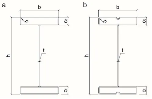
Fig. 2 Geometry of the cross-section; a) RHFB 300, b) RHFB 240.
The specimens were provided by Gruppo Manni an Italian steelwork company. Steel profiles were built by welding two structural tubes - produced by cold rolling - to a cut flat plate that constitutes the web. This fact prevented to introduce an intermediate stiffener on the outermost flat elements that are part of the tubes. This sort of detailing would be beneficial in order to reduce local buckling and crushing due to local effects of the flange in compression. Moreover, the way of producing the specimens was cause of higher imperfections with respect to those presumably expected if an appropriate cut machine had been used.
Table 1 Nominal section dimensions of the specimens. Dimensions in mm.
hnom bnom ct.nom tnom L
RHFB-240 240 100 20 2.0 4500
RHFB-300 300 150 30 3.0 4500
Table 2 Measured section dimensions of the specimens. Dimensions in mm.
h b ct t ri L
T01 RHFB-240 235.2 100.0 19.8 1.92 1.75 4495
T02 RHFB-240 235.6 99.4 19.8 2.01 1.75 4495
T03 RHFB-240 235.6 100.0 20.0 2.00 2.25 4495
T04 RHFB-240 235.3 99.9 19.7 2.01 2.50 4495
T05 RHFB-300 298.3 150.0 30.4 2.87 3.00 4498
T06 RHFB-300 296.8 150.1 30.0 2.86 3.50 4496
T07 RHFB-300 297.5 150.1 30.2 2.93 3.50 4498
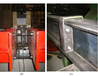
8 in contact with the specimen. Moreover, transverse stiffeners were welded at supports and at load points to avoid either web buckling or web crushing or web crippling owing to concentrated transverse loads, as depicted in Fig. 3.
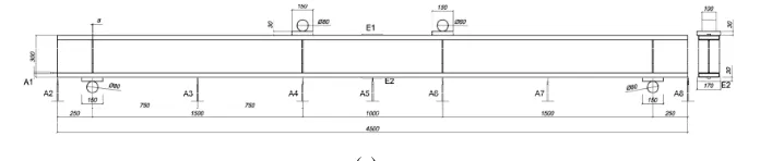
Fig. 3 Lateral and side view of the experimental set-up
As previously mentioned, the load was applied by means of a four-point bending scheme in order to induce in the central span, i.e. the length between the two load application points, constant bending moment and zero shear force. In this way, the midspan load condition of a simply supported beam could be well reproduced. The load was introduced by means of a hydraulic actuator that was displacement-controlled at a speed of 0.5 mm/min.
The total length of the specimens and the distance between the two point loads were selected on the basis of the recommendations provided in Appendix A.3.4 of EN1993-1-3 (2006). As a result, the total length was 4.5 m, the span between supports 4 m and the distance between point loads 1 m. The end supports consisted of a hinge and a roller, respectively.
9
(a)
(b)
Fig. 4 Instrumentation set-up of RHFB beams; a) RHFB 300, b) RHFB 240
(a) (b)
10
3 Numerical modelling of cold formed profiles
In next paragraphs the main issues and assumptions that were involved in the study of cold formed profiles will be introduced and analysed. The aim is to develop a numerical model able to predict experimental outcomes and consequently take into account the main physical phenomena that are involved in the examination of flexural resistance of rectangular hollow flange beams. The numerical calibrated finite element model could then be used in order to perform parametric analyses.
Numerical studies on cold formed profiles are already available in literature. Anapayan and Mahendran [2] analysed for example the lateral buckling behaviour of C shape hollow flange beams, Shifferaw and Schafer [3] introduced numerical models for predicting the inelastic bending capacity of back to back C or Z sections subjected to 4 point bending tests; Avery et al. [8] numerically studied the flexural capacity of hollow triangular flange beam developed and designed in Australia for use as a flexural member. Other studies could be reported for different profiles shape or load conditions [9, 10], however not redundant analyses are until now available for similar designed rectangular hollow flange beams. This work aimed to expand the knowledge of flexural resistance also to this innovative cold formed steel profile.
3.1 Material characterization of the specimen: effect of cold forming process
Carbon steel presents a stress-strain curve that is usually characterized by a linear elastic range followed by a yield plateau. In many cases the material is modelled by means of a bi-linear curve.
Other metals, such titanium, aluminium and stainless steel have nonlinear stress-strain curves featuring relative low proportionality stresses and extensive strain-hardening ranges [11]. In these cases a particular criterion for defining the yield limit must be specified. For stainless steel, for example, the equivalent yield stress is determined on the base of the permanent strain of the 0.2% proof stress.
Moreover in the case of cold formed profiles, realized with carbon steel or stainless steel, the working process due to cold rolling modifies the classical stress-strain relation by introducing a significant strength enhancements in the corner regions due to hardening. Indeed for flat regions in particular near corners area the elastic-plastic transition is smoother.
The definition of the representative stress-strain curve, also with reference to the specific position of the material in the cross section, is therefore of particular importance to define with a sufficient order of accuracy the structural behaviour in particular when buckling phenomena are involved.
11 to correctly capture the generation of local buckling effects in the compressed elements of the specimen. A campaign of tensile tests on different material specimens were then carried out in order to obtain sufficient data to successively numerically reproduce the experimental evidences. The study involved 25 specimens extracted from different region of the flange tubes (corner, lateral border and superior flat zone) and web. The obtained stress-strain relations are then reported in Fig.6.
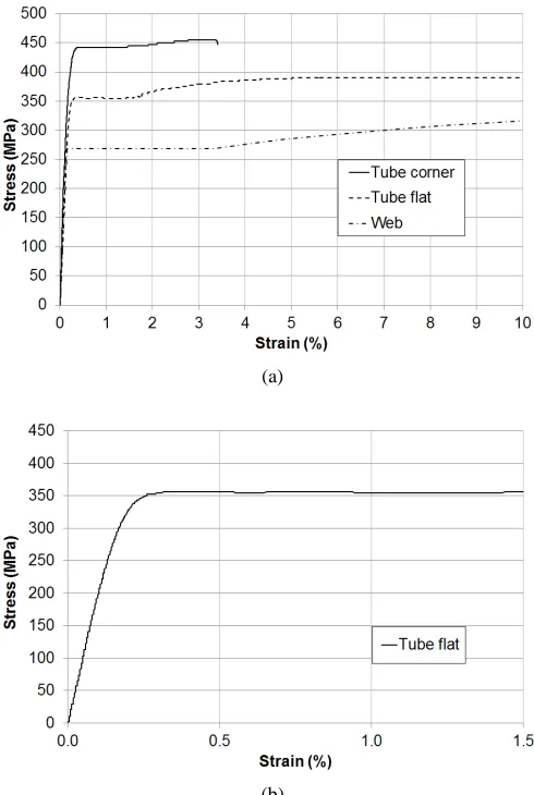
(a) (b)
Fig.6 Example of a tensile test stress-strain relationship; a) RHFB 300 material data for tube
flat and tube corner zone, b) RHFB 240 material data for tube flat and tube corner zone
The tensile tests revealed that a significant increase in yield strength, due to cold forming process, was actually observed in the corner zone respect to the flat part of the tube flange. The percentage of increase, obtained from an average measure performed on all tested specimens, was around +28% for RHFB 240 beams and +30% for RHFB 300 profiles.
The results of the investigation on material characterization were then employed in the numerical finite element model.
True stress – strain relationships were employed for material properties because more representative of the state of material in large strain analyses.
(
1)
t e e
σ =σ +ε (1)
(
)
ln 1
t e
ε = +ε (2)
The Poisson’s ratio was taken equal to 0.30. The Multilinear Isotropic Hardening (MISO) material law, available in ANSYS [15], was instead used for implementing the true stress – strain data. It allows including a user-defined stress-strain relationship by means of several linear segments. The material model relies on the Von Mises criterion, a classical yield criteria introduced in 1913 based on the second deviatoric stress invariant J2. The physical idea of the criterion is that: “the plastic yielding begins when the J2 stress deviator invariant reaches a critical value”. The critical value mainly
0 2 4 6 8 10 0 100 200 300 400 500 600 Strain (%) S tr e s s ( M P a )
Tube flat RHFB-240 Tube corner RHFB-240
0 2 4 6 8 10
0 100 200 300 400 500 600 Strain (%) S tr e s s ( M P a )
12 depends on a hardening internal variable that is intrinsically connected with the density of dislocations in the crystallographic microstructure that causes an isotropic increase in resistance to plastic flow [16]. In some cases (i.e. isotropic hardening), the internal variable could be easily expressed by means of a singular scalar value whose amplitude determines the size of the yield surface. In the case of the Von Mises criterion the yield surface could be defined as:
3 2
fσ = J −σ y (3)
where σy is the uniaxial yield stress.
In the space of principal stresses the yield surface associated with the Von Mises
criterion is represented by the surface of an infinite cylinder (see Fig.7a); whose axis
coincides with the hydrostatic axis. In the biaxial stress space it is an ellipse symmetric with respect to the origin of the principal stress plane (Fig.7b).
(a)
(b)
Fig.7 Von Mises criterion; a) Von Mises yield surface in principal stress space, b) Isotropic
13 It is important to note that the pressure component of the stress tensor is not included in the definition on the Von Mises criterion, as a consequence the yielding is influenced only by 2J .
For that reason the criterion could be used to describe the elastic-plastic behavior of material in which the failure is due to slip between dislocation planes (ductile metals), however is not suitable for describing concrete-based material, for which the effect of hydrostatic component should be taken into account.
In the MISO model, based on isotropic hardening, the yield function exhibits a uniform
expansion of the initial yield surface without translation; this choice was deemed adequate for the purpose because of the monotonic nature of the experimental tests.
3.2 Evaluation of residual stresses, related impact in cold formed steel structural behaviour and their inclusion into the numerical model
Cold formed profiles undergoes forming and fabrication processes that could produce high values of residual stresses with a consequent impact on the structural behaviour of steel elements. Residual stresses are caused by plastic deformation or temperature gradients induced in the metal and due to rolling, welding, grinding, heat treating etc. In relation with their magnitude and position they could produce negative effects on fracture, fatigue, brittle fracture and buckling phenomena [17]. The knowledge of residual stresses, and their introduction in the numerical model, is necessary in order to correctly model the flexural behaviour of the beams and to take into account the buckling phenomena that could affect the compressed parts.
14
(a) (b)
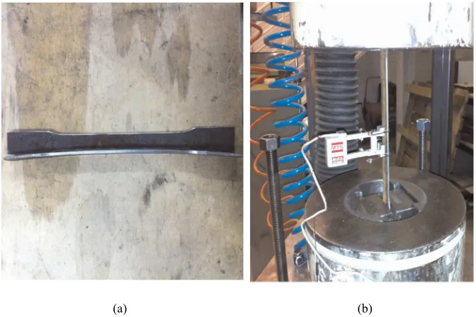
Fig.8 Beam tested specimens; a) View of the specimen cross section, b) Bending caused by
flexural residual stresses released after coupon extraction
The stress-strain relationship obtained from tensile tests includes flexural residual stresses whose magnitude is not negligible for cold-formed sections [19]. The proof of residual stresses presence was also observed after coupon extraction by observing the bending of material specimens due to the release of flexural residual stresses (Fig. 8b). Conversely, membrane residual stresses were not measured because small with respect to flexural residual stresses, apart from corner regions. These zones are also affected by the increase in yield stress due to cold forming work process.
The cold working enhancement was not included in the corner zones because the membrane residual stresses were not modelled: in fact, they tend to counteract one another.
On the other hand if the increase in yield strength has been included in the model, residual stresses have to be explicitly introduced. The followed methodology applied to the specific case study has effectively demonstrated a dependence of the ultimate bending moment Mu on residual stresses. Generally the introduction of residual
stresses, both flexural and membrane, reduces the value of Mu by causing premature
buckling phenomena of the compressed part.
3.3 Introduction of geometrical imperfections and their influence in the numerical model
15 nominal values reported in Table 2) and the real configuration of the profile. Their introduction was indeed of fundamental importance in particular for this case study, where a high level of imperfections were observed on all tested beams. As previously mentioned the presence of high imperfections on specimens was mainly connected to the working process employed for their fabrication and the absence of a specific cut machine.
Two problems should be take into account when a geometrical imperfection has to be introduced into a numerical model. The first relies on the determination of the imperfection shape, the second regards the correspondence amplitude. With reference to the second point, the present study follows the methodology introduced by Schafer and Pekoz [19] that quantify the maximum amplitude imperfection d as a function of the element width w:
0.006
d = w (4)
The shape of the imperfection was instead determined by means of a linear buckling analysis referred to the eigenvector associated to the lowest eigenvalue Fig.9.
Fig.9 Buckling shape referred to the lowest eigenmode
16
Fig.10 Introduction of geometry imperfections in the 3D model
Different value of amplitude were tested; finally the maximum value proposed by
Schafer and Pekoz [19] was maintained in order to calibrate experimental data. Performed finite element simulations demonstrates a direct connection between the imperfection amplitude and the ultimate bending moment Mu (an increment of
amplitude progressively reduces the value of Mu and vice versa).The introduction of
geometrical imperfections also modify the failure mechanism that instead would be observed in the presence of an ideal structure.
3.4 Description of the numerical model
Numerical nonlinear models provide a comprehensive means to investigate cross-section slenderness, plastic material reserve, activation of local buckling phenomena and other effects that influence the bending strength of beams.
17
Fig.11 Finite element model of the beam. RHFB 240
More in detail, the SHELL 181 element (Fig.12), available in the ANSYS elements library [15], was used in order to model all the part of the beam. The element is suitable for analyzing thin to moderately-thick shell structures. It is a four-node element with six degrees of freedom at each node: translations in the x, y, and z directions, and rotations about the x, y, and z-axes [15]. SHELL 181 includes the linear effects of transverse shear deformation.
Fig.12 Shell 181, Ansys element [15]
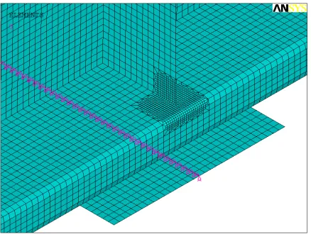
A mesh sensitivity investigation was initially performed in order to introduce an adequate model refinement able to accurately predict the spread of plasticity and arise of local buckling effects. Finally a uniform mesh, constituted by means of square shape elements, 5mm wide, was introduced for all the simulations. All the parts of the beam, included the intermediate web stiffeners and the end plates supports, were modelled into ANSYS. Restraints were applied, accordingly to the static scheme, to the end plates along an ideal line (Fig. 13) in order to distribute the reaction forces.
18 constraint equations CERIG command [15]. Load was applied by introducing an increasing displacement ramp to all nodes belonging to the intermediate web stiffeners, located at half meter from the midspan. Lateral constraints were then introduced in order to prevent the lateral torsional buckling and simulate the constraint effect of the lateral HE300B profiles.
Fig.13 Detail of mesh discretization, local refinement, and end support constraint
4 Numerical outputs
The accuracy of the final element model was checked by comparing the ultimate moment capacity Mu and the vertical displacement δu at midspan in correspondence of
Mu.
Results are reported in Table 3.
Table 3 Flexural behaviour comparison between numerical and experimental
results.
/
, ,
Mu FE Mu TEST δu FE, /δu TEST,
T01 RHFB-240 1.02 0.90
T02 RHFB-240 1.05 0.93
T03 RHFB-240 1.04 0.93
T04 RHFB-300 1.03 0.98
T05 RHFB-300 0.98 0.81
T06 RHFB-300 1.04 0.95
Average 1.03 0.92
COV 0.02 0.06
The finite element model generally tends to overestimate the ultimate moment capacity Mu of the tested beams that demonstrate to be more deformable (mainly for the effect
19 the ultimate moment capacity of the profiles.
The bending-moment displacement curves for two specimens (T01 RHFB 240) and (T04 RHFB 300) are showed in Fig. 14. In the figures the results of the numerical simulation are superimposed to the experimental evidences.
(a)
(b)
Fig.14 Bending moment – displacement curves; a) RHFB 300, b) RHFB 240
The validation of the numerical model takes into account also the comparison of the failure mode that was observed experimentally with the equivalent mechanism detected by means of the finite element simulation.
The plastic mechanism that involved the top compression flange of the tested specimen
0 5 10 15 20 25 30 35 40 45
0 20 40 60 80 100 120 Displacement (mm) M o m e n t (k N m )
T04 RHFB 300 - NUMERICAL T04 RHFB 300 - TEST
0 5 10 15 20 25 30 35 40 45
0 5 10 15 20 25 30 35 40 45 Displacement (mm) M o m e n t (k N m )
20 is depicted in Fig. 15a and Fig. 16a, while Fig. 15b and Fig.16b show the correspondence numerical output. The finite element model demonstrates to well capture the arise of buckling phenomena that affects the superior flange. The web buckling observed for RHFB 300 specimens was also well represented in the numerical model Fig. 17. The finite element model of the RHFB 240 specimens was although not able to detect some minor plasticisation occurred early in the tests as depicted in Fig. 18. These profiles (RHFB 240 series) were in fact more affected by imperfections and local effects that increase their deformability with a deviation in the elastic branch as illustrated in Fig. 14b.
(a) (b)
Fig.15 Plastic mechanism for the superior compressed flange, first evidence; a) Experimental
test, b) Numerical output
(a) (b)
Fig.16 Plastic mechanism for the superior compressed flange, second evidence; a)
21
(a) (b)
Fig.17 Web buckling RHFB300; a) Experimental test, b) Numerical output
(a) (b)
Fig.18 Plasticization on the superior flange for RHFB240 profiles; a) Experimental test, b)
Numerical output
4.1 Parametric analyses
A series of parametric studies were performed in order to expand the available findings to a wider range of beam slenderness.
22 The dimensions of the cross section were the ones of the T01 RHFB-240 profile and the T04 RHFB-300 profile but the thickness that was varied between 1.2 mm and 4 mm for the RHFB-240 profile and between 1.8 mm and 5 mm for the RHFB-300 cross section, respectively. The limit of a Class 3 section according to the EN1993-1-1 [20] was assessed by plotting the normalised ultimate moment Mu over the elastic bending
moment My with respect to the most limiting c/tε slenderness value that was the tube
flange in compression, where c is the flat width of the plate element, t its thickness and
ε = √(235/fy). As expected, the parametric study showed no considerable difference
between the two cross sections owing to geometry similarity normalised with respect to the material strength. In fact, from Fig. 14a and Fig 14b it is possible to observe that trend line obtained through linear regression has same slope and intercept values. From the same Figures it is possible to note that EN1993 tends to be conservative by underestimating the flexural capacity of RHFB cross-sections. The Class 3 limit is also conservative: from the parametric analyses the onset of local buckling of the tube flange in compression, i.e. when Mu/My < 1, is observed for c/tε equal to about 48 instead of
42. Furthermore, the capability of the DSM [21] of predicting the flexural behaviour of RHFBs was investigated. The main idea behind this method is the determination of all elastic instabilities, i.e. local Mcrℓ, distortional Mcrd, global buckling Mcre and the
bending moment that causes yield, i.e. My. The smallest moment among Mcrℓ, Mcrd, Mcre
and My identifies the bending resistance of the section. Since lateral-torsional buckling
and lateral-distortional buckling do not apply to the case study, only local buckling is considered. It is worth to point out that for comparison purposes input data of finite strip analyses in terms of geometry of the cross section and mechanical properties, i.e. yield strength, elastic modulus and Poisson’s coefficient, were chosen consistently with the FE analyses. The stress distribution was assumed according to the My.f. No
23
(a)
(b)
Fig.19 Parametric analysis a) RHFB300 b) RHFB240
References
[1] Tondini N., Morbioli A., Cross-sectional flexural capacity of cold-formed
laterally-restrained steel rectangular hollow flange beams, Thin-Walled Structures
(2015); 95: 196-207.
[2] Anapayan T., Mahendran M., Numerical modelling and design o LiteSteel
Beams subject to lateral buckling,Thin-Walled Struct. 50(2012):128–140.
[3] Shifferaw Y., Schafer B.W., Inelastic Bending Capacity of Cold-Formed Steel
Members, Journal of Structural Engineering (2012), 138(4):468-480.
40 50 60 70 80 90
0.4 0.6 0.8 1 1.2 1.4 c/tε M u /M y En1993 Prediction DSM Prediction Parametric Test
EN1993 Class 3 Limit
40 50 60 70 80 90 100
0.4 0.5 0.6 0.7 0.8 0.9 1 1.1 1.2 1.3 1.4 c/tε M u /M y En1993 Prediction DSM Prediction Parametric Test
24 [4] Ono T., Suzuki T., Inelastic behaviour and earthquake-resistance design
method for thin-walled metal structures, Proceedings of the IABSE Coll. on
Thin-Walled metal structures in Building (1986), Stockholm, 115-122.
[5] Della Corte G., Fiorino L., Landolfo R., Seismic behaviour of sheathed cold
formed structures: Numerical study, J. Struct. Eng. (2006), 132(4): 558-569
[6] https://sfia.memberclicks.net/how-cold-formed-steel-is-made
[7]
http://www.steel-rollformingmachine.com/china-cold_formed_steel_profile_cz_purlin_roll_forming_machine_ce_standard_380v_15k w-9297116.html
[8] Avery P., Mahendran M., Nasir A., Flexural capacity of hollow flange beams,
Journal of Constructional Steel Research (2000), 53: 201-223.
[9] Xu L., Sultana P., Zhou X., Flexural strength of cold-formed steel built-up box
sections, Thin-Walled Structures (2009); 47: 807-815.
[10] Keerthan P., Hughes D., Mahendran M., Experimental studies of hollow flange
channel beams subject to combined bending and shear actions, Thin-Walled Structures
(2014), 77: 129-140.
[11] Rasmussen K. J. R., Coupled instabilities in thin-walled metal structures, Notes for Phd Postgraduate course, 2014
[12] Engesser F., Zeitschrift fur Architektur und Ingenieurwesen, 1889. 35: p. 455.
[13] Engesser F., Schweizerische Bauzeitung 1895; 26: p. 24.
[14] Shanley F., Inelastic Column Theory. Journal of the Aeronautical Sciences
(1947); 14(5): 261-267.
[15] ANSYS, Documentation for ANSYS-release 14.0, Copyright SAS IP, Inc.,
2011.
[16] De Souza Neto EA, Peric D., Owen DRJ, Computational Methods for
plasticity, Theory and applications, Wiley 2008
[17] Rondal J., Peculiar Problems in Cold-formed Steel Design Part 1 and Part 2,
Light gauge metal structures recent advances, Cism Courses and Lectures
no.455-(2005), Springer.
[18] Rondal J., Residual Stresses in Cold rolled Profiles, Construction and Building Materials (1987); 1(3): 150-164
[19] Schafer B.W., Peköz T., Computational modelling of cold-formed steel:
characterizing geometric imperfections and residual stresses, J.Construct.Steel Res.
(1998); 47: 193–210.
[20] European Committee for Standardisation, Eurocode 3 Design of steel
structures - Part 1-1. General rules and rules for buildings
[21] Schafer B.W, Review: the direct strength method of cold-formed steel member
design,
25
PAPER 1: Cross-sectional flexural capacity of cold-formed
laterally-restrained steel rectangular hollow flange beams
The following paper was published in: Thin-Walled Structures (ELSEVIER)
“Cross-sectional flexural capacity of cold-formed laterally-restrained steel rectangular hollow flange beams” Vol. 95 pp.196–207 (2015)
27
Cross-sectional flexural capacity of cold-formed
laterally-restrained steel rectangular hollow flange beams
Nicola Tondinia and Andrea Morbiolia
aDepartment of Civil, Environmental and Mechanical Engineering, University of
Trento, Via Mesiano 77, 38123, Italy
Corresponding author: *[email protected]; ph: +39 0461 281976
Keywords: cold-formed steel profiles; rectangular hollow flange beams; flexural
capacity; experimental tests; numerical modelling.
Abstract
This paper presents the results of a comprehensive experimental-numerical study aimed at determining the flexural performance of cold-formed laterally-restrained steel rectangular hollow flange beams (RHFBs). Two RHFBs of different dimensions were considered as representative of typical secondary beams in small steel-framed houses. Results of the experimental study that consisted of i) material characterisation and ii) tests on full-scale specimens are thoroughly presented. Moreover, a numerical work was performed in order to develop a model able to reproduce the experimental outcomes and used to expand the available findings over a wider slenderness range through parametric studies.
1 INTRODUCTION
28 located away from the strong section axis. Moreover, hollow flange sections also provide torsional stiffness. Thus, RHFBs can be a potential alternative to C- and Z-sections as well as to small hot-rolled Z-sections thanks to: i) enhanced flexural behaviour associated with reduced weight; ii) ease of producing doubly symmetric geometry and iii) fast production times. Related research works were mainly devoted to the analysis of rectangular hollow flanges of channel sections [6-10] and to triangular hollow flanges of doubly symmetric I sections [11-13]. Numerical studies on symmetric rectangular hollow flange sections have been recently performed [14-18]. However, there is a lack of experimental testing on such profiles. On these premises, an experimental test programme on cold-formed steel RHFBs was planned in order to investigate their flexural performance by determining the section bending moment capacity. Furthermore, the experimental part is enriched by a numerical study with the following objectives: i) to calibrate a finite element model capable of reproducing the experimental evidences; ii) to perform a parametric analysis with the aim to broaden the results in terms of bending capacity to a wider range of slenderness ratios of the tube flanges; iii) to assess whether the prediction of the Eurocode EN1993 is adequate for such a cross section; iv) to evaluate how the Direct Strength Method (DSM) [2] estimates the flexural behaviour of RHFB cross sections.
The paper is articulated as follows: Section 2 describes in detail the experimental programme and the geometry of the specimens; Section 3 provides insight into the characterisation of the material properties; Section 4 presents and discusses the outcomes of the tests on the full-scale specimens; Section 5 introduces the numerical modelling and analyses the results of the model calibration; Section 6 describes the parametric studies, whereas Section 7 draws the conclusions and future perspectives.
2 EXPERIMENTAL PROGRAMME
The whole experimental programme was performed at the Laboratory of Structures and Materials Testing of the University of Trento. In detail, it was characterised by:
- 25 tensile tests on flat strips and on round corners of material coupons extracted from the specimens. The objective was to measure the actual tensile properties and to estimate the hardening induced by the cold working processing;
- 6 static monotonic tests on RHFBs.
2.1 Specimen properties
The section dimensions of the specimens were selected to be of common use in structural applications such as either purlins or secondary beams in small steel-framed houses. In detail, the section geometry is depicted in Fig. 1. The nominal dimensions of the specimen sections are reported in Table 1. Both sections were overall classified as Class 4 according to EN1993-1-1 [19] considering an S235 steel grade: tube plates of Class 4 and web plate of Class 3.
29 study, that can be considered as a feasibility study, and provided the specimens. However, since the machine for fabricating the RHFBs from a unique coil was not available yet, the specimens were built by welding two structural tubes - produced by cold rolling - to a cut flat plate that constitutes the web. This fact prevented to introduce an intermediate stiffener on the outermost flat elements that are part of the tubes, as illustrated in Fig. 1. This sort of detailing would be beneficial in order to reduce local buckling and crushing due to local effects of the flange in compression.
Fig. 1:Geometry of: (a) tested section and (b) optimised section.
Moreover, the way of producing the specimens was cause of higher imperfections relatively to those presumably expected if the appropriate cut machine had been used. In this respect, in agreement with the steelwork company, we convened to perform repeated tests – three for each section dimension – because some scatter in the results could appear. For instance, it was noticed increased imperfections owing to extensive welding between tubes and web plate and RHFB-240 profiles, endowed with smaller elements and thicknesses, were more prone to be affected by the production process. This aspect was observed in the tests and confirmed during the numerical calibration process presented later on in the paper.
30 imperfection about the weak axis of approximately L/1600 was found.
It was difficult to precisely quantify local initial imperfections and consequently, they were not measured. Nevertheless and as already observed, RHFB-240 profiles were overall more affected by imperfections.
Table 1. Nominal section dimensions of the specimens. Dimensions in mm.
hnom bnom ct.nom tnom Lnom
RHFB-240 240 100 20 2.0 4500
RHFB-300 300 150 30 3.0 4500
Table 2. Measured section dimensions of the specimens. Dimensions in mm.
h b ct t ri L
T01 RHFB-240 235.2 100.0 19.8 1.92 1.75 4495
T02 RHFB-240 235.6 100.0 20.0 2.00 2.25 4495
T03 RHFB-240 235.3 99.9 19.7 2.01 2.50 4495
T04 RHFB-300 298.3 150.0 30.4 2.87 3.00 4498
T05 RHFB-300 296.8 150.1 30.0 2.86 3.50 4496
T06 RHFB-300 297.5 150.1 30.2 2.93 3.50 4498
3 MATERIAL CHARACTERISATION
A total of 25 tensile tests were carried out on material coupons extracted from the specimens. The tests were performed in accordance with EN ISO 6892-1 [20]. Both flats and corners were tested in order to establish the increase in yield strength owing to hardening induced by cold working and to obtain the stress-strain material relationships to be used in the numerical modelling. Corners were machined and tested to minimise eccentricities when loaded in the traction machine; in particular, the end parts were flattened. The yield strength fy of steels used for structural applications
classified according to EN10025-2 [21] is defined as the upper yield strength ReH.
Nevertheless, due to cold working, the corners undergo plastic deformation; thus, the yield point may not be well defined and the 0.2% proof stress (R0.2p) is consequently
31
Table 3. Tensile properties of steel.
avg fy (MPa) COV avg fu (MPa) COV avg εf (%) COV
RHFB-240
Web 274.1 0.03 354.4 0.03 24.6 0.08
Tube flat 343.3 0.02 391.0 0.03 22.5 0.21 Tube corner 439.6 0.02 476.9 0.03 7.7 0.12
RHFB-300
Web 258.5 0.01 355.6 0.00 25.6 0.09
Tube flat 394.8 0.02 438.1 0.02 25.8 0.16
Tube corner 512.2 0.06 551.8 0.07 10.6 0.06
The stress-strain relationships obtained from tensile tests included flexural residual stresses whose magnitude is significant in cold-formed sections [22]. In fact, when the material coupons were extracted from the specimens, bending caused by the release of flexural residual stresses was clearly observed, as shown in Fig. 2a.
Then, once they were put into the traction machine by gripping the edges, flexural residual stresses were reintroduced through application of small loads. Conversely, membrane residual stresses were not measured because small with respect to flexural residual stresses, apart from corner regions [22].
The initial elastic modulus was found to be 202 GPa for the small tube, i.e. RHFB-240, and 203 GPa for the large tube, i.e. RHFB-300. Table 3 also reports on the average percentage elongation at failure εf based on an 80 mm gauge length.
(a) (b)
32 Typical stress-strain relationships of the web, tube flats and tube corners are shown in Fig. 3a. The corner tests confirmed an increase in yield strength due to cold working. The stress-strain constitutive laws of the RHFB-240 tube flats did not exhibited a sharp transition between the elastic and the plastic range – see Fig. 3b -. This behaviour was less evident for the tubes of RHFB-300. In Fig. 3a it may be observed that elongation at failure does not attain values given in Table 3 because the extensometer had to be removed some instants before failure in order to avoid any damage, as it is possible observe in Fig. 2b.
(a)
(b)
33
4 STATIC TESTS
4.1 Experimental setup
The experimental setup for static tests – Fig. 4a - was conceived in order to induce a failure mode caused by the attainment of the maximum bending moment capacity of the section. Thus, each specimen was loaded according to a four-point bending scheme and was fully laterally-restrained by two HE300B profiles that assured restraint against LTB, as illustrated in Fig. 4b. Low-friction sheets were placed between the specimen and the HE300B and initially not in contact with the specimen. Had LTB occurred, they would have allowed the full cross-section bending tests to continue without affecting them thanks to the inherent small friction coefficient. However, LTB was not observed in any test. Moreover, transverse stiffeners were welded at supports and at load points in order to prevent either web buckling or web crushing or web crippling caused by concentrated transverse loads. The load was introduced by means of a hydraulic actuator that was displacement-controlled at a speed of 0.5 mm/min. The total length of the specimens and the distance between the two point loads were selected within the recommendation limits provided in Appendix A.3.4 of EN1993-1-3 [23]. In detail, the length of the specimen should be at least 15 times its greatest transversal dimension and point loads should be applied to the specimen to produce a length under uniform bending moment at midspan of at least 0.2 × (span) but not more than 0.33 × (span). Thus, the specimen length was 4.5 m, the span 4 m and the region of constant bending moment equal to 1 m. The end supports consisted of a hinge and a roller, respectively. In order to minimise local effects, load was applied through the web stiffeners, as depicted in Fig. 4c. In detail, the spreader rigid beam (see Fig. 4a) distributes the load to two metallic cylinders placed on the horizontal plates that are rested on the vertical lateral bracing plates visible in Fig. 4c.
34
(a)
(b) (c)
Fig. 4. a) Front and side views of the experimental setup. Dimensions in mm; b) T03
35
Fig. 5. Instrumentation setup. Dimension in mm.
4.2 Test results and discussion
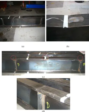
For both sections, some similar features in terms of flexural behaviour were observed. In particular, during the tests the specimens experienced well distributed local buckling waves on the compression flange, see as an example Fig. 7a. This was expected because of the absence of an intermediate stiffener capable of increasing the critical buckling stress of the compression flange. Minor plasticization of the compression flange occurred early in the tests of RHFB-240 because more affected by imperfections introduced by the production process and more sensitive to local effects owing to small thicknesses. This led to a loss of stiffness early in the tests. Moreover, some minor plasticization was also observed outside the zone between the point loads owing to local imperfections associated with still significant bending moment close to the constant bending moment region, as illustrated in Fig. 6c-d and Fig. 7b. Nonetheless for each specimen, the eventual failure was caused by a formation of a main spatial plastic mechanism inside the zone of constant bending moment, as depicted in Fig. 6a-b and Fig. 7c-d. Particularly for RHFB-300, web buckling was also observed, as noticeable in Fig. 7d.
36
(a) (b)
(c)
(d)
Fig. 6. RHFB-240: a) T02 failure mode; b) T02 enlargement of the main plastic mechanism at failure; c) T03 minor plasticization outside the point loads (left), main plastic mechanism at
37
(a) (b)
(c) (d)
Fig. 7. RHFB-300: a) T06 local buckling; b) T04 main spatial plastic mechanism; c) T04
38
Fig. 8. RHFB-240: bending moment-displacement curves.
Fig. 9 RHFB-300: bending moment-displacement curves.
40
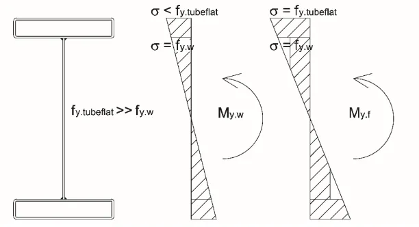
Fig. 10. Stress distribution assumed for computing the section elastic bending moment.
The results of the tests are summarised in Table 4 where the ultimate load (Pu), the
ultimate bending moment (Mu), the vertical displacement at maximum load (δu) and
the mass per unit length (g) of the specimens based on measured geometries are provided. The outcomes show that use of such profiles can be appealing in terms of the ratio flexural performance/weight in lieu of small hot rolled steel sections. In this respect, an estimate of weight savings is provided by determining through calculation the section modulus of IPE sections that would guarantee the average ultimate moment reached in tests by RHFBs considering the actual tube flat yield strengths: an IPE160A with mass per unit length equal to 12.7 kg/m, i.e. about +20% with respect to gRHFB-240, would be equivalent to the tested RHFB-240 section; and an IPE220 with g = 26.2 kg/m, i.e. about +25% with respect to g300, is comparable to the tested RHFB-300 section.
Table 4. Flexural performance of RHFBs.
Pu (kN) Mu (kNm) δu (mm) g (kg/m)
T01 RHFB-240 43.0 32.3 37.6 10.0
T02 RHFB-240 43.6 32.7 37.7 10.4
T03 RHFB-240 44.5 33.4 37.8 10.4
T04 RHFB-300 128.0 96.0 34.2 21.2
T05 RHFB-300 129.7 97.3 37.9 21.0
T06 RHFB-300 125.6 94.2 32.7 21.6
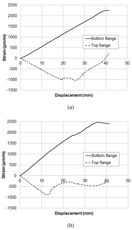
41 This phenomenon occurred at essentially the same compressive strain level for both sections because one of the key parameters that govern plate elastic buckling, i.e. the local slenderness ratio of the tube flange - b / t ≈ 50 -, is the same. Moreover, it is interesting to note that the theoretical elastic critical buckling strain εcr.thr of the tube outermost flange considering kσ = 4 is about equal to 1.45‰ [24]. A lower experimental value of strain at which plate buckling occurred, εcr.exp, is consistent considering the presence of imperfections and residual stresses.
(a)
(b)
42
5 NUMERICAL MODELLING
The numerical model was developed to perform nonlinear analyses of the tests and was used to expand the available findings over a wider slenderness range through parametric studies. The multipurpose finite element software ANSYS [25] was employed. Model geometry, application of loads, boundary conditions and material properties were implemented to seek consistency with the real setup, actual dimensions of the specimens and mechanical properties of steel. All the assumptions and schematizations will be discussed in detail in Subsection 5.1-5.3.
5.1 Geometric model
All beams tested in the experimental campaign – T01, T02, T03, T04, T05 & T06 - were modelled through FE analysis. Shell elements were used in order to fully grasp all the main phenomena that govern the behaviour of the beam under bending, such as local buckling and plasticity diffusion [13]. The Shell 181 element of the ANSYS library [25] was used to model all the parts of the profile, i.e. the rectangular hollow flanges, the central web, the web stiffeners located at supports and at load points as well as the plates at supports, as shown in Fig. 12. The Shell 181 element is a four-node element with six degrees of freedom at each node. It is well suited for moderately thick elements and for large rotation and/or large strain nonlinear applications. It is shear flexible and uses a uniform reduced integration method [25].
Fig. 12. FE model of the RHFB-240.
43
Fig. 13. Mesh refinement and restraint conditions located at the base of the plate that
redistributes reaction forces at supports.
The geometry of each numerical model was developed consistently with the measured dimensions because small deviations from nominal values were detected, as described in Section 2.1. Local imperfections were not directly measured; nonetheless, they were introduced by means of an elastic buckling analysis. In particular, the lowest local buckling mode shape involving the compression flange was introduced into the model, as depicted in Fig. 14.
Fig. 14. Lowest local buckling mode shape of the compression flange.
44 [22]. In this respect, the maximum amplitude was assumed as a function of the element width according to the Eq (1) [22]:
0.006
d = w (1)
where w is the element width and d represents the maximum imperfection amplitude. Analyses with different values of amplitude introduced in the web and in the top tube were performed and the ultimate load was compared with the experimental one. The amplitude values that better agreed with the experimental ultimate load corresponded to the maximum amplitude values as given in Eq (1) and they were then retained in all numerical simulations. For instance, the imperfection amplitude of the tube flange is about d = 0.6 mm for RHFB-240 and d = 0.9 mm for RHFB-300, respectively. In order to consider possible antisymmetric local buckling loads, the whole specimens were modelled.
5.2 Application of loads and restraints
Restraints were applied to the plates that were used to distribute the reaction forces at supports. In detail, a roller and a hinge were modelled at the supports by assigning the relevant condition to all nodes along a line strip below the plate support located underneath the bottom tube flange, as illustrated in Fig. 13. The plate and the bottom tube flange were connected together by means of rigid constraint equations – CERIG command [25] -. Finally, in order to prevent lateral torsional buckling and consistently with the experimental setup, restraints against horizontal displacement were punctually introduced along the top tube flange.
The load was applied by imposing increasing vertical displacement to the nodes of the web stiffeners located at half meter from the midspan. In this way, the evolution of the softening branch could be followed.
5.3 Material properties
The material mechanical properties implemented into the numerical model were derived directly from tensile tests on beam specimens drawn from the web and the tube flats. The cold working enhancement was not included in the corner zones because the membrane residual stresses were not modelled: in fact, they tend to counteract one another [22,26] as described in Section 4. The material constitutive law included the flexural residual stresses, as described in Section 2. True stress – strain relationships were employed for material properties because more representative of the state of material in large strain analyses. They read [25]:
(
1)
t e e
σ =σ +ε (2a)
(
)
ln 1
t e
ε = +ε (2b)
45 The Poisson’s ratio was taken equal to 0.30. The Multilinear Isotropic Hardening (MISO) material law was used for implementing the true stress – strain data. It allows including a user-defined stress-strain relationship by means of several linear segments. The MISO material is suitable for steel modelling because it relies on the Von Mises yield criterion. Moreover, an isotropic hardening rule was deemed adequate for the purpose because of the monotonic nature of the experimental tests.
5.4 Analysis of the results
In order to verify the accuracy of the numerical model, the ultimate moment capacity and the failure mode obtained from the numerical analyses were compared with the test outcomes. From Table 5 it is possible to observe that good agreement between numerical and experimental results was achieved by comparing the ultimate moment capacity Mu and the displacement δu at Mu. Moreover, the mode of failure that involved the main spatial plastic mechanism of the top compression flange was well captured for both sections profiles, as illustrated in Fig. 15a-d. Fig. 15e-f show that web buckling was also well represented by the numerical models of RHFB-300 specimens. However, looking in detail at the mode of failures depicted in Fig. 15g-h, the FE model of the RHFB-240 specimens was not capable of detecting some minor plasticization mechanisms occurred early in the tests. As stated above, these profiles were more affected by imperfections and by local effects owing to smaller thicknesses and the production process. This phenomenon determined an increase in deformability of the specimens that is shown by the difference in elastic branch behaviour between tests and numerical analyses, as illustrated in Fig. 16a-c. This is more evident in T02 RHFB-240 and T03 RHFB-240, whilst for T01 RHFB-240 the bending moment at which the formation of a minor plastic mechanism occurs, is delayed and clearly highlighted by sudden deviation from linear behaviour. Nevertheless, the ultimate values of RHFB-240 numerical analyses were not significantly affected. In RHFB-300 tests, early minor local plasticization was not detected, and the numerical elastic behaviour well agrees with the experimental one, as illustrated in Fig. 16d-f.
Table 5. Comparison of the flexural behaviour between numerical and experimental results.
Mu,FE / Mu,TEST δu,FE / δu,TEST
T01 RHFB-240 1.02 0.90
T03 RHFB-240 1.05 0.93
T04 RHFB-240 1.04 0.93
T05 RHFB-300 1.03 0.98
T06 RHFB-300 0.98 0.81
T07 RHFB-300 1.04 0.95
Average 1.03 0.92
46
(a) (b)
47
(e) (f)
(g)
(h)
Fig. 15. Comparison of the mode of failure: a) main plastic mechanism RHFB-240 test; b) main
plastic mechanism RHFB-240 FE; c) main plastic mechanism RHFB-300 test; d) main plastic mechanism RHFB-300 FE; e) web buckling RHFB-300 test; f) web buckling RHFB-300 FE; g)
48
(a)
(b)
49 (d)
(e)
(f)
Fig. 16. Comparison of bending moment-displacement curves: a) T01 RHFB-240; b) T02
50
6 PARAMETRIC STUDIES
51 (a)
(b)
Fig. 17. Parametric analysis: a) RHFB-240; b) RHFB-300.
Furthermore, the capability of the DSM [2] to predict the flexural behaviour of RHFBs was investigated. The main idea behind this method is the determination of all elastic instabilities, i.e. local Mcrℓ, distortional Mcrd, global buckling Mcre and the bending
moment that causes yield, i.e. My. The smallest moment among Mcrℓ, Mcrd, Mcre and My
identifies the bending resistance of the section. Since lateral-torsional buckling and lateral-distortional buckling do not apply to the case study, only local buckling is considered, as illustrated in the finite strip solution depicted in Fig. 18 [29]. It is worth to point out that for comparison purposes input data of finite strip analyses in terms of geometry of the cross section and mechanical properties, i.e. yield strength, elastic modulus and Poisson’s coefficient, were chosen consistently with the FE analyses. The stress distribution was assumed according to the My.f. No imperfections were included
52
Fig. 18. Finite strip analysis of a RHFB-240 profile with thickness equal to 1.4 mm.
7 CONCLUSIONS
The article reported the results of a comprehensive experimental-numerical study on cold-formed laterally-restrained steel rectangular hollow flanges beams (RHFBs) that was carried out in order to investigate their flexural capacity. The behaviour of RHFB-300 specimens was influenced by a significant difference in yield strength between the tubes and the web that induced local buckling and plastic behaviour in the web. All experimental tests showed well-distributed local buckling waves on the compression top flange. Some minor plasticization was observed outside the zone between the point loads owing to local imperfections associated with still significant bending moment close to the constant bending moment region. Furthermore, the RHFB-240 profiles exhibited minor plasticization, that caused an early loss of stiffness, prematurely in the tests because more prone to be affected by local imperfections and by local effects that were emphasized by a lack of opt