Active & Reactive Power Control of DFIG
Sateesh SukhavasiAssociate Professor, Adama Science & Technology University, Adama, Oromoia Region, Ethiopia
Abstract— Wind Energy is gaining interest now-a – days as one of the most important renewable sources of energy due to its eco-friendly nature. But the major disadvantage lies in variable speed wind generation and this paper gives a study on control of Wind driven doubly fed Induction Generators. With the use of bidirectional power flow converter, speeds above and below synchronous speeds can be obtained. By using this reactive power is controlled and hence the overall Power factor of system can be kept at unity under varying load conditions. . This paper presents simulation results of a Grid-connected DFIG. This paper proposes a switch-by-switch representation of the PWM converters with a carrier-based Sinusoidal PWM modulation for both rotor- and stator-side converter. Stator oriented FOC or vector control approach is deployed for both stator- and rotor-side converters to provide independent control of active and reactive power and keep the DC-link voltage constant. Simulation is carried out for 7.5 KW generator. Active and reactive power control is verified both above and below synchronous speeds for its effectiveness.
Keywords - Active and Reactive Powers, DFIG (Doubly fed Induction Generator), Grid side Converter (GSC), Rotor Side Converter(RSC), Stator Flux Oriented control.
A. Nomeclature
Stator and rotor voltages Stator and rotor currents
Stator and rotor flux linkages
,
Machine magnetizing reactance, inductance.Per phase stator and rotor winding inductances
Per phase stator and rotor leakage inductances
Per phase stator and rotor winding resistances
Leakage factor
Stator and rotor apparent power Stator and rotor active power
Stator and rotor reactive power
Net active & reactive powers of wind turbine
Grid frequency
Space phasor modulus of stator magnetizing current
Space phasor modulus of rotor current Reference value of stator side active power
Reference value of stator side reactive power
Rotor current components, direct-and quadrature-axis respectively and expressed in the stator reference frame Respectively the reference values of the
rotor current components. Direct- and Quadrature– axis rotor
current components expressed in the rotor natural reference frame.
Direct – and quadrature- axis stator current components expressed in the stationary reference frame
Direct – and quadrature – axis stator current components expressed in the stator- flux- oriented reference frame PI compensator parameters of the inner
loop vector controller
PI compensator parameters of the outer loop vector controller
Direct- quadrature-axis stator magnetizing current components expressed in the stationary reference frame
Direct- and quadrature- axis rotor decoupling voltage components expressed in the stator- flux- oriented reference frame
Direct- and quadrature- axis rotor
voltage components expressed in the stator- flux- oriented reference frame
Direct- and quadrature- axis rotor
voltage components expressed in the rotor natural reference frame
Space phasor modulus of stator current
Direct- and quadrature- axis stator
voltage components expressed in the stationary reference frame
Copyright © 2014 IJCTET.IN, All right reserved Angular slip frequency
Direct- and quadrature- axis rotor voltage components expressed in the stationary reference frame
DC Link Voltage Reference Value Quadrature axis reference current
Stator voltage at Phase A
Stator voltage at Phase B Stator voltage at Phase CB. Suffices, Superscripts
s, r
Stator, rotor, β
, β Stationary reference framed, q
d-q reference frame
x, y
x, y stator-flux-oriented reference frame
a,b,c
Three-phase reference
Introduction
Industrial drive applications are generally classified into constant speed and variable speed operations. For constant speed applications generally ac machines are used where as for variable speed applications dc machines are used. But due to the disadvantages of dc machines lies mainly with commutators and brushes which limit the machine speed and peak current. As a result for variable speed applications ac machines are gaining more important than the dc machines recently. In order to meet power needs, taking into account economical and environmental factors, wind energy conversion is gradually gaining interest as a suitable source of renewable energy. With increased penetration of wind power into electrical grids, wind turbines are largely deployed due to their variable speed feature and hence influencing system dynamics [10]. But unbalances in wind energy are highly impacting the energy conversion and this problem can be overcome by using a Doubly Fed Induction Generator (DFIG) [1, 23].
Doubly fed wound rotor induction machine with vector control is very attractive to the high performance variable speed drive and generating applications [13]. In variable speed drive application, the so called slip power recovery scheme is a common practice here the power due to the rotor slip below or above synchronous speed is recovered to or supplied from the power source resulting in a highly efficient variable speed system [2]. Slip power control can be obtained by using popular Static Scherbius drive for bi directional power flow. The major advantage of the DFIG is that the power electronic equipment used i.e. a back to back converter that handles a fraction of (20-30%) total system power [16]. The back to back converter consists of two converters i.e. Grid Side Converter (GSC) and Rotor Side Converter (RSC) connected back to back
through a dc link capacitor for energy storage purpose [3, 19].
In this paper a control strategy is presented for DFIG. Stator Active and Reactive power control principle is also presented. In order to decouple the active and reactive powers Stator Flux Oriented control is used and hence the induction machine model is developed, PI Controllers design is applied for stator flux oriented reference frame [14, 24]. The simulation model is developed and implemented in MATLAB/SIMULINK software [24].
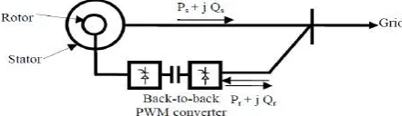
Fig. 1. Doubly Fed Induction Generator Driven by a Wind Turbine.
Principle of Operation
Fig. 2 shows the basic scheme adopted in the majority of systems. The stator is directly connected to the AC mains, whilst the wound rotor is fed from the Power Electronics Converter via slip rings to allow DIFG to operate at a variety of speeds in response to changing wind speed. Indeed, the basic concept is to interpose a frequency converter between the variable frequency induction generator and fixed frequency grid. The DC capacitor linking stator- and rotor-side converters allows the storage of power from induction generator for further generation. To achieve full control of grid current, the DC-link.
Fig. 2. Schematic Diagram of a Doubly Fed Induction Generator.
synchronous speed in the motoring mode, rotor-side converter operates as an inverter and stator-side converter as a rectifier, where slip power is supplied to the rotor. At the synchronous speed, slip power is taken from supply to excite the rotor windings and in this case machine behaves as a synchronous machine.
Wind Turbine Model
Several models for power production capability of wind turbines have been developed. The mechanical power, captured Pmech by a wind turbine, depends on its power coefficient Cp given for a wind velocity and can be represented by
(1)
Where and correspond to the air density and the radius of the turbine propeller, respectively. The power coefficient can be described as the portion of mechanical power extracted from the total power available from the wind, and it is unique for each turbine. This power coefficient Cp is generally defined as a function of the tip-speed-ratio which, in turn, is given by
(2)
Where ω represents the rotational speed of the wind turbine. Fig. 3 shows a typical relationship between the power coefficient Cp and the tip-speed-ratio. It should be noted that there is a value of to ensure a maximum of Cp . Thus, it can be stated that, for a specified wind velocity, there is a turbine rotational speed value that allows capturing the maximum mechanical power attainable from the wind, and this is, precisely, the turbine speed to be followed.
Fig. 3. Typical Power Coefficient Versus Tip-Speed-Ratio Curve.
The method followed in this paper in order to reach the optimum tip-speed-ratio at each wind velocity consists in, based on the generator rotor speed, estimating and, therefore, trying to achieve the optimum active power to be generated by means of the rotor current stator-flux-oriented vector control.
Specifically, assuming that the optimum power coefficient Cp and, as a result, the optimum tip-speed-ratio values for the particular wind turbine employed are properly identified, the stator side active power reference Ps ref value which is made equal to is established
starting from the turbine ω angular speed through
equations (1) and (2).
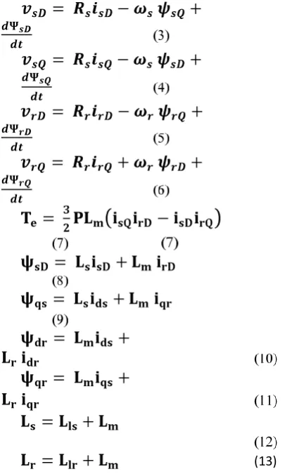
Dynamic Simulation of DFIG in Terms of
dq-windings
The dynamic performance of ac machine is somewhat complex because the three phase rotor windings move with respect to three phase stator windings. Hence a three phase machine can be represented with an equivalent two phase machine replacing the variables associated with the stator windings of a machine with variables associated with fictious windings rotating with the rotor at synchronous speed. The analysis can be simplified greatly by transforming the three phase stator and rotor windings(with angular displacement) to a fictious two phase stator and rotor(with no displacement).These fictious two phase windings are called d-q windings.The stotor and rotor a-,b- and c-phase voltage equations can be transformed to the d-q axis.Then the generator electrical model is derived from the following equations.
(13)
Active & Reactive Power Control of DFIG
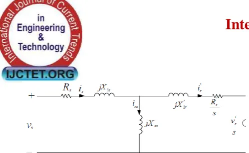
Per phase equivalent for a DFIG is shown in the fig.4.Variables with the „notation denote rotor quantities as
Copyright © 2014 IJCTET.IN, All right reserved
Fig. 4. Per Phase Equivalent Circuit of a DFIG.
By neglecting the effects of Rs, jXls and jXlr the per phase stator power Ss and rotor power Sr can be expressed as
(14)
(15)
The active and reactive powers are found by using the Equations as below.
(17)
Control Scheme of DFIG
A. Stator Flux Oriented Vector Control Principle
Vector control can also possible with air gap flux or stator flux orientation, but at the cost of a coupling effect that demands decoupling compensation. Stator flux oriented direct vector control has the advantage that flux vector estimation accuracy is estimated by the stator resistance Rs variation only. In this control we developed a strategy for stator flux oriented vector control by using the equations derived from d-q equivalent circuits. If the stator flux is oriented on the d-axis, then the flux q-axis
component Ψqs = 0. Fig. 4. Shows the stator flux phasor diagram represented in d-q frames rotating at
synchronous speed ωs.
The following steps are used to implement the stator flux oriented principle and shown in Fig. 5.
a) By using Clarke‟s transformation both the stator
and rotor side three phase currents are converted in to two phase currents.
(18)
(19)
b). The stator flux linkage space phasor angular position with respect to the stationary direct axis is estimated by using the following equations.
(20)
(21)
(22)
(23)
(24)
Fig. 5. Overall Control Structure of a DFIG
c). Voltage components to be applied to the rotor side are generated by means of two identical PI controllers as shown below.
(25)
(26)
rx
(27)
ry
(28)
d). In order to improve the decoupling between x & y axes, the and decoupling voltage components given below are added to rx and ry respectively.
(29)
(30)
(31)
(32)
(33)
The resultant voltages in both axes will be referred to as and .
(34)
(35)
f). By using Inverse Clarke‟s transformation the rotor
three phase voltages are obtained from two phase to three phase.
(36)
P
B. Controllers Design
The DFIG control structure consists of two cascaded control loops. The outer one governs the stator active and reactive powers, so that the power factor value
determined by the electric energy distribution company is complied with as accurately as possible. Simultaneously, it would be convenient to employ profitably provided by the wind at each moment from the income yield capacity point of view.
Then the rotor circuit can be represented in d-q frames by the transfer function given in equation
(38)
Where σ is the leakage factor
(39)
(40)
The PI controllers transfer function is given as
Fig. 6. Active and Reactive Power Outer Control Loop Design.
C.
Modeling of DFIG in
MATLAB/SIMULINK
Closed Loop diagram of DFIG by using Back to Back PWM Converters
In the area of wind energy production, machines of medium and high power which are mainly used. Thus, the stator resistance was neglected. By using the stator flux oriented principle the stator flux is oriented on the d-axis, then the flux q-axis component.
(41)
(42) Hence the stator voltage can be written as
By using the above equation expression for electromagnetic torque becomes as
(45)
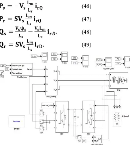
According to Torque equation (45), the electromagnetic torque of the DFIG can be controlled by controlling the q-axis rotor current iqr. Using the vector control, the active and reactive powers of the DFIG can be expressed as follows.
Fig. 7. Closed Loop Diagram of a DFIG in Simulink Model.
Copyright © 2014 IJCTET.IN, All right reserved
Fig. 8. Power Control of DFIG.
b)Rotor Side Converter Control
The control principle of the rotor side converter (RSC) allows the control of active and reactive power and the extraction of maximum wind power as shown in Fig. 10.
Fig. 9. Control Structure of Rotor Side Converter.
Fig. 10. Control Structure of Grid Side Converter Control.
c) Grid Side Converter Control
The Grid Side Converter (GSC) ensures the regulation of the DC bus voltage and adjusts the power factor on the grid side. The GSC is a bidirectional converter which operates as a rectifier when the slip (S) is positive (sub synchronous mode) and as an inverter when the slip is negative (super synchronous mode). Fig. 10 shows the schematic control of a Grid Side Converter Control.
Simulation Results
Fig. 11. Stator Voltage & Current in Phase ‘A’.
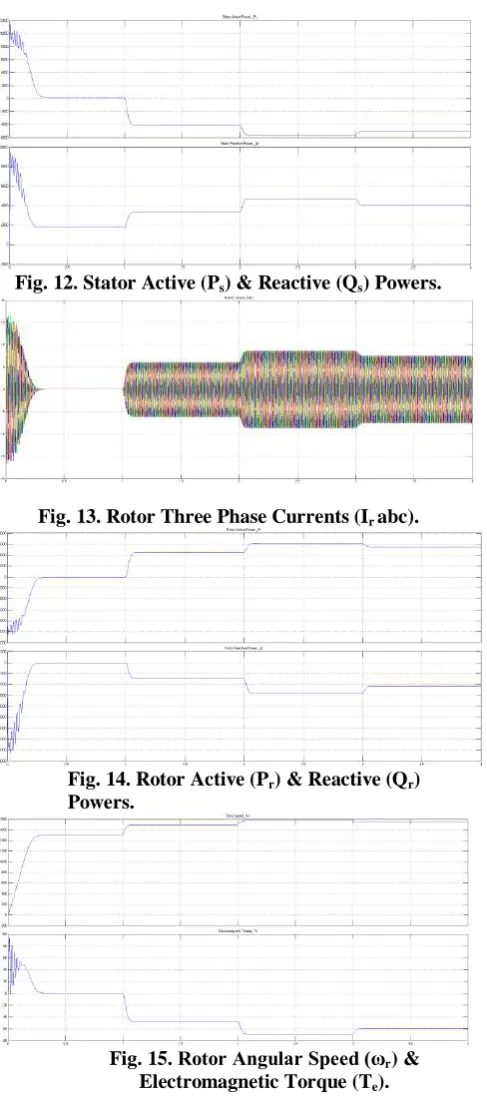
Fig. 12. Stator Active (Ps) & Reactive (Qs) Powers.
Fig. 13. Rotor Three Phase Currents (Ir abc).
Fig. 14. Rotor Active (Pr) & Reactive (Qr) Powers.
Fig. 15. Rotor Angular Speed (ωr) & Electromagnetic Torque (Te).
Conclusion
for the given input. Hence from these results we can determine that for super synchronous speeds the torque is negative (generating) and for sub synchronous speeds it is positive (motoring).As a result the active & reactive powers are controlled by using the stator flux oriented principle which yields the better results. The machine side provides good decoupling between active and reactive powers.
Appendix
Wound Rotor Induction Machine Parameters:- Nominal Power Pn = 7.5 Kw Stator Voltage Vs = 415 V Stator Frequency fs = 50 Hz Stator Resistance Rs= 7.83 Ω Stator Inductance Ls = 0.4751 H Rotor Resistance Rr= 7.55 Ω Rotor Inductance Lr = 0.4751 H Mutual Inductance Lm = 0.4535 H Inertia Constant J = 0.06 Kg-m2 No. of Pair of Poles P =2 Rated Speed Nr = 1440rpm
References
[1] Brahim Nait-kaci, Mamadou L. Doumbia, “Active and Reactive power control of a doubly fed
induction generator for wind applications”, IEEE
2009. (reference1).
[2] Arantxa Tapia, Gerardo Tapia, J. Xabier Ostolaza,
“Modeling and Control of a Wind Turbine Driven doubly fed Induction Generator”, IEEE 2003.
(reference2).
[3] C. Eisenhut, F. Krug, C. Schram and B. Klockl,
“Wind Turbine Model for System Simulations
Near Cut-in Wind Speed” IEEE Trans, on Energy Conversion, June 2007, vol. 22, 414-420.
[4] T.K.A. Brekken “A Novel Control Scheme for a Doubly-Fed Induction Wind Generator under
Unbalanced Grid Voltage Condition.” 2005.
[5] A. Peterson “Analysis, Modeling and Control of Doubly fed Induction Generators for Wind
Turbines,” in Energy and Environment. 2005, PhD
Dissertation thesis, Chalmers University of Technology: Goteborg.
[6] J. Morren, J.T.G. Pierik, S.W.H. De Haan, J.
Bozelie, “Grid Interaction of offshore Wind Frames. Part 1. Models for Dynamic Simulation,”
Wind Energy, 8(3), July-Sep 2005.
[7] A.D. Hanseen, “Generator and power electronics
for wind turbine” Chapter in Wind Power in Power
Systems, John Wiley and sons Ltd., 2004
[8] L. Holdsworth, Wu. XG, J.B. Ekanayake, N.
Jenkins, “Comparison of fixed speed and doubly
-fed Induction Wind Turbines during Power System
Disturbances.” IEE Proceedings: Generation,
Transmission, Distribution, 2003, 343-352. [9] A. Tapia “Modeling and Control of a wind turbine
driven doubly fed induction generator.” Energy
Conversion, IEEE Transaction on, 2003, 194-204. [10] W.L. Kling and J.G. Slootweg, “Wind Turbines as
Power Plants” in Proceeding of the IEEE Wind
Power and the impacts on Power Systems June 2002, 17-18, Oslo, Norway.
[11] JM. Rodriguez, “Incidence on Power System dynamics of high penetration of fixed speed and
doubly fed wind energy systems,” IEEE
Transaction on Power Systems, 2002, 1089-1095. [12] S. Wade, M.W. Dunnigan, and B.W. Williams,
“Modeling and simulation of induction machine vector control with rotor resistance identification,”
IEEE Trans. Power Electron., vol. 12, pp. 495- 50, May 1997.
[13] D.J. Atkinson, R.A. Larkin, and R. Jones, “A vector-controlled doubly- fed induction generator for a variable- speed wind turbine application,” Trans, Inst, Meas, Contr., vol.19, no. 1, 2-12, 1997. [14] R.S. Pena, J.C. Clare, and G.M. Asher, “Vector control of a variable speed doubly-fed induction
machine for wind generation system, EPEJ” vol. 6,
no 3-4, 60-67, Dec.1996.
[15] R. Pena, J.C. Clare, G.M. Asher, “Double fed Induction generator using back-to-back PWM converters and its application to variable-speed wind-energy generation”. Electric Power Applications, IEE Proceedings 1996. 143(3), 231-241.
[16] W.C. Xu “Torque and reactive power control of a Doubly-Fed induction machine by Position sensor
less scheme”. IEEE Trans. Industrial Applications,
1995. 31(3), 636-642.
[17] Ana I. Estanqueiro “A dynamic wind generation
model for power system studies”. IEEE
transactions on power system, vol 22, No.3, August 2007.
[18] Z.Liu, O.A.Mohammed “A Novel Direct Torque Control of Doubly-Fed Induction Generator Used for Variable Speed Wind Power Generation” IEEE transactions 1-4244-1298-6/07, 2007.
[19] Joseph Kearney, Michael F Conlon, Eugene Coyle
“The Integrated Control of the Rotor Side and Grid Side Converters in a DFIG to Reduce Both Power and Torque Pulsations During Network Voltage
Unbalance Conditions”
978-0-947649-44-9/09/$26.00 ©2009 IEEE
[20] Jihen Arbi, Manel Jebali-Ben Ghorbal, Ilhem Slama-Belkhodja and Lotfi Charaabi “Direct Virtual Torque Control for Doubly FedInduction
Generator Grid Connection” IEEE Transactions on
Copyright © 2014 IJCTET.IN, All right reserved [21] Jeong-lk Jang, Young-Sin Kim and Dong-Choon
Lee “Active and Reactive Power Control of DFIG
for Wind Energy Conversion under Unbalanced
Grid Voltage” 1-4244-0449-5/06 ©2006 IEEE.
[22] A.P. Tennakoon1, A. Atputharajah, and S.G. Abeyratne, and J.B. Ekanayake “Doubly-fed Induction generators for wind power generation
“Second International Conference on Industrial and Information Systems, ICIIS 2007, 8 – 11 August 2007, Sri Lanka.
[23] Lie Xu “Coordinated Control of DFIG‟s Rotor and Grid Side Converters During Network Unbalance” IEEE Transactions on power electronics, Vol. 23, No. 3, May 2008
[24] Yao Xing-jia, Liu Zhong-liang, and Cui Guo-sheng “Decoupling Control of Doubly-Fed Induction Generator based on Fuzzy-PI
Controller” 2010 International Conference on
Mechanical and Electrical Technology (ICMET 2010).
[25] Jeferson Marques and Humberto Pinheiro
“Dynamic Behavior of the Doubly-Fed Induction
Generator in Stator Flux Vector Reference Frame”
0-7803-9033-4/05©2005 IEEE.