R E S E A R C H A R T I C L E
Open Access
FFT-based interface decohesion modelling
by a nonlocal interphase
Luv Sharma
1, Ron H. J. Peerlings
1*, Pratheek Shanthraj
2, Franz Roters
2and Marc G. D. Geers
1*Correspondence: [email protected]
1Department of Mechanical
Engineering, Eindhoven University of Technology, P.O. Box 513, 5600 MB Eindhoven, The Netherlands
Full list of author information is available at the end of the article
Abstract
In this paper, two nonlocal approaches to incorporate interface damage in fast Fourier transform (FFT) based spectral methods are analysed. In FFT based methods, the discretisation is generally non-conforming to the interfaces and hence interface elements cannot be used. This limitation is remedied using the interfacial band concept, i.e., an interphase region of a finite thickness is used to capture the response of a physical sharp interface. Mesh dependency due to localisation in the softening interphase is avoided by applying established regularisation strategies, integral based nonlocal averaging or gradient based nonlocal damage, which render the interphase nonlocal. Application of these regularisation techniques within the interphase
sub-domain in a one dimensional FFT framework is explored. The effectiveness of both approaches in terms of capturing the physical fracture energy, computational aspects and ease of implementation is evaluated. The integral model is found to give more regularised solutions and thus a better approximation of the fracture energy. Keywords: FFT-based spectral methods, Interfaces, Damage, Nonlocality
Introduction
Polycrystalline materials at a microscopic level show clear heterogeneous deformation patterns. This heterogeneity arises from the locally fluctuating mechanical properties of different phases and differences in lattice orientations between different grains.
FFT based spectral solver was originally introduced to model the mechanical behaviour of composite microstructures [1]. Since then it has emerged as a promising tool for mod-elling the micromechanical response of polycrystalline materials [2,3]. A comparison of different FFT formulations and solution approaches in a crystal plasticity constitutive framework [4] was presented in [5]. Recently, an FEM perspective on an FFT based spec-tral formulation for small strain non-linear material behaviour was given in [6] and its extension to a finite strain setting was presented in [7]. Alongside such improvements, much effort has gone into making the method suitable for various applications. The com-putational efficiency of FFT methods makes them attractive to solve multi-field problems, for e.g. a nonlocal crystal plasticity formulation [8], ferroelectric switching [9], etc.
Polycrystalline microstructures show a combination of intergranular and intragranular damage. Gradient based nonlocal damage simulations in a polycrystalline material were performed using an FFT approach in [10] without differentiating between bulk dam-age and interface decohesion. Interfaces like phase boundaries and grain boundaries are
©The Author(s) 2018. This article is distributed under the terms of the Creative Commons Attribution 4.0 International License (http://creativecommons.org/licenses/by/4.0/), which permits unrestricted use, distribution, and reproduction in any medium, provided you give appropriate credit to the original author(s) and the source, provide a link to the Creative Commons license, and indicate if changes were made.
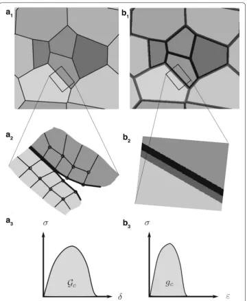
Fig. 1 Methodology for modelling a polycrystalline interface in finite element method (a1–a3) and FFT
based solvers (b1–b3). a1shows a polycrystal with interface elements embedded at sharp boundaries. a2
depicts an interface conformal finite element mesh with cohesive zones that open during loading according to the traction (σ)—separation (δ) law shown in a3with characteristic fracture energyGc. b1shows the same
polycrystal with interfacial bands representing the sharp interfaces. An example constitutive behaviour for the material points (within the volumetric interphase) assigned dissipation densitygcis shown in b3
particularly susceptible to damage initiation and propagation. For example, damage nucle-ation in Dual Phase steel has been attributed to interface decohesion at ferrite–martensite phase boundaries and martensite cracking along prior austenite grain boundaries [11]. In our contribution, we focus on the computational treatment of interface decohesion and its interaction with the (undamaged) bulk behaviour in FFT solvers.
In finite element (FE) based solution schemes, such problems are generally tackled using cohesive zones [12,13], see Fig.1(a1, a2, a3). Interfaces are identified a priori and
FE discretisation is made to conform to the sharp interfaces. The opening behaviour of these interface elements is governed by a traction-separation law (TSL) that is assigned to them. FFT based spectral methods, however, rely on a regular grid and a method to include sub-dimensional (e.g. planar in 3D) elements cannot be used. Composite pixel based approaches, for example [14], which make use of the interface normal to assign homogenised mechanical properties to grid points near the interfaces, are a step in that direction. But at this point it is not clear how they will perform in situations of damag-ing interfaces that are inclined or curved. The high mechanical contrast combined with inherent pixelation effects of FFT may cause stresses relayed across damaging interfaces, which is undesirable for the modelling of cracks. This limitation is dealt with using the idea of an interphase (volumetric) band, as depicted in Fig. 1(b1, b2, b3). The material
points in the vicinity of the sharp interface are identified and furnished with a dam-age constitutive behaviour (softening) and corresponding kinematics—in addition to the deformation mechanisms attributed to them as a part of the respective grains they belong to. We aim to have multiple points across the thickness of the interphase. We expect this to reduce the pixelation effect and ensure that the two crack faces are fully decou-pled. This approach allows capturing the interfacial mechanics and still benefits from the computational (memory and speed) and implementation related advantages of FFT based methods. Such an approach to represent interfaces as interphase has been used previously in the literature. Hsueh-Hung et al. [15] used it to assign different material behaviour to grain boundary regions than the bulk. Their approach was physically motivated and directed towards understanding metal plasticity in the nanocrystalline regime. Clayton et al. [16] used this approach within a finite element implementation of phase field damage to understand the competition between intergranular and intragranular damage.
In volumetric dissipation based models, one specifies a dissipation density and an inter-nal length scale to the model—which for the present case is the band thickness,l. The total dissipation resulting from the volumetric damage process must equal the physical dissi-pation of the real sharp interface (or cohesive zone model). Accordingly, the dissidissi-pation density has to scale inversely with the band thickness. A straightforward inversely pro-portional relationship results if the entire interphase band damages uniformly. This is not guaranteed in a conventional local softening model due to localisation and lacking objec-tivity with respect to the grid spacing. Various regularisation strategies have been used in the literature to remedy this. They can broadly be classified into two categories—integral based averaging [17] and gradient damage based regularisation [18–22].
0
x1=−2l x2=2l
−L
2 L2
x Sharp Interface
Interphase band
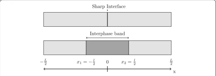
Fig. 2 1D bar with an interphase band (bottom) representation of a central sharp interface (top)
In “Results and discussion” section, results of both the approaches are discussed. A con-clusion and outlook is presented in “Concon-clusion and outlook” section.
Problem statement
Consider a 1D bar of lengthLas shown in Fig.2. Let us assume a sharp interface at the center (x = 0) of the bar. To capture the response of this interface using an FFT based spectral scheme, the sharp interface is substituted by a volumetric interphase band of thickness l spanning the region fromx1 = −2l tox2 = 2l. The elastic properties are
taken to be homogeneous, with Young’s modulus defined asE. To model the kinematics of decohesion, a damage strain field,εd(x), is introduced forx∈ΩiwhereΩi=(x1, x2) is
the sub-domain representing the interphase region in the total domainΩ = (−L/2, L/2). Since only the interphase region accommodates the damage strain, the damage constitu-tive model is only used inΩi. InΩiit is superimposed on the elastic strainεe(which exists onΩ) as,
ε=εe+εd. (1)
A local damage fieldφl(x), forx ∈ Ωi, is introduced. This field represents the material integrity. It is initialised to unity, representing a perfectly bonded state. When the damage evolves it drops towards zero, thereby reducing the capacity of a material point to transmit stresses. A damage constitutive model exploiting only the local fieldφlis ill-posed and pro-vides non-physical results due to a pathological tendency to localisation [17]. Therefore, a nonlocal counterpart field,φnl, is defined also forx∈Ωi.
The bar is subjected to an overall monotonic uniaxial tensile loading at a constant rate ˙¯
ε. This loading rate is related to the local strain rate field as
˙¯
ε= 1
L
+L
2
−L 2
˙
εdx, (2)
The stress at equilibrium has to satisfy,
∂ σ
∂x =0. (3)
Constitutive model
The constitutive model relating the stress and the elastic strain for all material points at
σ =Eεe. (4)
The evolution law forεdis taken as
˙
εd =ε˙d0
|
σ| σcφnl2
−1
2
sgn (σ), (5)
whereσcφnl2is the effective opening resistance, withσcthe critical stress of the model; ˙
εd0is the reference opening rate. The Macaulay brackets, defined as· = (· + |·|)/2,
make sure that the damage strain does not evolve untilσreaches the initial critical stress
σc. The nonlocal damageφnl, in Eq. (5) is obtained by appropriately regularizing the local damage fieldφldefined as
φl =
1−εd
εf
. (6)
The critical damage strainεf governs the softening slope. It is noted that the rate depen-dent form depicted in Eq. (5) is motivated from the sub-scale mechanics (micro-void formation, plasticity etc.).
Analytical solution for the rate-independent case
Since the applied loading is monotonic tension, one can rewrite Eq. (5) beyond the damage threshold as
σ =σcφnl2
1+ ˙ εd ˙
εd0
1
2
. (7)
In order to retrieve an analytical solution, a special case is considered. It is assumed that the nonlocal field coincides with the local field, which is furthermore assumed to be uniform within the interphase band. In this case we have, also using Eq. (6),
σ =σc
1−εd
εf 2 1+ ˙ εd ˙
εd0
1
2
. (8)
In the rate-independent limit, implying
˙
εd <<ε˙d0, (9)
Equation (8) yields
σ =σc
1− εd
εf
2
. (10)
Due to the equilibrium condition in this 1D setting, a spatially constant stress field results. The average strain ¯εfor any instant after the damage has initiated can be obtained by inverting Eq. (10) to giveεd as a function ofσ and integrating the elastic and damage contributions to the strain field:
¯
ε= 1
L
L
0 εe dx+
x2
x1
εddx
= σ E + 1− σ σc 1 2 εf l
Thus, the overall stress–strain response for this rate-independent uniform damage case can be written in piecewise form as
¯
ε=
⎧ ⎪ ⎨ ⎪ ⎩ σ
E, if ¯ε≤ σEc
σ
E +
1−
σ σc
1
2
εfLl, otherwise.
(12)
The dissipation per unit volume due to the damaging process can be computed analytically as
gc=
εf
0
σdεd =σc
εf
0
1−εd
εf
2 dεd=
1
3σcεf, (13)
where use has been made of Eq. (10).
Relating the dissipation throughout the interphase volume to the expected interfacial dissipationGc, we obtain
gcl=Gc. (14)
Accordingly, the product of the damage constitutive parametersσcandεf should depend inversely on the interphase band thickness. This equality, together with Eq. (13), indicates how the strain to failure needs to be scaled with respect to the interphase band thickness
l, in order to recover the strength and dissipation of a cohesive zone, for arbitraryl:
εf = 3Gc σcl
. (15)
Gradient based nonlocal damage
In the differential form of nonlocality, the nonlocal damage field is determined as the solution of a differential equation. Here, the classical gradient based damage equation is considered to retrieve the nonlocal counterpart ofφl, which reads in one dimension:
∂ ∂x
λ2(x) ∂
∂xφnl
+φl−φnl =0, (16)
whereλ(x) is the nonlocal length scale. In principle, the damage variablesφnlandφlare meaningful only forx ∈ Ωi, and therefore Eq. (16) for the nonlocal fieldφnl should be solved on the sub-domainΩi only, with flux free boundary conditions (also referred as interface condition) on∂Ωi, i.e.
λ2∂φnl
∂x =0 onx∈∂Ωi, (17)
where∂Ωi = {x1, x2}. Since FFT solvers are based on global and periodic shape functions
with a regular discretisation grid, the problem has to be solved on the full domain instead, still respecting Eq. (17) at least approximately. This may be achieved by extending Eq. (16) to the entire domainΩ, but with a piecewise constantλ, equal to the desired valueλin inside the band and a much smaller valueλoutoutside the band. In that case, the interface condition at the edges of the interphase reads:
λ2∂φnl ∂x x−=
λ2∂φnl
which corresponds with Eq. (16). In the limit of λin/λout → ∞ this condition enforces Eq. (17). In practice, a finite, but large, contrastλin/λout is used and Eq. (17), the flux free boundary condition, is satisfied only approximately.
Phase field approaches also provide a differential equation based continuum solution for evolution of damage. In principle, a phase field model based on a Ginzburg–Landau approach can be used as well, for example [21,23]. The resulting governing equations are similar to models based on the micromorphic approach, with an evolving length scale [24]. In fact, these approaches were introduced to avoid spurious spreading of the damage field (away from the nucleation point), which was observed when using a linear phase field potential in the former and a decreasing length scale in the latter.
In the present approach, based on the classical gradient based damage, the issue of compact support of damage field is avoided by using the length scale contrast to restrict the damage field to the interphase band. In order to recover physically meaningful results, which are objective with respect to the thickness of the interphase band, the interphase band needs to damage uniformly, even for bands that are not extremely thin. From this perspective, the classical gradient damage model provides better regularisation charac-teristics than these phase field approaches. If a phase field approach would be considered instead, models based on quadratic or double-well potential would suit best for the good regularisation characteristics needed in our application.
The numerical solution of the boundary value problem requires solving Eqs. (3) and (16) simultaneously. Note that these equations are coupled through the constitutive Eq. (5). Both differential equations are discretised using the FFT scheme. The coupled system of equations is solved using a staggered iterative scheme as detailed in an FEM context in [21]. The discretisation and residual evaluation of the mechanical equilibrium differential equation is well documented in [5]. Here, we only outline the residual formulation of the damage Eq. (16).
In order to avoid taking the Fourier transform of the length scale field, the non-linear residual is constructed by utilizing the fixed-point concept. We start by splittingλ2(x) into a homogeneous and a fluctuation field as
λ2(x)=λ¯2+λ˜2(x). (19)
Substituting Eq. (19) in Eq. (16) and taking the Fourier transform (F) we obtain
Fφnl−λ¯2F
∂2φ
nl ∂x2
=Fφl+F
∂
∂x
˜
λ2 ∂
∂xφnl
, (20)
which can also be written as,
Fφnl−λ¯2F
∂2φ
nl ∂x2
=Fφl+F
∂ ∂x
˜
λ2F−1F
∂ ∂xφnl
. (21)
Now using the property of the Fourier transform applied to differential operators, i.e,
F∂nf
∂xn =(ιk)nfˆ, the above equation can be rewritten as
ˆ
φnl−λ¯2(ιk)2φˆnl=φˆl+(ιk)F
˜
λ2F−1(ιk) ˆφ
nl
After some rearrangements and taking the inverse Fourier transform (F−1), Eq. (22) is
rewritten in residual form as
Rd =φnl−F−1
ˆ
φl+(ιk)F
˜
λ2F−1(ιk) ˆφ
nl
1−λ¯2(ιk)2
=0. (23)
Initialisingφnl≡1, Eq. (23) is solved using the matrix free Newton solver available in the PETSc library [25]. The frequencies used in the discrete Fourier transforms in this work correspond to the modifications presented in [26].
Integral based nonlocal damage
For the integral based nonlocal damage case, a weighted moving average is used to calculate the nonlocal fieldφnlfrom the local damageφl, i.e. [17,27].
φnl(x)=
ΩiΨ(y;x)φl(y)dΩ
ΩiΨ(y;x)dΩ
, (24)
where yis the position of the infinitesimal volumedΩ ∈ Ωi. The weighting function Ψ (y;x) that is commonly used is the Gaussian distribution, which reads
Ψ(y;x)=exp
−
(y−x)2 2λ2
, (25)
wherexis the position vector of the point at which the distribution is centred andλis the characteristic length, which determines the distance along whichΨ decays to zero. The denominator in Eq. (24) normalizes the weighting function, which ensures that for a homogeneousφl(x), the nonlocal fieldφnl calculated using Eq. (24) coincides with its local counterpart.
In our numerical setting, Eq. (24) is approximated by a cell averaging method, which can be written as
φnl i=
jφl jΨ((Δx(j−i))2)
jΨ((Δx(j−i))2)
, (26)
whereiandjrepresent material points in the interphase sub-domain andΔxis the grid spacing. Equation (26) can be implemented by looping over all the points inΩi. A more efficient way is to store the normalised weights in Eq. (26) in a matrix and implement the convolution via a matrix-vector product.
Results and discussion
0 0.2 0.4 0.6 0.8 1 1.2 1.4 1.6 1.8 2 2.2 2.4 0
0.2
0.4
0.6
0.8
1
x l
φnl
(λin/λout)2
101
102
103
104
Fig. 3 Nonlocal damage profiles for various length scale (λin/λout)2contrast at an instant when global stress
σhas dropped to 0.007σc
local damage model (φnl =φl) without imperfection. Given the piecewise uniform nature of this problem, the numerical solution for its calculation does not show localisation and thus does not need any regularisation.
Model parameters used
The numerical studies are performed on the 1D bar of Fig.2, discretised by 1000 uni-formly spaced Fourier grid points. Young’s modulus of the material isE =100 GPa and a critical stressσc =1 MPa is used in all the simulations performed. The elastic properties throughout the bar are assumed to be same. The bar is loaded at an average strain rate ˙¯
ε = 10−5s−1for 5 s in time steps ofΔt = 0.01 s. Since the considered properties are uniform, we introduce a small imperfection by means of a 1% reduction of the critical stressσcfor the grid points in the intervalx∈[−l/20, l/20] within the interphase band, in order to trigger localisation.
Effect of length scale contrast in the gradient based model
In this part, we assess the performance of enforcing the interface condition (Eq. (17)) by the length scale contrast method. For this study, apart from the parameters described above, an interphase band thickness ofl =0.05L, reference strain rate ˙εd0=0.1 s−1and
the final damage strainεf = 0.001 were used. The nonlocal length scale used inside the band wasλin =lwhile outside it, the valueλout were varied to investigate the influence of the contrast (λin/λout).
0 1 2 3 4 5 6 7 0
0.2
0.4
0.6
0.8
1
ε E σc σ σc
(λin/λout)2
101
102
103
104
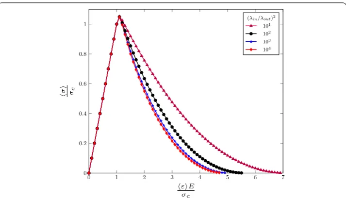
Fig. 4 Effect of the interface condition at the edges of the interphase on the global stress–strain response
bulk drops systematically for higher contrasts. The maximum contrast that the numerical solver for the damage equation could handle was (λin/λout)2=104. For this contrast, we observe that the zone of spread of interphase damage into the bulk has reduced to less than 0.2l.
Figure3also shows that for high contrast ratios, the non-uniformity ofφnlcaused by the imperfection decreases and the damage profile becomes increasingly uniform inside the band. Consistent with Eq. (18), the slope ofφnlat the two edges of the interphase tends to zero as the length scale contrast is increased. For the lower ratios, the interaction with the undamaged region next to the band results in a slower evolution ofφnlnear the edge of the band compared to its centre.
The effect of this slowing down is observable in the averaged stress–strain response, see Fig.4. As a result of it, the initial softening slope is less steep. This in turn results in an over-prediction of the amount of dissipation during the damage process as compared with that for the cases with a sufficient contrast, i.e. (λin/λout)2=103–104.
Figure 5(left) shows the calculated fracture energy Gn
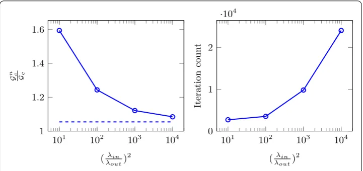
c relative to the one predicted by Eq. (14). Remember that Gc was derived for the rate-independent limit. Hence, we should expect the rate-dependent, computedGcnto approachGc, but not necessarily to asymptote to it. A much closer approximation of the rate dependent ideal solution (dashed curve) can be expected, as it captures the additional dissipation due to rate effects. Indeed, the ratioGcn/Gcdrops to less than 1.1 for the highest length scale contrast applied. This higher accuracy however entails significantly more iterations (Fig.5(right)) required to solve Eq. (23): this number goes up by a factor of 10 as the contrast is increased from
(λin/λout)2=101to 104. This is essentially due to thed(λ
2d dx)
101 102 103 104
1 1.2 1.4 1.6
(λin λout)
2
G
n c Gc
101 102 103 104
0 1 2
·104
(λin λout)
2
Iteration
coun
t
Fig. 5 The reduction of fracture energy error (left) and increase in linear iterations (right) as a function of length scale contrast
Comparison of gradient and integral nonlocal damage models
The analysis in “Analytical solution for the rate-independent case” section showed that for a uniform damage strain distribution in the rate-independent limit, choosingεf according to Eq. (15), a constant fracture energy can be obtained, irrespective of the interphase band thicknessl. In this section, we want to test the same hypothesis but in a numerical setting, where localisation is triggered by the presence of an imperfection (as discussed above). This is a test of the effectiveness of the two types of nonlocality in regularizing the damage (and damage strain rates) and thus facilitating the use of simple scaling Eq. (15) for the interphase band.
Different interphase band thicknesses (l/L=0.010,0.015,0.020,0.025,0.030) are stud-ied. ˙εd0 = 1.0 s−1 and εf = 5 ×10⁻⁵L/l in combination with the parameters in “Model parameters used” section are used. For both models, three different values of the nonlocal length scale are used:λ/l=0.5,1.0,and 1.5, where for the gradient damage based approach λin = λ andλout is varied such that a constant length scale contrast (λin/λout)2=104is obtained.
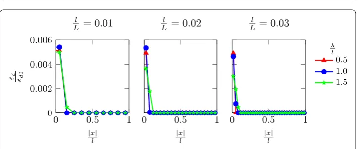
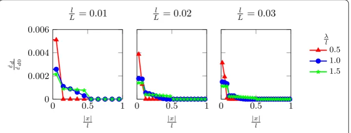
Figures6and7show the damage profiles obtained towards the end of the damage process for the gradient and integral model, respectively. The damage distribution obtained for the gradient damage model, shown in Fig.6, is increasingly uniform inside the interphase band as the length scaleλis increased, for all the band thicknessesl. However, a slight gradient remains even for λ/l = 1.5. This is due to the imperfect insulation of the interphase damage from the surrounding (undamaged) bulk, as discussed in “Effect of length scale contrast in the gradient based model” section. The integral nonlocal model, in Fig. 7, shows a nearly constant damage inside the band forλ/l≥ 1.0—again for alll/L. For the smallest length scale considered,λ/l = 0.5, some of the non-uniformity introduced by the imperfection remains.
0 0.5 1 0
0.25 0.5 0.75 1
|x|
l
φnl
l
L
= 0
.
01
0 0.5 1
|x|
l l
L
= 0
.
02
0 0.5 1
|x|
l l
L
= 0
.
03
λ l
0.5 1.0 1.5
Fig. 6 Nonlocal damageφnldistribution atεσcE =4 of the gradient damage model for different interphase thicknesses and nonlocal length scales
0 0.5 1
0 0.25 0.5 0.75 1
|x|
l
φnl
l
L
= 0
.
01
0 0.5 1
|x|
l l
L
= 0
.
02
0 0.5 1
|x|
l l
L
= 0
.
03
λ l
0.5 1.0 1.5
Fig. 7 Nonlocal damageφnldistribution atεσE
c =4 of the integral averaging damage model for different interphase thicknesses and nonlocal length scales
0 0.5 1
0 0.002 0.004 0.006
|x|
l
˙
εd ˙
εd0
l
L
= 0
.
01
0 0.5 1
|x|
l l
L
= 0
.
02
0 0.5 1
|x|
l l
L
= 0
.
03
λ l
0.5 1.0 1.5
Fig. 8 Normalised damage opening rates distribution atεσE
c =4 of the gradient damage model for different interphase thicknesses and nonlocal length scales
model it is also milder for the larger values ofλ/landl/Lconsidered, indicating that the nonlocal averaging is more effective for a large nonlocal length scaleλ. In the gradient model a significant degree of localisation remains, even for the largestλconsidered, i.e
λ/l=1.5.
0 0.5 1 0
0.002 0.004 0.006
|x|
l
˙
εd
˙
εd0
l
L = 0.01
0 0.5 1
|x|
l
l
L = 0.02
0 0.5 1
|x|
l
l
L = 0.03
λ l
0.5 1.0 1.5
Fig. 9 Normalised damage opening rates distribution atεσE
c =4 of the integral averaging model for different interphase thicknesses and nonlocal length scales
0 2 4 6
0 0.5 1
σc
σ σc
l L = 0.01
0 2 4 6
σc
l L = 0.02
0 2 4 6
σc
l L = 0.03
λ l
0.5
1.0
1.5
Rate indep.
E
ε εE εE
Fig. 10 The overall stress-strain response of the gradient damage model for different interphase band thicknesses and nonlocal length scales
the applied average strain ¯εfor all cases considered. Also shown (in black) is the underlying rate-independent response as given (analytically) by Eq. (12). For both types of nonlocality, and for alll/Lshown, the computed stress-average strain responses forl/L=1.0 and 1.5 practically coincide. They furthermore deviate only slightly from the analytical solution. This shows that for these values of the nonlocal length scale both regularisation approaches are effective in rendering the global response objective with respect to the interphase band thickness, despite the non-uniformity observed inφnl (Figs.6,7) and, particularly, the damage strain rate (Figs.8,9). The smallest value ofλ,λ=0.5l, clearly is insufficient, as the softening responses computed for it are systematically steeper than for larger values (and than the analytical solution).
0 2 4 6 0
0.5 1
E σc
σ σc
l L = 0.01
0 2 4 6
σc
l L = 0.02
0 2 4 6
σc
l L = 0.03
λ l
0.5
1.0
1.5
Rate indep.
ε εE εE
Fig. 11 The overall stress-strain response of the integral averaging model for different interphase band thicknesses and nonlocal length scales
0.01 0.02 0.03
0.8 0.9 1 1.1 1.2
l L
G
n c Gc
Gradient damage model
λ
l 0.5 1.0 1.5 Rate dep.
0.01 0.02 0.03
l L
Integral model
Fig. 12 Performance of the fracture energy calculationGnc/Gcfor different interphase band thicknesses and nonlocal length scales
The fracture energy computed by the gradient damage approach show a discrepancy with both reference values (i.e. rate-independent and rate-dependent) on the order of 10%. Forλ/l = 0.5, the fracture energy is under-estimated, whereas the larger values of
λresult in an over-estimation. In each of these cases, the deviation furthermore varies withl/L. The integral nonlocal model performs much better. Forλ/l = 0.5, which we already observed to be too small to obtain a uniform damage in Fig.7, it under-estimates
Gc by up to 10% (Fig. 12). But for λ/l ≥ 1.0, it over-estimatesGc by≤ 5%, in a way which is consistent with the rate-dependent reference solution: the difference between the regularised solutions for λ/l = 1.0 and 1.5 and the piecewise constant reference solution is less than 1%. For practical purposes, this is more than satisfactory and the slight trend withl/L, due to the rate-sensitivity, should also pose no problem.
Conclusion and outlook
and performance of integral and gradient damage based nonlocal averaging methods have been discussed.
For the gradient damage approach, it was found that the mechanical response and dissipation depends on the accuracy with which the flux boundary condition at the edges of the interphase domain can be enforced. In order to restrict the damage to the interphase only, a flux free condition at the interphase boundaries was used. Since FFT solvers do not allow solving an equation on an irregular domain, in the gradient approach, a contrast in the nonlocal length scale was used to approximate the flux free boundary condition at the interphase edges. The error in the fracture energy reduces upon increasing this length scale contrast. However, a high contrast renders the gradient based approach highly heterogeneous and entails numerical problems.
The implementation of the integral approach on the other hand was straightforward and effective. It only requires storage of the nonlocal weights in a matrix that can be opti-mized using sparse storage. Regularisation length scale values equal to or greater than the interphase band thickness were found to give accurate predictions for the fracture energy, largely independent of the (arbitrary) interphase band thicknessl. The slight (≤ 1%) vari-ation which remains is due to the fact that the scaling of εf according to Eq. (15) does not take into account the strain rate sensitivity of the damage model. From the current study it is very clear that integral approach offers more advantage from the computa-tional efficiency point of view. We expect the same advantages to carry over in mul-tidimensional cases on periodic microstructures. Nevertheless, this still remains to be tested.
We wish to emphasize that, although it enables a rigorous and transparent comparison, the 1D problem considered here may not reveal all complexities that could be encoun-tered in two or three dimensions. For instance, care should be taken that the nonlocality introduced to homogenise the damage across the interphase band thickness does not affect the propagation of damage along the band in an unrealistic manner. One possible way to avoid this is by introducing anisotropy in the nonlocal averaging. In the gradient damage approach this can be achieved by having a tensorial form for the nonlocal length scale, while for the integral approach an orientation dependent averaging kernel can be used. Modelling decohesion of polycrystalline interfaces will require a proper treatment of triple junctions to avoid the issue of non-unique interface normals. Furthermore, a method to couple interface damage with the bulk damage in voxel based models [28] can also be explored to model more complex crack patterns—kinking and branching of cracks into the bulk. These issues are currently under investigation and will comprise future works.
Abbreviations
FFT: fast Fourier transform; FE: finite element; FEM: finite element method; TSL: traction separation law.
Authors’ contributions
Author details
1Department of Mechanical Engineering, Eindhoven University of Technology, P.O. Box 513, 5600 MB Eindhoven, The
Netherlands,2Microstructure Physics and Alloy Design, Max-Planck Institut für Eisenforschung, Max-Planck-Str. 1, 40237
Düsseldorf, Germany.
Acknowledgements
The authors would like to acknowledge the fruitful discussions with Prof. Bob Svendsen of RWTH Aachen University and Max Planck Institut für Eisenforschung, Düsseldorf, Germany. The work presented is part of the research done under the project S22.2.1349b in the framework of the research program Materials innovation institute M2i.
Competing interests
The authors declare that they have no competing interests.
Availability of data and materials
Not applicable.
Consent for publication
Not applicable.
Ethics approval and consent to participate
Not applicable.
Funding
This research is supported by Tata Steel Europe through the Materials innovation institute (M2i) and Netherlands Organisation for Scientific Research (NWO), under the grant number STW 13358.
Publisher’s Note
Springer Nature remains neutral with regard to jurisdictional claims in published maps and institutional affiliations.
Received: 20 December 2017 Accepted: 20 March 2018
References
1. Moulinec H, Suquet P. A numerical method for computing the overall response of nonlinear composites with complex microstructure. Comput Methods Appl Mech Eng. 1998;157(1–2):69–94.
2. Lebensohn RA, Kanjarla AK, Eisenlohr P. An elasto-viscoplastic formulation based on fast Fourier transforms for the prediction of micromechanical fields in polycrystalline materials. Int J Plast. 2012;32–33:59–69.
3. Eisenlohr P, Diehl M, Lebensohn RA, Roters F. A spectral method solution to crystal elasto-viscoplasticity at finite strains. Int J Plast. 2013;46:37–53.
4. Roters F, Eisenlohr P, Hantcherli L, Tjahjanto DD, Bieler TR, Raabe D. Overview of constitutive laws, kinematics, homogenization and multiscale methods in crystal plasticity finite-element modeling: theory, experiments, applications. Acta Mater. 2010;58(4):1152–211.
5. Shanthraj P, Eisenlohr P, Diehl M, Roters F. Numerically robust spectral methods for crystal plasticity simulations of heterogeneous materials. Int J Plast. 2015;66:31–45.
6. Zeman J, de Geus TWJ, Vondˇrejc J, Peerlings RHJ, Geers MGD. A finite element perspective on nonlinear FFT-based micromechanical simulations. Int J Numer Methods Eng. 2017;111(10):903–26.
7. de Geus TWJ, Vondˇrejc J, Zeman J, Peerlings RHJ, Geers MGD. Finite strain FFT-based non-linear solvers made simple. Comput Methods Appl Mech Eng. 2017;318:412–30.
8. Lebensohn RA, Needleman A. Numerical implementation of non-local polycrystal plasticity using fast fourier transforms. J Mech Phys Solids. 2016;97:333–51.
9. Vidyasagar A, Tan WL, Kochmann DM. Predicting the effective response of bulk polycrystalline ferroelectric ceramics via improved spectral phase field methods. J Mech Phys Solids. 2017;106:133–51.
10. Boeff M, Gutknecht F, Engels PS, Ma A, Hartmaier A. Formulation of nonlocal damage models based on spectral methods for application to complex microstructures. Eng Fract Mech. 2015;147:373–87.
11. Archie F, Li X, Zaefferer S. Micro-damage initiation in ferrite-martensite DP microstructures: a statistical characterization of crystallographic and chemical parameters. Mater Sci Eng A. 2017;701(February):302–13. 12. Xu XP, Needleman A. Void nucleation by inclusion debonding in a crystal matrix. Model Simul Mater Sci Eng.
1993;1(2):111.
13. Remmers JJC, de Borst R, Verhoosel CV, Needleman A. The cohesive band model: a cohesive surface formulation with stress triaxiality. Int J Fract. 2013;181(2):177–88.
14. Merkert D, Andrä H, Kabel M, Schneider M, Simeon B. Voxel-based fast solution of the Lippmann–Schwinger equation with smooth material interfaces. PAMM. 2014;14(1):579–80.
15. Hsueh-Hung Fu, Benson DJ, Meyers MA. Computational description of nanocrystalline deformation based on crystal plasticity. Acta Mater. 2004;52(15):4413–25.
16. Clayton JD, Knap J. Phase field modeling of directional fracture in anisotropic polycrystals. Comput Mater Sci. 2015;98:158–69.
18. de Borst R, Carmeliet J, Pamin J, Sluys LJ. Some future directions in computational failure mechanics. In: DIANA computational mechanics’ 94; proceedings of the 1st international DIANA conference. Dordrecht: Kluwer Academic Publishers; 1994. p. 1–12.
19. Peerlings RHJ, de Borst R, Brekelmans WAM, de Vree JHP. Gradient enhanced damage for quasi-brittle materials. Int J Numer Methods Eng. 1996;39(19):3391–403.
20. Geers MGD. Finite strain logarithmic hyperelasto-plasticity with softening: a strongly non-local implicit gradient framework. Comput Methods Appl Mech Eng. 2004;193(30):3377–401.
21. Shanthraj P, Svendsen B, Sharma L, Roters F, Raabe D. Elasto-viscoplastic phase field modelling of anisotropic cleavage fracture. J Mech Phys Solids. 2017;99(99):19–34.
22. Moës N, Stolz C, Chevaugeon N. Coupling local and non-local damage evolutions with the thick level set model. Adv Model Simul Eng Sci. 2014;1(1):16.
23. Shanthraj P, Sharma L, Svendsen B, Roters F, Raabe D. A phase field model for damage in elasto-viscoplastic materials. Comput Methods Appl Mech Eng. 2016;312:167–85.
24. Poh LH, Sun G. Localizing gradient damage model with decreasing interactions. Int J Numer Methods Eng. 2017;110(6):503–22.
25. Balay S, Abhyankar S, Adams M, Brune P, Buschelman K, Dalcin L, Gropp W, Smith B, Karpeyev D, Kaushik D, et al. Petsc users manual revision 3.7. Technical report, Argonne National Lab. (ANL), Argonne, IL (United States). 2016. 26. Willot F. Fourier-based schemes for computing the mechanical response of composites with accurate local fields.
Comptes Rendus Mécanique. 2015;343(3):232–45.
27. Peerlings RHJ, Geers MGD, de Borst R, Brekelmans WAM. A critical comparison of nonlocal and gradient-enhanced softening continua. Int J Solids Struct. 2001;38(44–45):7723–46.