623 Information Technology and Control 2018/4/47
A Method for Reverse
Engineering UML Use Case
Model for Websites
ITC 4/47
Journal of Information Technology and Control
Vol. 47 / No. 4 / 2018 pp. 623-638
DOI 10.5755/j01.itc.47.4.21264
A Method for Reverse Engineering UML Use Case Model for Websites
Received 2018/07/17 Accepted after revision 2018/09/27
http://dx.doi.org/10.5755/j01.itc.47.4.21264
Corresponding author: [email protected]
Lina Čeponienė, Vaidotas Drungilas, Mantas Jurgelaitis, Jonas Čeponis
Faculty of Informatics; Kaunas University of Technology; Studentų Str. 50, LT-51368, Kaunas, Lithuania; e-mails: [email protected], [email protected], [email protected], [email protected]Problems with inadequately documented or undocumented websites could be alleviated by introducing reverse engineering of UML diagrams. In this paper, the method for reverse engineering UML use case model for websites is presented. It consists of two steps: recording user actions in the analyzed website, and then transforming the combination of recorded activity and publicly available HTML code information into UML use case model. This model consists of UML use case diagram and UML activity diagrams describing scenario of each use case. The proposed method is implemented as a Google Chrome plugin named WEB2UML. WEB2UML is able to generate UML use case and activity diagrams in XMI format, compatible with MagicDraw UML CASE tool. During experi-mental evaluation of the WEB2UML tool, two UML use case models were reverse engineered: one for moodle. if.ktu.lt website and another for researchgate.net website. The quality of generated models was evaluated using an anonymous questionnaire completed by 13 UML modelling experts. The results of expert evaluation are encouraging: in total, average expert evaluation score was 8,4 in a scale of ten.
KEYWORDS: UML, use case diagram, activity diagram, reverse engineering, website.
1. Introduction
UML is a commonly used modelling language encom-passing a wide range of various diagrams for specifying different aspects of software systems. UML use case di-agrams are used for expressing user requirements [15, 30]. Use case diagram supplemented by descriptions for each use case forms use case model of the system. Use case description contains a scenario, which can be
develop-Information Technology and Control 2018/4/47 624
ers, because it helps to represent the system in terms of its functional usage [10].
Model Driven Engineering (MDE) [28] is an approach which strives to improve software development pro-cesses by introducing modelling into different steps of the process, such as implementation, testing, main-tenance, etc. MDE employs UML models for repre-senting complex systems and proposes transforma-tions for software development. Apart from utilizing the potential of model transformations, MDE em-phasizes the fact that modeling can help to decrease the complexity of software development tasks, as the models can be used to represent the analyzed system in different levels of abstraction [7].
However, problems of keeping UML models up to date arise, as updating the diagrams requires additional ef-fort from developers. Websites more often than any other type of software are subject to constant updates and improvements, as they have to meet ever chang-ing user requirements and succeed in highly com-petitive market [17, 21]. Website developers, facing continuous changes in requirements, tend to sacrifice the quality of website documentation and spend more resources on development of new website function-ality [26]. If not properly maintained, UML models lose their practical value and can even be misleading. Finding and fixing the discrepancies between docu-mented UML models and the present functionality of a web system, requires significant effort from de-velopment team. Likewise, the support of legacy sys-tems, whose documentation is not available, is also a challenging task [14].
The problems with inadequately documented or un-documented systems can be alleviated by introducing reverse engineering of UML models. Reverse engineer-ing is defined as a process of system analysis performed in order to identify the systems structure and behavior and represent them in a different form or using a higher level of abstraction [5]. Model Driven Engineering prin-ciples can be successfully applied in reverse engineering area: Model Driven Reverse Engineering (MDRE) con-centrates on applying MDE strategies for developing efficient reverse engineering solutions [4]. Reverse en-gineered UML diagrams can help to visualize, improve understanding and provide documentation for the exist-ing functionality of web systems [27, 32].
In this paper, a method for reverse engineering UML use case model from web systems is presented. This method enables transformation of recorded website
user activity into UML use case and activity diagrams. The method consists of two main steps: recording user actions in the website, and then transforming the combination of recorded activity and HTML code information into UML use case model.
Our method is based on dynamic analysis of website usage, without analyzing the internal source code. Only directly accessible HTML code of website is an-alyzed together with the recorded user activity. Many existing methods for reverse engineering UML dia-grams require access to the source code of system un-der analysis [2, 6, 9, 16]. Reverse engineering UML di-agrams from websites without access to source code can be useful in various situations, e.g. during analy-sis of undocumented legacy systems for finding out their functionality or for comparing functionality of existing public websites [1]. Furthermore, reverse en-gineering UML diagrams excluding analysis of source code ensures that our approach is language indepen-dent, which broadens the set of web applications that can be reverse engineered using our method. Other methods, not relying on source code analysis exist, but these methods mainly generate UML sequence, state diagrams [13, 33] or non-UML based visualizations [18] for websites. None of the aforementioned meth-ods generates both use case and activity diagrams. Our approach also employs real web application us-ers – they can perform their usual activities in web-site, just providing information about their role and performed processes, and the tool records these ac-tivities for further transformation into UML use case and activity diagrams. A Google Chrome plugin as a prototype tool was implemented for evaluating the proposed method. Experiment results indicate that the tool is capable of reversing use case models for websites. Although there still are some disadvantag-es in method implementation, such as action naming problems in activity diagrams, experts evaluated the quality of generated models as adequate.
625 Information Technology and Control 2018/4/47
2. Related Work
Reverse engineering can facilitate comprehension and decrease effort required for website mainte-nance, reengineering or evolution [5]. UML-based reverse engineering is quite popular as UML is com-monly used as a standard for software modelling and as a tool for communication [27]. UML diagrams pro-vide a clear notation, which can be used to construct diagrams for various aspects of systems. Reverse en-gineering of UML diagrams can be useful for improv-ing understandimprov-ing of program code in various areas of software development even in software development education [32]. UML diagrams are suitable for spec-ifying system structural elements and behavior at various abstraction levels [24]. Structural UML dia-grams, such as class, component or package diagrams can be used to represent static structures in terms of system parts and their relations. Furthermore, behav-ioral diagrams, such as activity, use case or sequence diagrams, are able to express dynamic behavior of ob-jects in the analyzed system.
Reverse engineering methods cover both structural and behavioral UML diagrams, but in general, static structures can be reverse engineered with less dif-ficulty than behavioral diagrams. A number of UML CASE tools, for example MagicDraw [23] and Visual Paradigm [31], already support reverse engineering of structural UML diagrams, such as class diagrams [25]. Although CASE tools provide similar function-ality, a need for more effective ways of reverse engi-neering structural diagrams still exists. For example, in [8] a method for reverse engineering class diagrams is presented, which is more effective and flexible in terms of scalability than reverse engineering options in existing CASE tools. This method uses a set of ac-curate mappings for representing C++ syntactic and semantic information in UML class diagrams.
In contrast, reverse engineering behavioral diagrams is a more complicated task, not so widely supported by UML CASE tools. Sequence diagrams can be re-verse engineered in several UML CASE tools, such as Enterprise Architect [29], but the implementation of this feature is quite primitive [25]. Quite a lot of stud-ies analyze the possibilitstud-ies for reverse engineering sequence diagrams, such as [2, 9, 13, 33]. Reversing other behavioral diagrams, like activity diagrams, use case diagrams and state machines is not supported by
CASE tools, although there is also a number of studies in this area [11, 13, 19].
There are several solutions focusing on reverse engi-neering of behavioral UML diagrams, particularly for websites. The reverse engineering tool PHP2XMI [2] is able to generate behavioral model of a website, ex-pressed as an UML sequence diagram. The tool anal-yses PHP-based web applications’ source code for in-serting probes to collect dynamic information, stores and filters execution traces generated by the probes during interactive browser sessions and transforms re-corded execution traces into UML sequence diagrams. Another website-oriented approach is presented in [9]. In this approach, a tool named WARE is proposed for website reverse engineering of UML use case, se-quence and class diagrams. WARE tool uses static code as an input and is capable of reverse engineering only when having access to entire source code of web application. In general, when source code is available, reverse engineering UML diagrams seems to have more possibilities for implementation, as source code is a valuable source of information [2, 6, 9, 16]. Unfor-tunately, the source code is not always available. In addition, analysis of application without examining source code ensures that our method is language in-dependent. It is also important for analysis of a wide range of websites implemented using different tech-nologies. Our research concentrates on reverse engi-neering websites without access to internal source code and utilizing only information acquired from publicly available HTML code and recorded user ac-tivity in the website.
Information Technology and Control 2018/4/47 626
method is intended for (re)documenting API usage and uses trace information, gathered by monitoring behavior of applications, which are using the API. Af-terwards, UML state machine and sequence diagrams are reverse engineered from the gathered informa-tion. The problems of merging the recorded execution traces are addressed in [22], where a method for iden-tifying systems key behavior and generating a read-able sequence diagrams is presented.
There are several studies on reverse engineering spe-cifically use case diagrams. Some of them are based on source code analysis [6, 9, 16], which is not applicable to our method. Others have one major disadvantage: they require effort for creating additional specifications which are used as an input for diagram generation. In [11], reverse engineering is used for generating use case models from structured textual use case specifications. In [19], event tables are used for use case model genera-tion. In event tables, information about each event, the source of event, action and associated object must be provided for generating informative use case model. In our work, we decided to minimize required additional input, as requirement for exhaustive additional spec-ifications compromises the whole idea of simplifying diagram extraction process.
Reverse engineering approaches, using different form of visualization (e.g. [18, 20]) than UML-based approaches, provide further insight. In [18] the ap-proach for visualization of web-based systems user interface is proposed. User interface models, which use information visualization technique ModelUIVIZ, are reverse engineered from web applications. The tool for this approach, WMUID, was implemented as a Google Chrome plugin, which uses Google Chrome API to access website elements. Both crawler and tracer mechanisms are used for data extraction. The crawler analyses user interface and identifies interac-tive elements, such as buttons, inputs and links. The tracer monitors and registers user interaction and navigation. Another tool, WMUIT, is used for display-ing the data collected by WMUID tool. In our work, a tool similar to the tracer is also implemented as a Chrome plugin. In general, the principles of [18] are successfully applied in our research.
Our proposed method analyses information acquired by recording website usage. It does not require access to the websites source code to perform static code analysis, as dynamic analysis is enough for gather-ing required information. The only additional infor-mation source for our reverse engineering method
is publicly available website HTML code. Based on other methods’ implementations, we decided to im-plement usage recording tool as a browser plugin for gathering event sequences, which can then be con-verted to use case and activity diagrams.
3. A Method for Reverse Engineering
UML Use Case Model
The proposed method for reverse engineering UML use case model enables dynamic analysis of web ap-plications, in order to generate UML use case model. The method does not require access to internal source code of the application – only recorded user actions and public HTML content is used. The created use
Figure 1
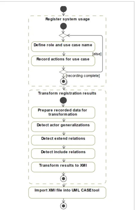
General process for reverse engineering of UML use case model
The first step of the method is to record user actions in the website under analysis. The user indicates his role and process (use case) he is going to perform in the analyzed website. Afterwards, user performs actions in the website for particular process and the tool logs the events’ sequences. When the user indicates, that he has recorded actions for all required usage scenarios of the website, the second step can be performed. Initially, website usage recording results are prepared for transformation by removing actors’ and use cases’ duplicates. Afterwards, registered event sequences are combined and various types of appropriate relations between actors and use cases are detected, such as generalizations between actors, include and
extend relations between use cases, associations between actors and use cases. The results are then transformed into an XMI file which can be imported in UML CASE tool for further usage.
4. Algorithms for Relation Detection
In this paper, we present in detail three most important algorithms of our method – actor generalization detection, extend relation detection, and include relation detection. These algorithms make up the main group of procedures required for transforming recorded user activity into UML diagrams. The algorithms are performed sequentially, as defined in Figure 1.
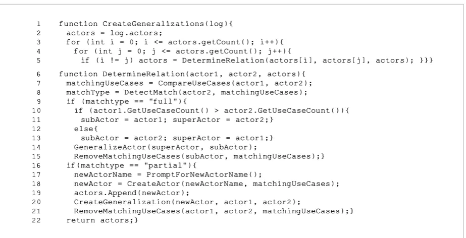
The first algorithm (Figure 2) detects generalization relations between actors in use case diagram by analyzing recorded data associated with user defined roles. The roles that user specifies during activity recording are recognized as actors in our method. Each actor has a set of recorded processes, which are identified as use cases associated with this actor. The actors owned use case sets are compared, and two types of match can be detected (Figure 2, line 8): full or partial. A full match between use case sets is detected when intersection between two actors use case sets is equal to use case set of one of these actors. In that case, we have to determine subactor (actor who has more use cases) and superactor (which has less use cases) for creating generalization (Figure 2, lines 10-14), and then remove all of
subactors’ inherited and now redundant use cases from his set (Figure 2, line 15). Another type of match between use case sets is a partial match. Partial match occurs when intersection between actors use case sets is not empty and is not equal to use case set of one of the actors. Then our algorithm creates a new actor, which will generalize both compared actors, and prompts for a new actor name (Figure 2, lines 17-18). Use cases from the intersection of compared actor sets are associated with the new actor (Figure 2, line 19). Afterwards, a generalization is created between new actor and each of the compared actors (Figure 2, line 20). Lastly, the redundant inherited use cases are removed from compared actors sets (line 21). The comparison of use case sets is repeated until all actors are compared to each other, including the ones created during the generalization creation.
Figure 2
627 Information Technology and Control 2018/4/47
case model encompasses UML use case diagram along with specifications of each use case in a form of UML activity diagrams. Each activity diagram specifies a use case scenario with required include and extend re-lations between use cases. Alternative scenarios are also represented in activity diagrams, as the method is able to combine recorded scenarios for appropriate use cases. In reverse engineered use case diagram, generalizations between actors are also determined and additional actors may be created if situations arise when use case sets are overlapping. The method consists of two main steps, after which the generated UML diagrams can be imported, viewed and edited in UML CASE tool (Figure 1).
The first step of the method is to record user actions in the website under analysis. The user indicates his role and process (use case) he is going to perform in the analyzed website. Afterwards, user performs actions in the website for particular process and the tool logs the events’ sequences. When the user indicates, that he has recorded actions for all required usage scenar-ios of the website, the second step can be performed. Initially, website usage recording results are prepared for transformation by removing actors’ and use cases’ duplicates. Afterwards, registered event sequences are combined and various types of appropriate
rela-tions between actors and use cases are detected, such as generalizations between actors, include and extend relations between use cases, associations between ac-tors and use cases. The results are then transformed into an XMI file which can be imported in UML CASE tool for further usage.
4. Algorithms for Relation Detection
In this paper, we present in detail three most important algorithms of our method – actor generalization detec-tion, extend relation detecdetec-tion, and include relation de-tection. These algorithms make up the main group of procedures required for transforming recorded user activity into UML diagrams. The algorithms are per-formed sequentially, as defined in Figure 1.
The first algorithm (Figure 2) detects generalization relations between actors in use case diagram by ana-lyzing recorded data associated with user defined roles. The roles that user specifies during activity recording are recognized as actors in our method. Each actor has a set of recorded processes, which are identified as use cases associated with this actor. The actors owned use case sets are compared, and two types of match can be detected (Figure 2, line 8): full or partial. A full match
The second algorithm detects extend relations between use cases in use case diagram. It is worth mentioning that both include and extend use case relations must also be represented in activity diagrams. For each include relation between including and included use case, there must exist a reference (in the form of callBehaviorAction) in including use cases’ activity diagram. Analogously, for each extend relation between extended and extending use case, in extended use cases’ activity diagram, there must exist a decision node (representing the choice of performing the extending use cases activity diagram), a reference (in the form of callBehaviorAction), and a merge node.
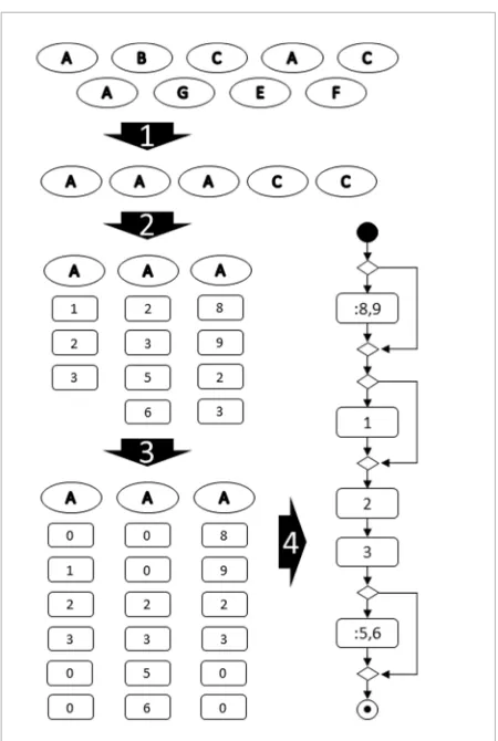
General process of extend relation detection is presented in Figure 3, where main steps of the process are marked as arrows and numbered. The pool of user defined processes recorded during website usage (recognized as use cases) is analyzed.
Figure 3
Main steps of extend relation detection
In the first step, use cases with repeated names are selected. As a result of the first step, subsets are created for each group of same named use cases. In the second step, one use case subset is selected for further analysis. During the third step, the sequences of recorded actions are compared by finding matching subsequences. The sets are modified in such a way, that matching sequences are positioned along the same indexes, and placeholder variables (“0” in Figure 3) are appended at the beginning and the end of the sequences for alignment. An example of
1 function CreateGeneralizations(log){ 2 actors = log.actors;
3 for (int i = 0; i <= actors.getCount(); i++){ 4 for (int j = 0; j <= actors.getCount(); j++){
5 if (i != j) actors = DetermineRelation(actors[i], actors[j], actors); }}} 6 function DetermineRelation(actor1, actor2, actors){
7 matchingUseCases = CompareUseCases(actor1, actor2); 8 matchType = DetectMatch(actor2, matchingUseCases); 9 if (matchtype == "full"){
10 if (actor1.GetUseCaseCount() > actor2.GetUseCaseCount()){ 11 subActor = actor1; superActor = actor2;}
12 else{
13 subActor = actor2; superActor = actor1;} 14 GeneralizeActor(superActor, subActor);
15 RemoveMatchingUseCases(subActor, matchingUseCases);} 16 if(matchtype == "partial"){
17 newActorName = PromptForNewActorName();
18 newActor = CreateActor(newActorName, matchingUseCases); 19 actors.Append(newActor);
20 CreateGeneralization(newActor, actor1, actor2);
21 RemoveMatchingUseCases(actor1, actor2, matchingUseCases);} 22 return actors;}
Figure 2
Information Technology and Control 2018/4/47 628
between use case sets is detected when intersection between two actors use case sets is equal to use case set of one of these actors. In that case, we have to de-termine subactor (actor who has more use cases) and superactor (which has less use cases) for creating gen-eralization (Figure 2, lines 10-14), and then remove all
of subactors’ inherited and now redundant use cases
from his set (Figure 2, line 15). Another type of match between use case sets is a partial match. Partial match occurs when intersection between actors use case sets is not empty and is not equal to use case set of one of the actors. Then our algorithm creates a new actor, which will generalize both compared actors, and prompts for a new actor name (Figure 2, lines 17-18). Use cases from the intersection of compared actor sets are associated with the new actor (Figure 2, line 19). Afterwards, a generalization is created between new actor and each of the compared actors (Figure 2, line 20). Lastly, the redundant inherited use cases are removed from com-pared actors sets (line 21). The comparison of use case sets is repeated until all actors are compared to each other, including the ones created during the general-ization creation.
The second algorithm detects extend relations be-tween use cases in use case diagram. It is worth men-tioning that both include and extend use case relations must also be represented in activity diagrams. For each include relation between including and included use case, there must exist a reference (in the form of callBehaviorAction) in including use cases’ activity diagram. Analogously, for each extend relation be-tween extended and extending use case, in extended use cases’ activity diagram, there must exist a deci-sion node (representing the choice of performing the extending use cases activity diagram), a reference (in the form of callBehaviorAction), and a merge node. General process of extend relation detection is pre-sented in Figure 3, where main steps of the process are marked as arrows and numbered. The pool of user defined processes recorded during website usage (recognized as use cases) is analyzed.
In the first step, use cases with repeated names are selected. As a result of the first step, subsets are cre-ated for each group of same named use cases. In the second step, one use case subset is selected for fur-ther analysis. During the third step, the sequences of recorded actions are compared by finding matching subsequences. The sets are modified in such a way,
that matching sequences are positioned along the same indexes, and placeholder variables (“0” in Fig-ure 3) are appended at the beginning and the end of the sequences for alignment. An example of aligned sequences is presented in Figure 3 as a result of the third step. Matching sequence in this case consists of recorded actions 2 and 3.
In the fourth step, the new use case combining all subset use cases is created and its activity diagram is gradually generated. The required elements (e.g. actions, decision and merge nodes) are gradually ap-pended to activity diagram and joined with control flow relations. To determine the order of appending elements, matching sequences of actions are detect-ed. Each action of subsets’ use case is processed de-pending on whether it exists in a range of matching elements or not. When the action exists in the range of matching actions, and we have reached the appro-Figure 3
Main steps of extend relation detection
The second algorithm detects extend relations between use cases in use case diagram. It is worth mentioning that both include and extend use case relations must also be represented in activity diagrams. For each include relation between including and included use case, there must exist a reference (in the form of callBehaviorAction) in including use cases’ activity diagram. Analogously, for each extend relation between extended and extending use case, in extended use cases’ activity diagram, there must exist a decision node (representing the choice of performing the extending use cases activity diagram), a reference (in the form of callBehaviorAction), and a merge node.
General process of extend relation detection is presented in Figure 3, where main steps of the process are marked as arrows and numbered. The pool of user defined processes recorded during website usage (recognized as use cases) is analyzed.
Figure 3
Main steps of extend relation detection
In the first step, use cases with repeated names are selected. As a result of the first step, subsets are created for each group of same named use cases. In the second step, one use case subset is selected for further analysis. During the third step, the sequences of recorded actions are compared by finding matching subsequences. The sets are modified in such a way, that matching sequences are positioned along the same indexes, and placeholder variables (“0” in Figure 3) are appended at the beginning and the end of the sequences for alignment. An example of
1 function CreateGeneralizations(log){ 2 actors = log.actors;
3 for (int i = 0; i <= actors.getCount(); i++){ 4 for (int j = 0; j <= actors.getCount(); j++){
5 if (i != j) actors = DetermineRelation(actors[i], actors[j], actors); }}} 6 function DetermineRelation(actor1, actor2, actors){
7 matchingUseCases = CompareUseCases(actor1, actor2); 8 matchType = DetectMatch(actor2, matchingUseCases); 9 if (matchtype == "full"){
10 if (actor1.GetUseCaseCount() > actor2.GetUseCaseCount()){ 11 subActor = actor1; superActor = actor2;}
12 else{
13 subActor = actor2; superActor = actor1;} 14 GeneralizeActor(superActor, subActor);
15 RemoveMatchingUseCases(subActor, matchingUseCases);} 16 if(matchtype == "partial"){
17 newActorName = PromptForNewActorName();
18 newActor = CreateActor(newActorName, matchingUseCases); 19 actors.Append(newActor);
20 CreateGeneralization(newActor, actor1, actor2);
629 Information Technology and Control 2018/4/47
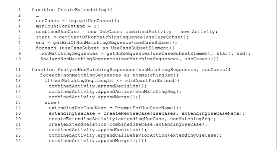
priate place during combined activity diagram cre-ation, new action element is created and appended to the activity diagram. Otherwise, actions that do not exist in matching range are included in a subsequence starting with non-matching action and ending when action in matching range is found or main sequence ends. Figure 4 presents a pseudo-code fragment demonstrating the processing of non-matching sub-sequences. If non-matching subsequence contains less actions then determined beforehand (Figure 4, line 4), its actions are appended to the activity. Deci-sion and merge nodes are inserted, respectively, be-fore and after the actions, joining them with control flow relations (Figure 4, lines 14-16). If non-matching subsequence contains more actions than the defined constant, a new use case is created. Use case name must be provided for creation (Figure 4, line 18) and activity diagram is also created for this use case. Ac-tions of non-matching sequence are inserted into the new activity diagram (Figure 4, line 20). The new ex-tending use case and combined use case are joined by extend relation (Figure 4, line 21). Combined use cas-es’ activity diagram is appended with decision node, reference (callBehaviorAction) to the new activity di-agram, and merge node (Figure 4, lines 22-24).
Figure 4
Fragment of algorithm in pseudocode for extend relation detection
The third algorithm is used for detecting include re-lations between use cases. It is started only when all extend relations are detected and all alternative se-quences are combined into respective use cases. In Figure 5, pseudocode fragment for include relation detection is presented. In the beginning, matching recorded actions’ sequences longer than the defined constant (Figure 5, line 3) are detected in all use cas-es (Figure 5, line 4). Use cascas-es are grouped in subsets where matching sequences were found (Figure 5, line 5). For each use case subset, a new use case (which will act as included use case) is created, whose name must be provided. Additionally, a new activity dia-gram for the new use case is created encompassing the matching sequence (Figure 5, line 12). The actions of matching sequence are removed from all the use cases in the subset. The new use case is then joined with the including use cases from the subset using include relation. For all subset use cases, a reference (callBehaviorAction) to the new use case is inserted instead of removed matching sequence.
The result of execution of all three presented algo-rithms is transformed into XMI format. This ensures that resulting diagrams can be modified and improved using CASE tool for further usage. The resulting XMI aligned sequences is presented in Figure 3 as a
result of the third step. Matching sequence in this case consists of recorded actions 2 and 3.
In the fourth step, the new use case combining all subset use cases is created and its activity diagram is gradually generated. The required elements (e.g. actions, decision and merge nodes) are gradually appended to activity diagram and joined with control flow relations. To determine the order of appending elements, matching sequences of actions are detected. Each action of subsets’ use case is processed depending on whether it exists in a range of matching elements or not. When the action exists in the range of matching actions, and we have reached the appropriate place during combined activity diagram creation, new action element is created and appended to the activity diagram. Otherwise, actions that do not exist in matching range are included in a subsequence starting with non-matching action and ending when action in matching range is found or main sequence ends. Figure 4 presents a pseudo-code fragment
demonstrating the processing of non-matching subsequences. If non-non-matching subsequence contains less actions then determined beforehand (Figure 4, line 4), its actions are appended to the activity. Decision and merge nodes are inserted, respectively, before and after the actions, joining them with control flow relations (Figure 4, lines 14-16). If non-matching subsequence contains more actions than the defined constant, a new use case is created. Use case name must be provided for creation (Figure 4, line 18) and activity diagram is also created for this use case. Actions of non-matching sequence are inserted into the new activity diagram (Figure 4, line 20). The new extending use case and combined use case are joined by extend relation (Figure 4, line 21). Combined use cases’ activity diagram is appended with decision node, reference (callBehaviorAction) to the new activity diagram, and merge node (Figure 4, lines 22-24).
Figure 4
Fragment of algorithm in pseudocode for extend relation detection
The third algorithm is used for detecting include relations between use cases. It is started only when all
extend relations are detected and all alternative
sequences are combined into respective use cases. In Figure 5, pseudocode fragment for include relation detection is presented. In the beginning, matching recorded actions’ sequences longer than the defined constant (Figure 5, line 3) are detected in all use cases (Figure 5, line 4). Use cases are grouped in subsets where matching sequences were found (Figure 5, line 5). For each use case subset, a new use case (which will
act as included use case) is created, whose name must be provided. Additionally, a new activity diagram for the new use case is created encompassing the matching sequence (Figure 5, line 12). The actions of matching sequence are removed from all the use cases in the subset. The new use case is then joined with the including use cases from the subset using include relation. For all subset use cases, a reference
(callBehaviorAction) to the new use case is
inserted instead of removed matching sequence. 1 function CreateExtends(log){
2 …
3 useCases = log.getUseCases(); 4 minCountForExtend = 2;
5 combinedUseCase = new UseCase; combinedActivity = new Activity; 6 start = getStartOfNonMatchingSequence(useCaseSubset);
7 end = getEndOfNonMatchingSequence(useCaseSubset); 8 foreach (useCaseSubset as UseCaseSubsetElement){
9 nonMatchingSequences = getSubSequences(useCaseSubsetElement, start, end); 10 AnalyzeNonMatchingSequences(nonMatchingSequences, useCases);}}
11 function AnalyzeNonMatchingSequences(nonMatchingSequences, useCases){ 12 foreach(nonMatchingSequences as nonMatchingSeq){
13 if(nonMatchingSeq.lenght <= minCountForExtend){ 14 combinedActivity.appendDecision();
15 combinedActivity.appendAction(nonMatchingSeq); 16 combinedActivity.appendMerge();}
17 else {
18 extendingUseCaseName = PromptForUseCaseName();
19 extendingUseCase = createNewUseCase(useCases, extendingUseCaseName); 20 createExtendingActivity(extendingUseCase, nonMatchingSeq);
21 createExtendRelation(combinedUseCase,extendingUseCase); 22 combinedActivity.appendDecision();
Information Technology and Control 2018/4/47 630
Figure 5
Algorithm in pseudocode for include relation detection
The result of execution of all three presented algorithms is transformed into XMI format. This ensures that resulting diagrams can be modified and improved using CASE tool for further usage. The resulting XMI file contains one use case diagram,
containing use cases, actors and their relation, and activity diagrams – one for each use case.
Figure 5
Algorithm in pseudocode for include relation detection
5. Implementation of Usage
Recording and Diagram
Generation Tool
For implementing the proposed method, a tool capable of recording user actions in a website, extracting HTML code information, and transforming all gathered data into UML use case model was developed. The tool WEB2UML was implemented in a form of a plugin for Google Chrome browser. The main view of WEB2UML tool user interface is presented in Figure 6.
Figure 6
The implemented WEB2UML plugin
User activity recording implementation in WEB2UML is based on the procedure, which starts with user providing the name for the role 1 function CreateIncludes(log){
2 ...
3 minCountForInclude = 2; 4 useCases = log.getUseCases();
5 matchingSequences = getMatchingSequences(minCountForInclude, useCases); 6 matchingUseCaseSets = getMatchingSets(useCases, matchingSequences); 7 modifySets(matchingUseCaseSets, matchingSequences);}
8 function modifySets(matchingUseCaseSets, matchingSequences){ 9 for (i=0; i <= matchingUseCaseSets.getCount();i++){
10 useCaseName = PromptForUseCaseName();
11 includedUseCase = createUseCase(useCaseName);
12 createIncludedActivity(includedUseCase, matchingSequences[i]); 13 matchingUseCases = matchingUseCaseSets[i];
14 for (j=0; j <= matchingUseCases.getCount();j++){
15 matchingUseCases[j].removeActions(matchingSequences[i]); 16 createIncludeRelation(includedUseCase, matchingUseCases[j]);
17 matchingUseCases[j].insertCallBehaviorAction(matchingSequences[i]);}}}
file contains one use case diagram, containing use cas-es, actors and their relation, and activity diagrams – one for each use case.
5. Implementation of Usage
Recording and Diagram
Generation Tool
For implementing the proposed method, a tool capa-ble of recording user actions in a website, extracting HTML code information, and transforming all gath-ered data into UML use case model was developed. The tool WEB2UML was implemented in a form of a plugin for Google Chrome browser. The main view of WEB2UML tool user interface is presented in Figure 6. User activity recording implementation in WEB2UML is based on the procedure, which starts with user providing the name for the role he under-takes in the web system and the process he is going to record. Afterwards, the user performs necessary actions for fulfilling the process. The process with the same name can be recorded several times, thus demonstrating all possible alternative scenarios of process execution. User can record other processes, until he is satisfied with the recorded scope. After fishing the recording, user can export the recorded in-formation in a form of JSON (Figure 7). The recorded information in JSON format can be shared between users, later exported and imported for further use.
Figure 6
The implemented WEB2UML plugin
The result of execution of all three presented algorithms is transformed into XMI format. This ensures that resulting diagrams can be modified and improved using CASE tool for further usage. The resulting XMI file contains one use case diagram,
containing use cases, actors and their relation, and activity diagrams – one for each use case.
Figure 5
Algorithm in pseudocode for include relation detection
5. Implementation of Usage
Recording and Diagram
Generation Tool
For implementing the proposed method, a tool capable of recording user actions in a website, extracting HTML code information, and transforming all gathered data into UML use case model was developed. The tool WEB2UML was implemented in a form of a plugin for Google Chrome browser. The main view of WEB2UML tool user interface is presented in Figure 6.
Figure 6
The implemented WEB2UML plugin
User activity recording implementation in WEB2UML is based on the procedure, which starts with user providing the name for the role
1 function CreateIncludes(log){ 2 ...
3 minCountForInclude = 2; 4 useCases = log.getUseCases();
5 matchingSequences = getMatchingSequences(minCountForInclude, useCases); 6 matchingUseCaseSets = getMatchingSets(useCases, matchingSequences); 7 modifySets(matchingUseCaseSets, matchingSequences);}
8 function modifySets(matchingUseCaseSets, matchingSequences){ 9 for (i=0; i <= matchingUseCaseSets.getCount();i++){
10 useCaseName = PromptForUseCaseName();
11 includedUseCase = createUseCase(useCaseName);
12 createIncludedActivity(includedUseCase, matchingSequences[i]); 13 matchingUseCases = matchingUseCaseSets[i];
14 for (j=0; j <= matchingUseCases.getCount();j++){
15 matchingUseCases[j].removeActions(matchingSequences[i]); 16 createIncludeRelation(includedUseCase, matchingUseCases[j]);
631 Information Technology and Control 2018/4/47
Figure 7
Fragment of JSON file for activity recording
he undertakes in the web system and the process he is going to record. Afterwards, the user performs necessary actions for fulfilling the process. The process with the same name can be recorded several times, thus demonstrating all possible alternative scenarios of process execution. User can record other processes, until he is satisfied with the recorded scope. After finishing the recording, user can export the recorded information in a form of JSON (Figure 7). The recorded information in JSON format can be shared between users, later exported and imported for further use.
Figure 7
Fragment of JSON file for activity recording
The functionality of XMI generation in WEB2UML tool covers both analysis of recorded data for creating diagrams with required include, extend, actor generalization relations and transforming the analysis results into XMI file. The XMI file generated by WEB2UML tool is compatible with CASE tool MagicDraw UML and can be opened in this tool for further analysis and modification.
The implemented WEB2UML tool was tested by generating several use case models for web applications, which are already documented and comparing the reversed UML diagrams to the ones already provided in websites documentation. For the testing, the graduate computer science students’ final projects were used, where web systems were implemented and documented using UML diagrams, including use case and activity diagrams. WEB2UML was able to generate use case models for all websites used in testing. In general, reverse engineering was successful, as most of the diagram elements in reversed diagrams corresponded to the diagram
elements in websites documentation. However, it is worth noting that WEB2UML was not able to fully evaluate and correctly record some actions related to iframe elements in HTML as well as JavaScript intensive website functionality. In the future, recording functionality of WEB2UML must be improved, to ensure full recording of website usage data. Nonetheless, current range of capabilities of WEB2UML is sufficient for demonstrating the functionality of generating UML diagrams based on recorded data.
6. The Experiment
The experiment was performed to assess WEB2UML tools’ ability to reverse engineer UML models from selected websites and the quality of reversed models. The experiment was carried out in two phases. First, two use case models for selected websites were reversed using the WEB2UML tool. Then, the generated models were analyzed and evaluated by field experts in UML, having various experience in UML modelling or certified by OMG.
As the assessment of WEB2UML reverse engineered models requires expert knowledge, the anonymous questionnaire was created and sent to the list of known experts working both in academic and in business sectors. The evaluation of the models is a time-consuming task: experts not only need to analyze the provided UML use case diagram and each use cases’ activity diagrams, but also to familiarize with systems functionality and usage scenarios and then finally evaluate each model based on the provided aspects. With the intention to collect as many responses as possible, only two websites were chosen for reverse engineering and evaluation. In total, 18 invitations to fill out the questionnaire were extended, and 13 experts completed the questionnaire.
7. The Generated Use Case Models
UML use case models for selected websites were generated based on system usage scenarios, which were created to demonstrate method capabilities. The scenarios were developed to include two types of generalizations between actors (partial and full, see Figure 2, line 9 and line 16). Scenarios also cover situations where
include and extend relations between use cases
should be detected.
The first model was reversed for Moodle website
https://moodle.if.ktu.lt. Two roles were recorded:
{"sites": [ {"site": "", "roles": [ {"role": "", "use cases": [ {"use case": "", "events": [ {"element":
{...,
"id": ?,
"page_url": "",
...},
{"element":
{...,
"form_values": [
{"name": "", "value": ""},
{...}],
"id": "", "method": "",
...},
"event": { "metaKey":?, "type": "" }, "id": ?,
"page_url": "",
...},
{...}]
}] }] }]
The functionality of XMI generation in WEB2UML tool covers both analysis of recorded data for cre-ating diagrams with required include, extend, actor generalization relations and transforming the anal-ysis results into XMI file. The XMI file generated by WEB2UML tool is compatible with CASE tool Magic-Draw UML and can be opened in this tool for further analysis and modification.
The implemented WEB2UML tool was tested by gen-erating several use case models for web applications, which are already documented and comparing the reversed UML diagrams to the ones already provid-ed in websites documentation. For the testing, the graduate computer science students’ final projects were used, where web systems were implemented and documented using UML diagrams, including use case and activity diagrams. WEB2UML was able to generate use case models for all websites used in testing. In general, reverse engineering was suc-cessful, as most of the diagram elements in reversed diagrams corresponded to the diagram elements in websites documentation. However, it is worth noting that WEB2UML was not able to fully evaluate and
correctly record some actions related to iframe ele-ments in HTML as well as JavaScript intensive web-site functionality. In the future, recording function-ality of WEB2UML must be improved, to ensure full recording of website usage data. Nonetheless, current range of capabilities of WEB2UML is sufficient for demonstrating the functionality of generating UML diagrams based on recorded data.
6. The Experiment
The experiment was performed to assess WEB2UML tools’ ability to reverse engineer UML models from selected websites and the quality of reversed mod-els. The experiment was carried out in two phases. First, two use case models for selected websites were reversed using the WEB2UML tool. Then, the gen-erated models were analyzed and evaluated by field experts in UML, having various experience in UML modelling or certified by OMG.
As the assessment of WEB2UML reverse engineered models requires expert knowledge, the anonymous questionnaire was created and sent to the list of known experts working both in academic and in business sectors. The evaluation of the models is a time-consuming task: experts not only need to ana-lyze the provided UML use case diagram and each use cases’ activity diagrams, but also to familiarize with systems functionality and usage scenarios and then finally evaluate each model based on the provided as-pects. With the intention to collect as many responses as possible, only two websites were chosen for reverse engineering and evaluation. In total, 18 invitations to fill out the questionnaire were extended, and 13 ex-perts completed the questionnaire.
7. The Generated Use Case Models
Information Technology and Control 2018/4/47 632
The first model was reversed for Moodle website https:// moodle.if.ktu.lt. Two roles were recorded: student and teacher. The tasks, that might be familiar to the experts, were chosen for clarity of the generated models. Stu-dent logged in and performed some tasks – downloaded course material, completed a test composed of 10 ques-tions, and filled out a feedback form. Teacher logged in as well, then downloaded course material, and completed the same test. Additionally, teacher added a new file and removed an old one from the course, as well as edited a students’ registration date.
The reversed use case diagram for Moodle website is presented in Figure 8. The tool detected generaliza-tion between student and teacher actors: their sets of use cases had intersection including processes of log-ging in, downloading file and performing test. There-fore, additional actor was created (course user) and associated with use cases from the intersection set.
Figure 8
Use case diagram reversed engineered from Moodle website
Figure 9
Activity diagram for the recorded process of logging in to Moodle website
student and teacher. The tasks, that might be familiar to the experts, were chosen for clarity of the generated models. Student logged in and performed some tasks – downloaded course material, completed a test composed of 10 questions, and filled out a feedback form. Teacher logged in as well, then downloaded course material, and completed the same test. Additionally, teacher added a new file and removed an old one from the course, as well as edited a students’ registration date.
The reversed use case diagram for Moodle website is presented in Figure 8. The tool detected generalization between student and teacher actors: their sets of use cases had intersection including processes of logging in, downloading file and performing test. Therefore, additional actor was created (course user) and associated with use cases from the intersection set. Both include and extend relations were properly detected in reversed use case model. Use cases of viewing course statistics and changing users’ registration information included the set of actions for opening administrator menu. Therefore, this action set was transferred into included use case and connected to including use cases by include relations. For the use case of managing resources, three alternative scenarios were recorded and combined into a single use case. For this process, two additional extending use cases were created (remove resource and create new resource).
Figure 8
Use case diagram reversed engineered from Moodle website
Activity diagrams were generated for every use case in reversed model for Moodle website. An example of activity diagram for login process is presented in Figure 9. Each activity diagram has two swimlanes, representing the user and the system under analysis.
Actions are named using the information extracted from websites HTML code where possible. Some system actions (e.g. process form data) were named according to the expected typical reactions of the system.
Figure 9
Activity diagram for the recorded process of logging in to Moodle website
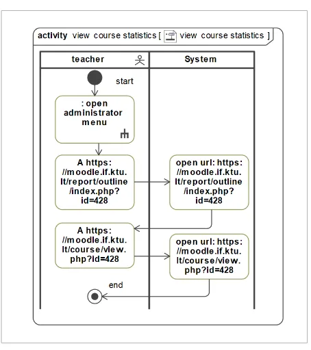
Activity diagram for use case of viewing the statistics of the course is presented in Figure 10.
Include relation was correctly represented in
generated activity diagram – reference to activity for use case of opening administration menu was inserted in the beginning of the generated diagram. Reference to included use cases’ activity diagram is indicated by the colon before action's name and can be additionally represented using the rake icon inside the action node.
Figure 10
Activity diagram for the recorded process of viewing course statistics in Moodle website
Both include and extend relations were properly de-tected in reversed use case model. Use cases of view-ing course statistics and changview-ing users’ registration information included the set of actions for opening ad-ministrator menu. Therefore, this action set was
trans-ferred into included use case and connected to includ-ing use cases by include relations. For the use case of managing resources, three alternative scenarios were recorded and combined into a single use case. For this process, two additional extending use cases were cre-ated (remove resource and create new resource). Activity diagrams were generated for every use case in reversed model for Moodle website. An example of activity diagram for login process is presented in Figure 9. Each activity diagram has two swimlanes, representing the user and the system under analy-sis. Actions are named using the information ex-tracted from websites HTML code where possible. Some system actions (e.g. process form data) were named according to the expected typical reactions of the system.
student and teacher. The tasks, that might be familiar to the experts, were chosen for clarity of the generated models. Student logged in and performed some tasks – downloaded course material, completed a test composed of 10 questions, and filled out a feedback form. Teacher logged in as well, then downloaded course material, and completed the same test. Additionally, teacher added a new file and removed an old one from the course, as well as edited a students’ registration date.
The reversed use case diagram for Moodle website is presented in Figure 8. The tool detected generalization between student and teacher actors: their sets of use cases had intersection including processes of logging in, downloading file and performing test. Therefore, additional actor was created (course user) and associated with use cases from the intersection set. Both include and extend relations were properly detected in reversed use case model. Use cases of viewing course statistics and changing users’ registration information included the set of actions for opening administrator menu. Therefore, this action set was transferred into included use case and connected to including use cases by include relations. For the use case of managing resources, three alternative scenarios were recorded and combined into a single use case. For this process, two additional extending use cases were created (remove resource and create new resource).
Figure 8
Use case diagram reversed engineered from Moodle website
Activity diagrams were generated for every use case in reversed model for Moodle website. An example of activity diagram for login process is presented in Figure 9. Each activity diagram has two swimlanes, representing the user and the system under analysis.
Actions are named using the information extracted from websites HTML code where possible. Some system actions (e.g. process form data) were named according to the expected typical reactions of the system.
Figure 9
Activity diagram for the recorded process of logging in to Moodle website
Activity diagram for use case of viewing the statistics of the course is presented in Figure 10.
Include relation was correctly represented in
generated activity diagram – reference to activity for use case of opening administration menu was inserted in the beginning of the generated diagram. Reference to included use cases’ activity diagram is indicated by the colon before action's name and can be additionally represented using the rake icon inside the action node.
Figure 10
Activity diagram for the recorded process of viewing course statistics in Moodle website
633 Information Technology and Control 2018/4/47
administration menu was inserted in the beginning of the generated diagram. Reference to included use cas-es’ activity diagram is indicated by the colon before action’s name and can be additionally represented us-ing the rake icon inside the action node.
Figure 10
Activity diagram for the recorded process of viewing course statistics in Moodle website
For reversing the second use case model, a usage of ResearchGate website (https://researchgate.net) was recorded. Two user roles were defined: one for the author and the other for the reader. Reader logged in, requested access to the full text of the research publication and viewed job listings. The author performed the same processes as the reader. Additionally, the author changed his profile settings, edited one research publication and removed one research publication. The author also added a new research publication (two scenarios were recorded for this process: one for just adding the publication information, and the other for adding publication information with additional actions of attaching a file). Reverse engineered use case diagram for ResearchGate website is presented in Figure 11. In generated diagram, generalization between actors was successfully detected and created, as the author inherits all use cases associated with the reader. Included use case of viewing the contributions was created. This included use case was connected using
include relation to use cases of research item editing
and removing. Extending use case was also created for the use case of adding the new research publication. Figure 11
Use case diagram reversed engineered from ResearchGate website
The activity diagram for the use case of adding new research publication is presented in Figure 12. As two scenarios were recorded for this use case, the tool combined them into one activity diagram. During the process of combining,
extend relation was detected and new extending
use case for adding a file was created. This was also represented in extended use cases’ activity diagram in Figure 12, as it contains both decision and merge nodes and a reference
(callBehaviorAction) to the extending use cases’
activity diagram. Figure 12
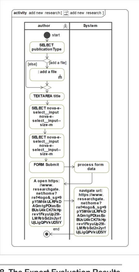
Activity diagram for the recorded process of adding new research publication in ResearchGate website
Figure 11
Use case diagram reversed engineered from ResearchGate website
For reversing the second use case model, a usage of ResearchGate website (https://researchgate.net) was recorded. Two user roles were defined: one for the author and the other for the reader. Reader logged in, requested access to the full text of the research publication and viewed job listings. The author performed the same processes as the reader. Additionally, the author changed his profile settings, edited one research publication and removed one research publication. The author also added a new research publication (two scenarios were recorded for this process: one for just adding the publication information, and the other for adding publication information with additional actions of attaching a file). Reverse engineered use case diagram for ResearchGate website is presented in Figure 11. In generated diagram, generalization between actors was successfully detected and created, as the author inherits all use cases associated with the reader. Included use case of viewing the contributions was created. This included use case was connected using
include relation to use cases of research item editing
and removing. Extending use case was also created for the use case of adding the new research publication. Figure 11
Use case diagram reversed engineered from ResearchGate website
The activity diagram for the use case of adding new research publication is presented in Figure 12. As two scenarios were recorded for this use case, the tool combined them into one activity diagram. During the process of combining,
extend relation was detected and new extending
use case for adding a file was created. This was also represented in extended use cases’ activity diagram in Figure 12, as it contains both decision and merge nodes and a reference
(callBehaviorAction) to the extending use cases’
activity diagram. Figure 12
Activity diagram for the recorded process of adding new research publication in ResearchGate website
For reversing the second use case model, a usage of ResearchGate website (https://researchgate.net) was recorded. Two user roles were defined: one for the author and the other for the reader. Reader logged in, requested access to the full text of the research publi-cation and viewed job listings. The author performed the same processes as the reader. Additionally, the au-thor changed his profile settings, edited one research publication and removed one research publication. The author also added a new research publication (two scenarios were recorded for this process: one for just adding the publication information, and the oth-er for adding publication information with additional actions of attaching a file).
Reverse engineered use case diagram for Research-Gate website is presented in Figure 11. In generated diagram, generalization between actors was
success-fully detected and created, as the author inherits all use cases associated with the reader. Included use case of viewing the contributions was created. This included use case was connected using include rela-tion to use cases of research item editing and remov-ing. Extending use case was also created for the use case of adding the new research publication.
The activity diagram for the use case of adding new research publication is presented in Figure 12. As two scenarios were recorded for this use case, the tool combined them into one activity diagram. During the process of combining, extend relation was detected and new extending use case for add-ing a file was created. This was also represented in extended use cases’ activity diagram in Figure 12, as it contains both decision and merge nodes and a reference (callBehaviorAction) to the extending use cases’ activity diagram.
Information Technology and Control 2018/4/47 634
Figure 12
Activity diagram for the recorded process of adding new research publication in ResearchGate website
The generated models along with the predefined scenarios were provided to experts for evaluation. A questionnaire was prepared for evaluating the models. The experts answered equivalent questionnaire questions for both Moodle and ResearchGate use case models.
8. The Expert Evaluation Results
Altogether, 13 experts completed the anonymous questionnaire. Before evaluating the models, experts were asked to outline their experience in UML modelling. In total, four of the experts declared, that they are OMG certified UML Professionals: two Intermediate and two Advanced level. The declared expert experience in UML modelling varies: six of them have nine or more years of experience, two have between five and eight years of experience and five experts have between two and four years of experience.
The questions in the questionnaire were grouped according to the evaluated diagram type. Two question groups were created – one for use case diagram and the other for all activity diagrams in the
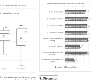
model. For evaluation, experts had to choose a score from one to ten for each question. The questions for both groups are presented in Table 1. Questions in questionnaire were designed to evaluate syntax and semantics of generated UML use case model. Experts were asked to evaluate use case diagrams by assessing overall quality of generated use case diagram (question 1) and elements of the diagram as well as their relations (question 2-4). Experts also had to evaluate the naming of use case diagram elements (question 5). Activity diagrams were evaluated by assessing the overall quality of the scenarios’ representations (question 6). Experts were asked to assess the consistency between use case and activity diagrams: how extend and include relations correspond to specific combinations of elements in activity diagrams (question 7). In addition, the quality of generated names for activity diagram elements was assessed (question 8). All questions in the questionnaire were of equal weight.
Table 1
The list of questions in model evaluation questionnaire
Use case diagram evaluation
1. Rate the quality of the generated use case diagram for given system scenarios 2. Rate the quality of the generated
generalization relations between actors 3. Rate the quality of the generated extend
relations between use cases
4. Rate the quality of the generated include relations between use cases
5. Rate the quality of use case diagram element names
Activity diagrams evaluation
6. Rate the quality of the generated activity diagrams for given system scenarios 7. Rate the quality of include and extend relations’ representation in activity diagrams
8. Rate the quality of activity diagrams element names
Out of the collected responses, the arithmetic means of each expert evaluation scores for Moodle and ResearchGate use case models were calculated (Figure 13). As we can see, the use case model for Moodle website was evaluated more favorably with mean score of 8.5 and a much smaller distribution between expert given scores. ResearchGate evaluation score is more varied: the mean score of 8.3 is fairly similar, but with larger distribution of given scores. Larger
8. The Expert Evaluation Results
Altogether, 13 experts completed the anonymous questionnaire. Before evaluating the models, experts were asked to outline their experience in UML mod-elling. In total, four of the experts declared, that they are OMG certified UML Professionals: two Interme-diate and two Advanced level. The declared expert ex-perience in UML modelling varies: six of them have nine or more years of experience, two have between
five and eight years of experience and five experts have between two and four years of experience. The questions in the questionnaire were grouped ac-cording to the evaluated diagram type. Two question groups were created – one for use case diagram and the other for all activity diagrams in the model. For evalu-ation, experts had to choose a score from one to ten for each question. The questions for both groups are pre-sented in Table 1. Questions in questionnaire were de-signed to evaluate syntax and semantics of generated UML use case model. Experts were asked to evaluate use case diagrams by assessing overall quality of generated use case diagram (question 1) and elements of the dia-gram as well as their relations (question 2-4). Experts also had to evaluate the naming of use case diagram el-ements (question 5). Activity diagrams were evaluated by assessing the overall quality of the scenarios’ repre-sentations (question 6). Experts were asked to assess the consistency between use case and activity diagrams: how extend and include relations correspond to specific combinations of elements in activity diagrams (question 7). In addition, the quality of generated names for activi-ty diagram elements was assessed (question 8). All ques-tions in the questionnaire were of equal weight.
Table 1
The list of questions in model evaluation questionnaire
Use case diagram evaluation
1. Rate the quality of the generated use case diagram for given system scenarios
2. Rate the quality of the generated generalization relations between actors
3. Rate the quality of the generated extend relations between use cases
4. Rate the quality of the generated include relations between use cases
5. Rate the quality of use case diagram element names
Activity diagrams evaluation
6. Rate the quality of the generated activity diagrams for given system scenarios
7. Rate the quality of include and extend relations’ representation in activity diagrams
![Figure 6 matchingUseCases[j].insertCallBehaviorAction(matchingSequences[i]);}}} The implemented WEB2UML plugin](https://thumb-us.123doks.com/thumbv2/123dok_us/8763908.1753432/8.595.309.523.331.679/figure-matchingusecases-insertcallbehavioraction-matchingsequences-implemented-web-uml-plugin.webp)