Abstract
In most flow applications require regulating the flow of liquid, and usually the parameter of concern is the pressure. This paper focuses on analysis of flow regulating pressure valve by Finite |Element Analysis by using nonlinear and transient finite element analysis. To control the pressure of fluid electronically or pneumatically operated valves are used. Sometime there is requirement to mechanically operated valve. Only one valve which will connect three different chambers and will control the flow between chambers by using balance stiffness based valve. The static analysis is used to determine the deformation and stresses in the valve whereas the transient analysis is used to determine the dynamic response of valve under any time dependent loads. The Transient solution was extremely useful in order to know the effects of friction and bending pressure parameters. The main purpose to design this valve is to maintain pressure inside the pressure vessel at specific level to avoid the busting of the pressure vessel. The idea behind this project is to introduce regulation by manipulating the direction of flow.
Keywords: Valve Design, Finite Element Analysis
_______________________________________________________________________________________________________
I. INTRODUCTION
In Pneumatic, hydraulic and electronic systems control of fluid is mainly based on parameter pressure. Every System requires some source of power like compressed air or electricity. There is not much work done in the field of flow control pressure valve which is operating all the time, especially when the power failure and when the controls are not working. Finite Element Analysis is the simulation technique which is used to find the behavior of components, structure and equipment’s for different load conditions such as pressure, temperatures and forces. Many complicated problems with non- standard geometry and shape can be solved with the help of finite element analysis. Valve is the important component in flow control. Valve is continuously operated for mixing of two different fluids so it is essential to understand the transient and structural behavior of the valve. Technical data
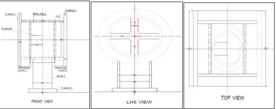
Input Dimensions
1) Main Shell Diameter -100mm 2) Nozzle Diameter – 60mm
3) Valve operating pressure from side1-0.2 Mpa 4) Valve operating pressure from side2-0.185 Mpa
5) Springs required – 5 Nos
Dimensions and Material of Different Parts of valves
1) Main Shell: - Material - SA516Gr70, Thickness-6mm, Length-135mm, Diameter -100mm 2) Nozzle- Material – SA-106GRB, Thickness-6mm, Length-90mm, Diameter -60mm 3) Circular Pressure Plate- Material -SA516Gr70, Thickness-3mm, Diameter -100mm 4) Flange- Material -SA516Gr70
a) Main shell- Thickness-10mm, Outer Diameter-150mm, Inner Diameter -100mm b) Nozzle- Thickness-10mm, Outer Diameter-90mm, Inner Diameter -60mm 5) Reinforcement Pad- Outer Diameter-80.5mm
6) Clit- Material -SA516Gr70, Thickness-3mm, Outer Diameter-100mm, Inner Diameter -95mm
Fig. 1: Drawing for Flow Regulating Pressure Valve
II. STATIC STRUCTURAL ANALYSIS
Static structural analysis is used to determine deformation, stresses etc. under static loading condition for both linear and nonlinear analysis. Non linearity can include plasticity, hyper elasticity, large deflection, stress stiffening, contact surface and creep. Two cases are considered in static structural settings which are as follows.
Cases for FEA Analysis-
1) Case 1 - Condition- Flange 1, Flange 2, Flange 3 are fixed and pressure 0.185 MPa applied on pressure plate 1. 2) Case 2 - Flange 1, Flange 2, Flange 3 are fixed and pressure 0.2 MPa applied on pressure plate 2.
Model
Initially CAD model for flow regulating pressure valve is done. This modeling is done with ANSYS workbench 15. Fillets and chamfers are not considered to avoid the difficulties in meshing.
Meshing Details
Element Type : SOLID 186
Method of mesh control : Hex Dominant
Size : 3 mm
Statistics
No. of nodes : 158087
No. of elements : 38067
Fig. 2: CAD and Meshing of Model -Flow Regulating Valve
Model Analysis
Fig. 3: Boundary condition, Deformation and Equivalent Stresses for case 1
Boundary Conditions and Solution for Case 2:
Fig. 4: Boundary condition, Deformation and Equivalent Stresses for case 2
Result of Finite Element Analysis
Table 1 shows the result of finite element analysis in which maximum and minimum total deformation and equivalent stresses for case 1 and case2 mentioned.
Table – 1
Result of Finite Element Analysis
Sr. No. Parameter Case 1 Case 2
Min Max Min Max
1 Equivalent Stress (Mpa) 0.0004699 38.626 0.00042137 38.958
2 Total Deformation (mm) 0 36.493 0 36.782
III. TRANSIENT FINITE ELEMENT ANALYSIS
After static structural analysis it is required to do the transient analysis for complete valve body. In static structural analysis load is applied on body in 1 step where as in transient analysis it is applied in 3 steps. Each step is of 1sec. Plate area blowing up to fluid flow at inlet side is divided into 3 load steps. As pressure on circular pressure plate increases plate will move forward against the spring force and therefore at particular time‘t’ each step is undergoing different pressure.
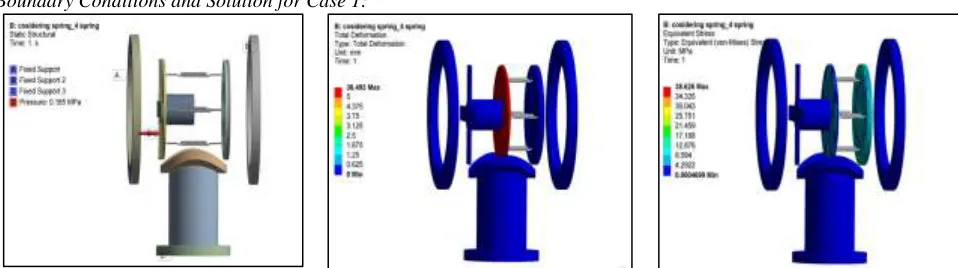
Boundary Conditions and Solution for Case 1:
Fig. 5: Boundary condition for case 1
Fig. 6: Deformation and Equivalent Stresses for case 1
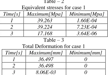
Result of Transient Analysis for Case 1
Table – 2
Equivalent stresses for case 1
Time[s] Maximum[Mpa] Minimum[Mpa]
1 39.263 1.60E-04
2 39.224 7.23E-04
3 17.168 3.64E-06
Table – 3
Total Deformation for case 1
Time[s] Maximum[mm] Minimum[mm]
1 36.497 0
2 36.498 0
3 8.06E-03 0
Boundary Conditions and Solution for Case 2:
Fig. 7: Boundary condition for case 2
Fig. 8: Deformation and Equivalent Stresses for case 2
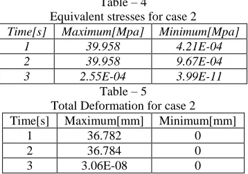
Result of Transient Analysis for Case 2
Table – 4
Equivalent stresses for case 2
Time[s] Maximum[Mpa] Minimum[Mpa]
1 39.958 4.21E-04
2 39.958 9.67E-04
3 2.55E-04 3.99E-11
Table – 5
Total Deformation for case 2 Time[s] Maximum[mm] Minimum[mm]
1 36.782 0
2 36.784 0
IV. CONCLUSIONS
1) The outputs obtained from structural analysis are equivalent stress and total deformation. From structural point of view, it is necessary that the stress induced in valve must be less than design stress.
2) From analysis it is been observed that for case 1 and case 2 maximum equivalent stresses are 38.626 Mpa and 38.958 Mpa respectively which are less than design stress. So the design is safe.
3) Total deformations observed for case 1 and case 2 are 36.493 and 36.782 mm. respectively which is sufficient for the performance of the balanced stiffness Valve.
4) Transient analysis shows maximum stresses developed in case1 & case 2 are within the permissible safety limit also deformation is also sufficient enough for valve performance.
ACKNOWLEDGMENT
Thanks to Prof. Siddaram Biradar for his valuable contribution for motivation and support for developing this work.
REFERENCES
[1] Xue-Guan Song, Young-Chul Park, Joon-Hong Park “Blowdown prediction of a conventional pressure relief valve with a simplified dynamic model” Mathematical and Computer Modelling 57 (2013) 279–288
[2] A.Beune ,J.G.M.Kuerten, M.P.C. van Heumen,2012 “CFD analysis with fluid–structure interaction of opening high–pressure safety valves.” Computers & Fluids 64 (2012) 108-116
[3] N.N. Manchekar, V. Murali Mohan,2013, “Design of gradual flow reducing valve by finite element analysis” International Journal of Engineering & Science Research June 2013 Volume 3, Issue-6,Pages 257-267.
[4] Binod Kumar Saha, Himadri Chattopadhyay, Pradipta Basu Mandal, Tapas Gangopadhyay, “Dynamic simulation of a pressure regulating and shut-off valve.” Journal of Computers & Fluids 101 (2014) 233–240.
[5] A.J.Ortega, B. N. Azevedo, L. F. G. Pires, A. O. Nieckele, L. F. A. Azevedo, “Analysis of the discharge coefficient of a spring loaded pressure relief valve during its dynamic behavior”. Journal of International Congress of Mechanical Engineering November 15-20, 2009.
[6] Mr.V.D.Rathod, Prof.G.A.Kadam, “Design and Analysis of Pressure Safety Release Valve by using Finite Element Analysis”. International Journal of Engineering Trends and Technology (IJETT) – Volume 13 Number 1 – Jul 2014
[7] Sushant M. Patil , Ramchandra G. Desavale , Imran M. Jamadar , “Conceptual Structure Design Through Thickness Optimization Of High Pressure And High Temperature Self-Regulated Pressure Valve Using Non-Linear Transient Finite Element Method”. International Journal of Engineering Research & Technology June 2013 Volume 2 Issue 6.
[8] Ron Darby, “The dynamic response of pressure relief valves in vapor or gas service, part I: Mathematical model”. Journal of Loss Prevention in the Process Industries, 2013,1-7.
[9] M. R. Mokhtanadeh-Dehghan, N. Ladommatos, and T. J. Brennan, “Finite element analysis of flow in a hydraulic pressure valve”. Applied Mathematical Modelling Volume 21, Issue 7, July 1997, Pages 437–445
[10] CASTI Guidebook Series - Volume 4 to ASME Section VIII Division 1 for Pressure Vessels‖ Bruce E. Ball, Will J. Carter, Third Edition (Covering 2001 Edition ofASME Section VIII Division 1).