Design and Analysis of Automotive Composite
Propeller Shaft
Ravi Vattipalli P. S. Naga Sri
Department of Mechanical Engineering Department of Mechanical Engineering
D.M.S.S.V.H College of Engineering, and Machilipatnam, India
D.M.S.S.V.H College of Engineering, and Machilipatnam, India
Abstract
Substituting composite structures for conventional metallic structures has many advantages because of higher specific stiffness and strength of composite materials. This work deals with the replacement of conventional steel propeller shafts with Kevlar and high modulus carbon/epoxy composite propeller shafts for an automotive application. The design parameters were optimized with the objective of minimizing the weight of composite propeller shaft. The design optimization also showed significant potential improvement in the performance of propeller shaft.
Keywords: Torque transmission, Torsional buckling capacities, Fundamental lateral Natural frequency, Bernoulli Euler theory, Timoshenko beam theory, Static analysis, Modal analysis, Buckling analysis, ANSYS
_______________________________________________________________________________________________________ I. INTRODUCTION
The advanced composite materials such as graphite, Kevlar, glass and carbon with suitable resins are widely used because of their high specific strength and high specific modulus for long, power drive shaft applications (for example: propeller shaft) advanced composite materials are ideally suited. And their elastic properties can be tailored to increase the torque they can carry as well as the rotational speed at which they operate. The propeller shafts are used in automotive, air craft and marine drive applications. The automotive industry is exploiting composite material technology for structural component construction in order to obtain the reduction of weight without decrease in vehicle quality and reliability. It is known that energy conservation is one of the most important objective in vehicle design and reduction of weight is one of the most effective measure to obtain this result. In fact, there is almost a direct proportionality between the weight of a vehicle and its fuel consumption, particularly in heavy traffic areas like city driving.
II. LITERATURESURVEY
Composites
The theoretical details of composite materials and composite structures are extensively reviewed [6]. The Spicer U-Joint Division of Dana Corporation for the Ford Econoline van models developed the first composite propeller shaft in 1985. The General Motors pickup trucks, which adopted the Spicer product, enjoyed a demand three times that of projected sales in its first year [4, 5]. John. W. Weeton et al. [7] briefly described the application possibilities of composites in the field of automotive industry to manufacture composite elliptic springs, drive shafts and leaf springs. Beard more and Johnson [8] discussed the potential for composites in structural automotive applications from a structural point of view. Pollard [9] studied the possibility of the polymer Matrix composites usage in driveline applications. Faust et.al, [10] described the considerable interest on the part of both the helicopter and automobile industries in the development of lightweight propeller shafts.
Procedure for finding the elastic moduli of anisotropic laminated composites is explained by Azzi.V.D et.al, [11]. Azzi.V.D .et.al, discussed about anisotropic strength of composites[12]
Torsional Buckling
The problem of general instability under torsional load has been studied by many investigators. Greenhill [13] obtained a solution for the torsional stability of a long shaft. The first analysis of buckling of thin-walled tubes under torsion made by Schwerin [14], but his analysis did not agree with his experimental data. However, all these papers were limited to isotropic materials.
shafts, which were in good agreement with theoretical predictions based on a general shell theory including elastic coupling effects and transverse shearing deformations.
Lateral Vibrations
Bauchau [21] developed procedure for optimum design of high-speed composite propeller shaft made of laminates to increase the first natural frequency of the shaft and to decrease the bending stress. Shell theory based on the critical speed analyses of propeller shafts has been presented by Dos Reis et al. [22]. Patricia L.Hetherington [23] investigated the dynamic behavior of supercritical composite propeller shafts forhelicopter applications. Ganapathi.et.al [24] extensively studied the nonlinear free flexural vibrations of laminated circular cylindrical shells. A method of analysis involving Love’s first approximation theory and Ritz’s procedure is used to study the influence of boundary conditions and fiber orientation on the natural frequencies of thin orthotropic laminated cylindrical shells was presented [25].A first order theory was presented by Lee[26] to determine the natural frequencies of a n orthotropic shell. Nowinski.J.L.[27] investigated the nonlinear transverse vibrations of elastic orthotropic shells using Von-Karman-Tsien equations
Optimization
The optimum design of laminated plates and shells subjected to constraints on strength, stiffness, buckling loads, and fundamental natural frequencies were examined [28]. Methods were proposed for the determination of the optimal ply angle variation through the thickness of symmetric angle-ply shells of uniform thickness [29]. The main features of GAs and several ways in which they can solve difficult design problems were discussed by Gabor Renner et.al.[30]. Raphael T.Haftka [31] discussed extensively about stacking-sequence optimization for buckling of laminated plates by integer programming. The use of a GA to optimize the stacking sequenceof composite laminates for buckling load maximization was studied. Various genetic parameters including the population size, the probability of mutation, and the probability of crossover were optimized by numerical experiments [32]. The use of GAs for the optimal design of symmetric composite laminates subject to various loading and boundary conditions were explained [33]. Kim, et.al. [34] minimized the weight of composite laminates with ply drop under a strength constraint. The working of Simple Genetic Algorithm was explained by Goldberg [35]. Rajeev and Krishnamurthy [36] proposed a method for converting a constrained optimization problem into an unconstrained optimization problem
III. COMPOSITE MATERIALS FOR PROPELLER SHAFT
Composites consist of two or more materials or material phases that are combined to produce a material that has superior properties to those of its individual constituents. The constituents are combined at a macroscopic level and or not soluble in each other. the main difference between composite and an alloy are constituent materials which are insoluble in each other and the individual constituents retain those properties in the case of composites, where as in alloys, constituent materials are soluble in each other and forms a new material which has different properties from their constituents.
Classification of Composites
Composite materials can be classified as
Polymer matrix composites
Metal matrix composites
Ceramic Matrix
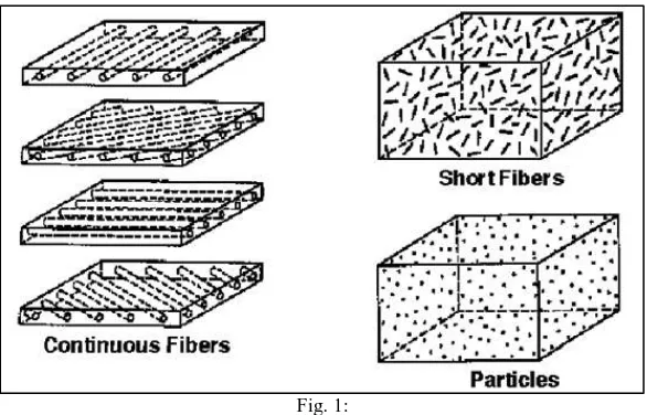
Technologically, the most important composites are those in which the dispersed phase is in the form of a fiber. The design of fiber-reinforced composites are based on the high strength and stiffness on a weight basis. Specific strength is the ratio between strength and density. Specific modulus is the ratio between the modulus and density. Fiber length has a great influence on the mechanical characteristics of a material. The fibers can be either long or short. long continuous fibers are easy to orient and process, while short fibers cannot be controlled fully for proper orientation. long fibers provide many benefits over short fibers. these includes impact resistance, low shrinkage, improved surface finish and dimensional stability. however short fibers provide low cost, are easy to work with, and have fast cycle time fabrication procedures. the characteristics of the fiber- reinforced composites depend not only on the properties of the fiber, but also on the degree to which an applied load is transmitted to the fibers by the matrix phase.
Fig. 1:
Advantages of Fiber Reinforced Composites
The advantages of composites over the conventional materials are
High strength to weight ratio
High stiffness to weight ratio
High impact resistance
Better fatigue resistance
Improved corrosion resistance
Good thermal conductivity
Low Coefficient of thermal expansion.
As a result, composite structures may exhibit a better dimensional stability over a wide temperature range. High damping capacity Limitations of Composites
The limitations of composites are
Mechanical characterization of a composite structure is more complex than that of a metallic structure
The design of fiber reinforced structure is difficult compared to a metallic
structure, mainly due to the difference in properties in directions
The fabrication cost of composites is high
Rework and repairing are difficult
They do not have a high combination of strength and fracture toughness as compared to metals
They do not necessarily give higher performance in all properties used for material selection Applications of Composites
The common applications of composites are extending day by day. Nowadays they are used in medical applications too. The other fields of applications are,
Automotive: propeller shafts, clutch plates, engine blocks, push rods, frames, Valve guides, automotive racing brakes, filament– wound fuel tanks, fiber Glass/Epoxy leaf springs for heavy trucks and trailers, rocker arm covers, suspension arms and bearings for steering system, bumpers, body panels and doors
Aircraft: Drive shafts, rudders, elevators, bearings, landing gear doors, panels and floorings of airplanes etc.
Space: payload bay doors, remote manipulator arm, high gain antenna, antenna ribs and struts etc.
Marine: Propeller vanes, fans & blowers, gear cases, valves &strainers, condenser shells.
Chemical Industries: Composite vessels for liquid natural gas for alternative fuel vehicle, racked bottles for fire service, mountain climbing underground storage tanks, ducts and stacks etc.
Electrical & Electronics: Structures for overhead transmission lines for railways, Power line insulators, Lighting poles, Fiber optics tensile members etc.
Sports Goods: Tennis rackets, Golf club shafts, Fishing rods, Bicycle framework, Hockey sticks, Surfboards, Helmets and others
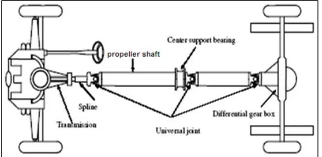
Purpose of the Propeller Shaft
Fig. 2: Propeller Shaft of a Tata Safari Dicor
Functions of the Propeller Shaft
1) First, it must transmit torque from the transmission to the differential gearbox.
2) During the operation, it is necessary to transmit maximum low-gear torque developed by the engine. 3) The propeller shafts must also be capable of rotating at the very fast speeds required by the vehicle.
4) The propeller shaft must also operate through constantly changing angles between the transmission, the differential and the axles. As the rear wheels roll over bumps in the road, the differential and axles move up and down. This movement changes the angle between the transmission and the differential.
5) The length of the propeller shaft must also be capable of changing while transmitting torque. Length changes are caused by axle movement due to torque reaction, road deflections, braking loads and so on. A slip joint is used to compensate for this motion. The slip joint is usually made of an internal and external spline. It is located on the front end of the propeller shaft and is connected to the transmission.
Different Types of Shafts
Transmission Shaft:
These shafts transmit power between the source and the machines absorbing power. The counter shafts, line shafts, overhead shafts and all factory shafts are transmission shafts. Since these shafts carry machine parts such as pulleys, gears etc. therefore they are subjected to bending moments in addition to twisting
Machine Shaft:
These shafts form an integral part of the machine itself. For example, the crankshaft is an integral part of I.C. engines slider-crank mechanism.
Axle:
A shaft is called “an axle”, if it is a stationary machine element and is used for the transmission of bending moment only. It simply acts as a support for rotating bodies.
Application:
To support hoisting drum, a car wheel or a rope sheave. Spindle:
A shaft is called “a spindle”, if it is a short shaft that imparts motion either to a cutting tool or to a work-piece. Applications:
Drill press spindles-impart motion to cutting tool (i.e.) drill,Lathe spindles-impart motion to work-piece Apart from, an axle and a spindle, shafts are used at so many places and almost everywhere wherever power transmission is required. Few of them are:
Automobile Drive Shaft:
Transmits power from main gearbox to differential gearbox. Ship Propeller Shaft:
Transmits power from gearbox to propeller attached on it. Helicopter Tail Rotor Shaft:
Transmits power to rail rotor fan. This list has no end, since in every machine, gearboxes, automobiles etc. shafts are there to transmit power from one end to other
Propeller Shaft Arrangement in a Car Model
Fig. 3: Conventional two-piece propeller shaft arrangements for rear wheel vehicle driving system
Part of propeller Shaft and Universal Joint
Parts of propeller shaft and universal joint are shown in fig.. Parts of propeller shaft and universal joints are
Fig. 4: Parts of Propeller shaft and universal joint
1) U-bolt nut 2) U-bolt washers 3) U-bolt
4) Universal joint journal 5) Lubrication fitting 6) Snap ring.
7) Universal joint sleeve 8) Spline seal
9) Dust cap
10) propeller shaft tube
IV. DESIGN OF STEEL PROPELLER SHAFT
Specification of the Problem
The fundamental natural bending frequency for passenger cars, small trucks, and vans of the propeller shaft should be higher than 6,500 rpm to avoid whirling vibration and the torque transmission capability of the propeller shaft should be larger than 3,500 Nm. The propeller shaft outer diameter should not exceed 100 mm due to space limitations. Here outer diameter of the shaft is taken as 63.7 mm. The propeller shaft of transmission system is to be designed optimally for following specified design requirements a s shown in Table.1.
Table – 1
Design requirements and specifications
Sl.No. Name Notation Unit Value
1. Ultimate Torque Tmax Nm 3200
2. Max. Speed of shaft Nmax rpm 10950
Steel (SM45C) used for automotive propeller shaft applications. The material properties of the steel (SM45C) are given in Table 2. The steel propeller shaft should satisfy three design specifications such as torque transmission capability, buckling torque capability and bending natural frequency.
Table – 2
Mechanical properties of Steel (SM45C)
Mechanical properties Value
Young’s modulus, Gpa 207.0
Shear modulus, Gpa 80
Poison’s ratio 0.3
Density, Kg/m3 7850
Yield strength, Mpa 370
Torque Transmission capacity of the propeller Shaft
T = SS
π(do 4−di4)
16tdo --- (4.1) Torsional Buckling Capacity of the propeller Shaft
It is called as Long shaft otherwise it is called as Short & Medium shaft For long shaft, the critical stress is given by,
τcr =
E
3√2(1−υ2)3⁄4(t r)⁄ 3 2⁄
--- (4.2) For short & medium shaft, the critical stress is given by,
---- (4.3) Lateral or Bending Vibration
The shaft is considered as simply supported beam undergoing transverse vibration or can be idealized as a pinned-pinned beam. Natural frequency can be found using the following two theories
Bernoulli-Euler Beam Theory-Ncrbe,
fnbe =
πp2 2L2√
EIx
m1--- (4.5) Where p = 1,2...……
Ncrbe = 60fnbe --- (4.6) Timoshenko Beam Theory-Ncrt
It considers both transverse shear deformation as well as rotary inertia effects. Natural frequency based on the Timoshenko beam theory is given by
fnt = Ks
30 π p2
L2 √
Er2
2ρ --- (4.7) Ncrt = 60fnt --- (4.8) 1
Ks2 = 1+ n2π2r2
2L2 [1 +
fS E
G ] --- (4.9) fs= 2 for hollow circular cross-sections
The relation between Timoshenko and Bernoulli-Euler Beam Theories.
The relation between Timoshenko and Bernoulli-Euler beam theories is given by, fnt = Ksfnbe --- (4.10)
V. DESIGN OF A COMPOSITE PROPELLERSHAFT
Specification of the Problem
The specifications of the composite propeller shaft of an automotive transmission are same as that of the steel propeller shaft for optimal design.
Assumptions
2) The shaft has a uniform, circular cross-section.
3) The shaft is perfectly balanced, i.e., at every cross section, the mass center coincides with the geometric center. 4) All damping and nonlinear effects are excluded.
5) The stress-strain relationship for composite material is linear & elastic; hence, Hooke’s law is applicable for composite materials.
6) Acoustical fluid interactions are neglected, i.e., the shaft is assumed to be acting in vacuum. 7) Since lamina is thin and no out-of-plane loads are applied, it is considered as under the plane stress.
Selection of Cross-Section
The propeller shaft can be solid circular or hollow circular. Here hollow circular cross-section was chosen because:
The hollow circular shafts are stronger in per kg weight than solid circular.
The stress distribution in case of solid shaft is zero at the center and maximum at the outer surface while in hollow shaft stress variation is smaller. In solid shafts the material close to the center are not fully utilized.
Selection of Reinforcement Fiber
Fibers are available with widely differing properties. Review of the design and performance requirements usually dictate the fiber/fibers to be used
Kevlar fibers:
Its advantages are low density, high tensile strength, low cost, and higher impact resistance. The disadvantages are very low compressive strength, marginal shear strength, and high water absorption. Kevlar is not recommended for use in torque carrying application because of its low strength in compression and shear. Here, both glass and carbon fibers are selected as potential materials for the design of shaft
HM carbon/epoxy:
Its advantages include high specific strength and modulus, low coefficient of thermal expansion, and high fatigue strength. Graphite, when used alone has low impact resistance. Its drawbacks include high cost, low impact resistance, and high electrical conductivity
Selection of Resin System
The important considerations in selecting resin are cost, temperature capability, elongation to failure and resistance to impact (a function of modulus of elongation). The resins selected for most of the propeller shafts are either epoxies or vinyl esters. Here, epoxy resin was selected due to its high strength, good wetting of fibers, lower curing shrinkage, and better dimensional stability
Selection of Materials
Based on the advantages discussed earlier, the High Modulus Carbon/Epoxy materials used for composite propeller shafts
Table - 3
Properties of Kevlar and HM Carbon/Epoxy
SL.NO PROPERTY KEVLAR HM CARBON/
EPOXY
1 Longitudinal elastic modulus of lamina (E11),Gpa 136.0 190.0
2 Transverse elastic modulus of lamina (E22), Gpa 4.2 7.7
3 Shear modulus of lamina (G12), Gpa 2.9 4.2
4 Major Poisson’s ratio(ν12) 0.35 0.35
5 Ultimate longitudinal tensile strength (S
t
1= S c
1), Mpa 800 870
6 Ultimate transverse tensile strength (S
t
2= S c
2), Mpa 53 54
7 Ultimate in-plane shear strength(S12), Mpa 70 30
8 Density (ρ), Kg/m3 1470 1600
Factor of Safety
The designer must take into account the factor of safety when designing a structure. Since, composites are highly orthotropic and their fractures were not fully studied the factor of safety was taken as 2
Torque Transmission Capacity of the Shaft
Stress-Strain Relationship for Unidirectional Lamina
The lamina is thin and if no out-of-plane loads are applied, it is considered as the plane stress problem. Hence, it is possible to reduce the 3-D problem into 2-D problem.
{ σ1 σ2 τ12
} = [
Q11 Q12 0
Q12 Q22 0
0 0 Q66̅̅̅̅̅
] { ε1 ε2 γ12
}--- (5.1)
---- (5.2)
Principal material directions and coordinates X, Y, Z are transformed or laminate axesFor an angle-ply lamina where fibers are oriented at an angle with the positive X-axis (Longitudinal axis of shaft), the effective elastic properties are given by
--- (5.3)
--- (5.4)
s --- (5.5)
The variation of the Exlamina, Eylamina and Gxylamina with ply orientation is shown in Fig 2 and 3 respectively
Fig. 5: The variation of the Exlamina and Eylamina with ply orientation for Hm Carbon/Epoxy
The stress strain relationship for an angle-ply lamina is given by, Q11
̅̅̅̅̅ = Q11C4
Q 22S4 2
Q12 2Q66 S2C 2
𝑄12
̅̅̅̅̅̅ = Q11 Q22 4Q66 S2C2 Q12 (C4 S4 ) 𝑄16
̅̅̅̅̅̅ = (Q11 Q12 2Q66 C3S
(Q22 Q12 2Q66 CS3 ---- (5.6)
Q 22
̅̅̅̅̅̅̅ = Q11S4
Q 22S4 2
Q11 2Q66 S2C2
Q26
̅̅̅̅̅ = Q11 Q12 2Q66 CS3 Q22 Q12 2Q66 C3S Q66
̅̅̅̅̅ = (Q11 Q22 2Q12 2Q66 S2C2 Q66 (S4 C4 ) {
𝜎𝑥 𝜎𝑦 𝜏𝑥𝑦} = [
𝑄11
̅̅̅̅̅ 𝑄̅̅̅̅̅12 𝑄̅̅̅̅̅16 𝑄12
̅̅̅̅̅ 𝑄22̅̅̅̅̅ 𝑄26̅̅̅̅̅ 𝑄16
̅̅̅̅̅ 𝑄̅̅̅̅̅26 𝑄̅̅̅̅̅66 ] {
𝜀𝑥 𝜀𝑦 𝛾𝑥𝑦
}--- (5.7)
Stress-Strain Relationship for Angle-ply Lamina
For symmetric laminates, the B matrix vanishes and the in plane and bending stiffness are uncoupled. For a symmetric laminate, knowing the stresses in each ply, the failure of the laminate is determined by using the First Ply Failure criteria. That is, the laminate is assumed to fail when the first ply fails. Here maximum stress theory is used to find the torque transmitting capacity.
VI. FINITE ELEMENTANALYSIS
Introduction
Finite Element Analysis (FEA) is a computer-based numerical technique for calculating the strength and behavior of engineering structures. It can be used to calculate deflection, stress, vibration, buckling behavior and many other phenomena. It also can be used to analyze either small or large- scale deflection under loading or applied displacement. It uses a numerical technique called the finite element method (FEM)
In this project finite element analysis was carried out using the FEA software ANSYS. The primary unknowns in this structural analysis are displacements and other quantities, such as strains, stresses, and reaction forces, are then derived from the nodal displacements
Mesh Generation:
Mesh generation is the practice of generating a polygonal or polyhedral mesh that approximates a geometric domain. The term "grid generation" is often used interchangeably. Typical uses are for rendering to a computer screen or for physical simulation such as finite element analysis or computational fluid dynamics. The input model form can vary greatly but common sources are CAD, NURBS, B-rep, STL or a point cloud. The field is highly interdisciplinary, with contributions found in mathematics, computer science, and engineering.
Three-dimensional meshes created for finite element analysis need to consist of tetrahedra, pyramids, prisms or hexahedra. Those used for the finite volume method can consist of arbitrary polyhedral. Those used for finite difference methods usually need to consist of piecewise structured arrays of hexahedra known as multi-block structured meshes. A mesh is otherwise a discretization of a domain existing in one, two or three dimensions
Table – 4 Meshing properties
Nodes 11329
Elements 5910
Input Data
The element is defined by eight nodes, average or corner layer thicknesses, layer material direction angles, and orthotropic material properties. A triangular-shaped element may be formed by defining the same node number for nodes K, L and O. The input may be either in matrix form or layer form, depending upon KEYOPT (2). Briefly, the force-strain and moment-curvature relationships defining the matrices for a linear variation of strain through the thickness (KEYOPT (2) = 2) may be defined as:
{N M} = [
A B
B D] {
ε K} − {
MT BT}
Sub matrices [B] and [D] are input similarly. Note that all sub matrices are symmetric. {MT} and {BT} are for thermal effects. The layer number (LN) can range from 1 to 250. In this local right-handed system, the x'-axis is rotated an angle THETA (LN) (in degrees) from the element x-axis toward the element y-axis. The total number of layers must be specified (NL). The properties of all layers should be entered (LSYM = 0). If the properties of the layers are symmetrical about the mid-thickness of the element (LSYM= 1), only half of properties of the layers, up to and including the middle layer (if any), need to be entered. While all layers may be printed, two layers may be specifically selected to be output (LP1 and LP2, with LP1 usually less than LP2).
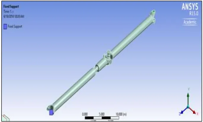
Boundary Conditions
The finite element model of Hm Carbon/Epoxy shaft is one end is fixed and torque is applied at other end
Fig. 7: Finite element model of Hm Carbon/Epoxy shaft
Modal Analysis
When an elastic system free from external forces is disturbed from its equilibrium position it vibrates under the influence of inherent forces and is said to be in the state of free vibration. It will vibrate at its natural frequency and its amplitude will gradually become smaller with time due to energy being dissipated by motion. The main parameters of interest in free vibration are natural frequency and the amplitude. The natural frequencies and the mode shapes are important parameters in the design of a structure for dynamic loading conditions.
Modal analysis is used to determine the vibration characteristics such as natural frequencies and mode shapes of a structure or a machine component while it is being designed. It can also be a starting point for another more detailed analysis such as a transient dynamic analysis, a harmonic response analysis or a spectrum analysis. Modal analysis is used to determine the natural frequencies and mode shapes of a structure or a machine component
The rotational speed is limited by lateral stability considerations. Most designs are sub critical, i.e. rotational speed must be lower than the first natural bending frequency of the shaft. The natural frequency depends on the diameter of the shaft, thickness of the hollow shaft, specific stiffness and the length Boundary conditions for the modal analysis are shown in Fig 8.
Fig. 8: Boundary Conditions for the Modal Analysis
Buckling Analysis
Analysis is a technique used to determine buckling loads (critical loads) at which a structure becomes unstable, and buckled mode shapes (The characteristic shape associated with a structure's buckled response).
capabilities. The dominant failure mode, torsional buckling, is strongly dependent on fiber orientation angles and ply stacking sequence
VII.RESULTS AND DISCUSSIONS
Analytical Analysis
A composite propeller shaft for rear wheel drive automobile was designed optimally. Kevlar and High Modulus Carbon/Epoxy composites with the objective of minimization of weight of the shaft which is subjected to the constraints such as torque transmission, torsional buckling capacities and natural bending frequency.
Summarization Analytical Results
Table – 5 Analytical results
PARAMETERS STEEL KEVLAR HM CARBON/EPOXY
do (mm) 63.7 63.7 63.7
L (mm) 1530 1530 1530
t (mm) 8.04 10.8 8.634
Weight (grams) 16875 4035 3662
Weight saving (%) - 76.08 78.29
Stresses of a Propeller Shaft
Stresses of a propeller shaft of proposed materials Using torque transmission capacity of the shaft by using the analytical methods as shown in the table 6.
Table - 6
Critical shear stress and critical stress of proposed materials
MATERIAL STEEL KEVLAR HM CARBON/EPOXY
Critical Shear stress, pa (τcr) 37440 53891 29610
Shear Strength, pa (Ss) 36788 50957 25713
Torsional Buckling Capacity of the Propeller Shaft with Proposed Materials
Table – 7
Torsional Buckling Capacity of propeller Shafts
MATERIAL STEEL KEVLAR HM CARBON/EPOXY
Tcr (N- m) 1.55 1.39 3.07
Bending natural frequency of a propeller shaft Using Bernoulli-Euler Beam Theory and Timoshenko Beam
MATERIAL STEEL KEVLAR HM CARBON/EPOXY
f
nbe, Hz 179.89 146.27 124.27
f
nt ,Hz 137.71 121.56 146.87
Rotational speed of a propeller shaft by Bernoulli-Euler Beam Theory and Timoshenko beam theory
MATERIAL STEEL KEVLAR HM CARBON/EPOXYY
Ncrbe ,r.p.m 10971 8788.36 7456.26
Ncrt, r.p.m 8262.86 6063.271 7392.82
Numerical analysis: Static structural analysis results
Fig. 9: Equivalent stresses of a steel propeller shaft
Equivalent (Von-mises) stresses ofKevlar and Hm Carbon Propeller shaft using Ansys workbench as shown in the figure respectively
Fig. 10: Equivalent stresses of a of Kevlar Fig. 11: Equivalent stresses of a Hm carbon /epoxy
Graph of von- mises stresses with conventional steel, Kevlar and Hm carbon propeller shaft for a particular load as shown in the figure
Total deformation of a conventional steel propeller shaft using Ansys work bench As shown in figure
Fig. 13: Total deformation of a conventional steel propeller shaft
Total deformation of a graphite, E-glass/epoxy, Kevlar and Hm carbon/epoxy propeller shaft using Ansys
Fig. 14: Total deformation of a Propeller shaft with our proposed material Modal Analysis Results
Fig. 15: mode shape of a Hm carbon propeller shaft
Fig. 16: Different mode shapes of Hm carbon/Epoxy propeller shaft
Total deformation of propeller shaft with our proposed materials in modal analysis as shown in the table
MATERIAL DEFORMATION (MM)
Steel 0.016530
Kevlar 0.0010474
VIII. CONCLUSIONS
The following conclusions are drawn from the present work:
1) The kevlar and High Modulus Carbon/epoxy composite propeller shafts have been designed to replace the conventional steel propeller shaft of an automobile.
2) A composite propeller shaft for rear wheel drive automobile has been designed by using kevlar and High Modulus Carbon/Epoxy composites with the objective of minimization of weight of the shaft which was subjected to the constraints such as torque transmission, torsional buckling capacities and natural bending frequency.
3) The deflection in the Hm carbon propeller shaft is approximately 2.5 times reduced than the conventional steel propeller shaft. 4) The Fundamental natural frequency of the Hm carbon/epoxy propeller shaft is reduced when compared to the conventional
steel propeller shaft
5) The torsional buckling capacity of the propeller shaft increased 3 times when its made by Hm carbon material instead of conventional steel material.
6) Natural frequency using Bernoulli-Euler and Timoshenko beam theories was compared. The frequency calculated by using the Bernoulli Euler beam theory is high, because it neglects the effect of rotary inertia & transverse shear of the shaft. 7) The weight savings of the kevlar and High Modulus Carbon/Epoxy shafts were equal to 76.08 % and 78.29 % of the weight
of steel shaft respectively
REFERENCES
[1] Jones, R.M., 1990, Mechanics of Composite Materials, 2e, McGraw- Hill Book Company, NewYork. [2] AurtarK.Kaw, 1997, Mechanics of Composite Materials, CRC Press, NewYork..
[3] Belingardi.G, Calderale.P.M. and Rosetto.M.,1990, “Design Of Composite Material Drive Shafts For Vehicular Applications”, Int.J.of Vehicle Design, Vol.11,No.6,pp.553-563.
[4] Jin Kook Kim.DaiGilLee, and Durk Hyun Cho, 2001, “Investigation of Adhesively Bonded Joints for Composite Propeller shafts”, Journal of CompositeMaterials, Vol.35, No.11,pp.999-1021.
[5] Dai Gil Lee, et.al, 2004, “Design and Manufacture of an Automotive Hybrid Aluminum/Composite Drive Shaft, Journal of Composite Structures, Vol.63,pp87-89.
[6] Agarwal B. D. and Broutman L. J., 1990, "Analysis and performance of fiber composites", John Wiley and SonsInc [7] John W. Weeton et. al. 1986,"Engineers guide to composite materials, American Society for Metal, NewYork.
[8] Beardmore.P and Johnson C.F., 1986, “The Potential For Composites In Structural Automotive Applications", Journal of Composites Science and Technology, Vol. 26, pp251-281.
[9] Pollard. A, 1989, “Polymer Matrix Composites in Driveline Applications”, Journal of Composite Structures, Vol.25,pp.165-175. [10] Faust. H et.al, 1990,“ A Compressive Rotor Shaft ForChinook,”Journal of American Helicopter society, Vol.29,pp.54-58. [11] Azzi.V.D and Tsai.S.W, 1965, “Elastic Moduli of Laminated Anisotropic Composites”, Journal of Exp.Mech, Vol.5, pp177-185. [12] Azzi.V.D and Tsai.S.W, 1695, “Anisotropic Strength of Composites”, Journal of Experimental .Mech. Vol.5, pp.134-139
[13] Greenhill, A.G., 1883, “On The Strength Of Shafting When Exposed Both to Torsion and to End Thrust”, Proc. International Mech.Engrs, London,pp182-189.
[14] Schwerin, E.,1924, “Torsional Stability Of Thin-Walled Tubes”, Proceedings of First International Congress for Applied Mechanics, Delft, TheNetherland,pp.255-65
[15] Ambartsumyan.S.A.,1964,” Theory Of Anisotropic Shells”,TTF- 118.NASA,PP.18-60
[16] Dong,S.B.,Pister,K.S. & Taylor,R.L.,1963,”On The Theory Of Laminated Anisotropic Shells And Plates”, Journal Of Aerospace Science,Vol.29,pp.892-898. [17] Cheng.S et.al, 1980, “Stability of Heterogeneous Aelotropic Cylindrical Shells under Combined Loading, AIAA Journal, Vol.1.No.4,PP.892-898. [18] Lien-Wen Chen et.al, 1998, “The Stability Behavior of Rotating Composite Shafts under Axial Compressive Loads”, Journal of Composite Structures,
Vol.No.41,pp.253-263.
[19] Bert Charles .W and Chun-Do Kim, 1995, “Analysis of Buckling of Hollow Laminated Composite Drive Shafts”, Journal of Composites Science and Technology, Vol.No.53,pp.343-351.
[20] Bauchau, O.A., Krafchack, T.M. & Hayes, J.F., 1998, “Torsional Buckling Analysis and Damage Tolerance of Graphite/Epoxy Shafts”, Journal of Composite Materials, Vol.22,pp.258-270.
[21] Bauchau. O.A., 1983, “Optimal Design Of High Speed Rotating Graphite/Epoxy Shafts” ,Journal of Composite Materials, Vol.17, pp.170-181.
[22] Dos Reis,H.L.M.,Goldman, R.B., and Verstrate,P.H.,1987, “Thin Walled Laminated Composite Cylindrical Tubes: Part III-Critical Speed Analysis”, Journal of Composites Technology and Research,Vol.9,pp.58-62.
[23] PtriciaL.Hetherington et al., 1990, “Demonstration of Supercritical Composite Helicopter Power Transmission Shaft”, J.of American Helicopter Society, Vol.31.No.1,pp.23-28.
[24] Ganapathi.M and Varadan.T.K., 1994, “Nonlinear Free Flexural Vibrations Of Laminated Circular Cylindrical Shells”, Journal of CompositeStructures,Vol.No.30,pp.33-49.
[25] Lam K.Y. and Toy, 1995,“Influence Of Boundary Conditions And Fiber Orientation On The Natural Frequencies Of Thin Orthotropic Laminated Cylindrical Shells”, Journal of Composite Structures, Vol.No.31,pp.21-30.
[26] Lee, D.G.,, 1995,”Calculation Of Natural Frequencies Of Vibration Of Thin Orthotropic Composite Shells By Energy Method”, Journal of Composite Materials, Vol.No.31,pp.21-30,
[27] Nowinski. J.L., 1963, “Nonlinear Transverse Vibrations of Orthotropic Cylindrical Shells”, AIAA Journal, Vol.1, No.3, pp.617-620,1963. [28] SergeAbrate,1994,”OptimalDesignofLaminatedPlatesandShells”, Journal of Composite structures, Vol.29, pp.269-286.
[29] Nshanian Y.S and Pappast.M, 1983, “Optimal Laminated Composite Shells for Buckling and Vibration”, AIAA Journal, Vol.21, No.3, pp.430-437. [30] Gabor Renner, AnilkoEkart, 2003, “Genetic Algorithms In Computer Aided Design”, Journal of Computer-Aided Design, Vo.35, pp.709- 726.
[31] Raphael T.Haftka and Joanne L.Walsh, 1992, “Stacking-Sequence Optimization For Buckling Of Laminated Plates By Integer Programming”, AIAA JournalVol.30,No.3.pp.274-279.
[32] Rodolphe Le Riche and Raphael T.Haftka, 1993, “Optimization of Laminate Stacking Sequence for Buckling Load Maximization by Genetic Algorithm”, AIAA Journal, Vol.31, No.5,pp.951-956.
[34] Kim, C.D et.al, 1992,”Critical Speed Analysis of Laminated Drive Shafts,” Composites engineering, Vol.3,pp.633-643.
[35] Goldberg, D.E., 1989, “Genetic Algorithm in Search Optimization and Machine Learning”, Addison-Wesley Publishing Company Inc., ReadingMassachusetts.
[36] Rajeev,S. and Krishnamoorthy, C.S,1992 “Discrete Optimization Of Structure Using Genetic Algorithms”, Journal of Struct. Engg, ASCE, Vol.118, No.5,pp.1233-1250.
[37] Timoshenko SP, Gere JM, 1963, Theory of Elastic Stability. New York, McGraw-Hill,pp.500-509. [38] S.S.Rao, 2002, Mechanical vibrations, Addision-Wesely publishing Company, pp.537-541.