©2014, IJCSMA All Rights Reserved, www.ijcsma.com 71
RAICON: ROUTING ARBITRATION FOR
INTER/INTRA CHIP OPTICAL NETWORK
Mr. N.G.Gnana Muruga Gandhi
1, S.Vigneshwaran
2, Mr. S.Vellaisamy
31. Assistant Professor, 2.PG Scholar, 3.Professor & Head
SCAD College of Engineering and Technology, Tirunelveli, India
Abstract
The modern computing system has become more complexity due to its large number of its integrated components. The performance of a chip is decided based on its inter and intra chip communication efficiency rather than its individual components computation speed. If components are connected by means of direct wire it degrades the performance of a chip. Network on Chip (NoC) becomes a solution for better communication for inter and intra chip communication, which forms networks for communication within chip by means of metal interconnect. In case of large number of networks, due to the presence of metal interconnection it creates large number of cross links and coupling effects. It becomes a communication drawback in Network on Chip. Optical interconnection is the alternate solution for metal interconnection problem, in which the communication is made by optical signal. The network topology for optical communication and their arbitration schemes are used for proper communication. Optical turn around router is used for inter and intra chip communication network, the micro resonator acts as a switching element within this router.
1. Introduction
interconnects can use on-board polymer waveguides (Van put et al. 2004), optical fibers (Yosimura 1997) and free space ( Hwang & Cho 2006) as medium. (Apsel 2004) demonstrated a 160 Gbps chip-to-chip optical data bus using on-board waveguides. (Christensen 2003) proposed an optical processor-to-DRAM network.Separately designing inter-chip and intra-chip communication architectures can maximize design flexibility under different on-chip and on-board constraints.
However, jointly designing communication architectures for both inter-chip and intra-chip communication could potentially yield better solutions. In this paper, inter/intra-chip optical network, called RAICON is proposed. RAICON uses nano photonic technologies to support multi chip processors. In RAICON, data gets transmitted optically among processor cores on the same chip, and also it can be transmitted among cores on different chips in optical domain. A collaborative control mechanism is implemented in RAICON to facilitate the communications both inside and among chips to improve system performance, delay, and power efficiency.
2. Raicon Architeture
Figure 1 shows an overview of the RAICON architecture. RAICON includes an inter-chip optical network and intra- chip optical networks based on optical NoCs. In the architecture the intra chip communications are made by means of optical network based on fat tree topology. Optical bus is used to connect intra chip communication to inter chip communications. Each chip has a network controller. The network controllers manages the intra- chip and also collaborate with each other to facilitate inter-chip communications, which requires both inter-chip and intra-chip networks. In RAICON, there is no need optical-to-electrical (OE) or electrical-to-optical (EO) conversions in the middle of paths. And the long electrical connections are completely replaced by means of optical path. The communication between inter chip and intra chip were made through polymer waveguides. The architecture given below includes several chips that are interconnected by means of optical paths. The intra chip communication is formed by tree topology as shown in figure. At the top of the tree structure interface switch and the network interface are provided for communication between inter and intra chip.
Figure 1 RAICON architecture
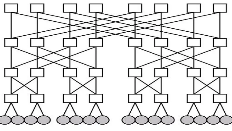
2.1. Intra-Chip Network
©2014, IJCSMA All Rights Reserved, www.ijcsma.com 73
routers in the fat tree topology are connected to the inter-chip optical network by interface switches, and the bottom level routers are connected to processor. Several components are formed together and connected as cluster. A processor cluster includes four processor cores and uses an electrical crossbar in the concentrators to communicate. This hybrid approach takes power and performance advantage of short-range electronic network and long- range optical network. All the optical routers in the top level fat tree are grouped into router clusters and configured by a network controller which resides at the top level of fat tree. Since the optical loss of each path is different, RAICON adjusts the output laser powers in OE interfaces for different optical paths.
1)Routing Protocol
In RAICON, if there is need for communication within the same cluster, then the packets are transmitted totally in electronic domain through a crossbar. On the other hand, if a packet needs communication between various cluster means, the source concentrator will send an request to the network controller and tries to reserve an optical path. If the path is reserved successfully, the packet will be transmitted optically to the destination and the destination concentrator would finally switch it to the right core in the cluster through the local crossbar. In traditional optical circuit switching, a separate electronic network is used for path maintenance. In traditional method the control packets can be sent in optical domain but it needs an extra EO/OE conversions at each router along the path. RAICON design is different from above traditional methods. In RAICON separate network controller is used to configure all the available routers.
Figure 2 Intra-chip optical network
the path. If the path is available, network controller would reserve the path and also send a grant signal back to the source core.
If there is no path is available then the received request will be considered as failed request. Such failed requests will stay in the buffer present in the network controller until the path is available. Once the path becomes available then the source concentrator will receives a grant signal. After the grant signal, source concentrator can send out data propagating along the path reserved by network controller. After transmission is finished, a tear down signal will be sent from the core to the network controller to release the path. By considering the whole process it can be known that only a limited number of control signals need to be transmitted. RAICON can significantly reduce the collisions. These would help to improve the network performance and power efficiency.
2) Network Controller
The network controller is present at the top of fat tree. This network controller is responsible for the communication between source and destination. These network controllers take responsibility for requests arbitration and path configuration. Both the inter chip and intra chip networks communications are handled by these network controller. Initially, the network controller will select the candidate requests from the buffer present in it. Then, it will look for the path for each request according to the routing algorithm. After the path selection, the network controller will look for the collision in the path by checking the states of the links. In addition, it also checks that the selected paths would not collide with each other. Finally, the link states networks get updated based on newly added paths and provides the grant signal for the received requests. Assuming the number of cluster is n, the complexity of this algorithm is O(n log n), given that it checks n paths and the longest path of a request is composed of 2 log2 n links.
3) Routing Algorithm
In fat tree network the communication path is designed with various routers connected to each other. So in order to reach the destination the packets need not to travel all the routers or switches. Based on destination address the path can be made turn to reach the destination in either levels. Turnaround routing algorithm is adopted for fat tree network. Specifically, a packet is routed upwards from the source core until it reaches a router which is the common router for the destination core. It is then routed downwards to reach the destination. In this implementation, the path is only determined by destination information to further easy the network controller. In order to balance the network link utilization, we use shuffling technology to find the path. Formally, each router in the upward path in level i checks the packet destination. If the (i − 1)th bit of the destination is 0, we select
the left path, otherwise the right path. The downward path is then fixed automatically because of the property of fat tree. Network controller chooses the path based on this routing algorithm, and configure the routers for data transmission.
4) Optical Router
Optical routers are based on two basic switching elements, including the parallel and crossing types. As shown in Figure 3, both of the two switching elements consist of two waveguides and one micro resonator (MR). The Micro Resonator resonance wavelength can be controlled by electrical voltage by control unit.. When the wavelength of input light and resonance wavelength are equal then signal would be diverted to another waveguide and propagate to the drop port. Otherwise, it would propagate directly to the through port. There may be different MRs available with different resonance wavelengths, and each kind of MR can control and pass corresponding light signals without affecting light in other wavelengths. RAICON transmits payload data signals and control signals in different wavelengths as λ0 and λ1 separately.
©2014, IJCSMA All Rights Reserved, www.ijcsma.com 75
Figure 3 Two basic switching elements
In Figure 4, the switching fabric in OTAR router in a cluster is shown, in which the switching function for optical data signals is in wavelength λ0 . The routing functions can be made by turning on/off corresponding MRs
in order to obtain various wavelengths. The main concept of this design is to minimize the number of waveguide crossings. Based on the routing algorithm, the routing is achieved in this router andthe path is selected and
appropriate micro resonators are made turned on and off. The routers present in each clusters are different from each others. The right router is attached with a control signal receiver. The MR with resonance wavelength λ1 will
provide the path for the control signals from network controller to a router control unit. The received control information would be interpreted to configure all MRs in this cluster with p a r t i c u l a r resonance wavelength. After MRs configuration, path is setup for payload data signals in d i f f e r e n t wavelength. Normally the control signals are transmitted with on wavelength and the data payloads are transmitted with the off wavelength. Top level routers are also attached with MRs in resonance wavelength λ1, responsible for receiving control data from source
concentrators and sending out control data to destination concentrators and clusters.
Figure 4. Optical Turn Around Router (OTAR)
2.2.Inter-chipNetwork
The inter-chip network connects all the intra-chip networks by means of optical bus. In RAICON, an optical bus with some arbitration is designed (Figure 5). Network controllers collaboratively arbitrate the optical bus and manage their own intra-chip network resource for inter-chip communications. Normally bus-based communication architectures are considered to have limited scalability, but due to their viable low-cost choice for systems with a moderate number of chips still they are used in inter chip process.. RAICON’s inter-chip network consists of two kinds of buses. They are termed as an optical data bus and an optical control bus. Data communications between chips are done by means of data bus, and the control bus helps network controllers to cooperate with each other during bus arbitration.
Figure 5. Inter Intra chip arbitration concept
1)
Optical Data Bus
In RAICON’s inter-chip network, the number of data bus channels is based on the number of routers present in the top level router. Each data bus channel is composed of a on-chip silicon waveguide, a polymer waveguide embedded on PCB board, and optical connectors which connect on-chip waveguides with on-board waveguides. The bus channel presented here is considered to be a bidirectional and half-duplex, that means at a time either one transmission can be made not two way communication at a same time. If we consider there are 64 cores in the fat tree then it requires only 16 data bus for communication N o r m a l l y intra-chip network and optical data bus channels are connected by means of an interface switch as said in architecture. The interface switch is designed with MRs and waveguides. Data signals can be sent to the bus in either direction depending on which MR is powered on. A important feature of the designed optical data bus is that a single data channel can be used by multiple chips simultaneously. Single data channel can be divided into multiple sections using the unidirectional property of optical signals by the interface switch, and each section can operate independently. The distributed priority arbitration can utilize this feature to reduce data collisions and improve performance.
2 )
Optical Control Bus
©2014, IJCSMA All Rights Reserved, www.ijcsma.com 77
controllers. It allows a network controller to broadcastcontrol signals. In general MR is used to inject control signals into the control bus, and some branch segment is used to eject control signals. Y-branches can be used here. It is designed with different split ratio.
3)
Network Protocols
Inter-chip communications require both the intra-chip and inter-chip networks, and are managed collaboratively by the network controllers. When a processor core wants to communicate with another core on a different chip, initially it sends a request to the network controller through a concentrator, which is the same as an intra-chip communication. After receiving the request, the network controller will broadcast the request with destination address to the network controller on the destination chip. The source and destination network controllers will simultaneously start to reserve an on-chip up- link path and down-link path respectively. For inter chip communication also same algorithm which is used for intra chip can be implemented. Network controllers will broadcast successful path reservations on the control bus. When there is an available path for both inter and intra chip communication,, network controllers will reserve a data bus channel and sends a grant signal to the source processor. After receiving the grant signal, source processor will starts to transmit packets immediately. Upon finishing the data transmission, a tear down signal is sent from the source core to the source network controller, which in turn broadcast it to the destination controller. All network controllers will update their status buffers based on received information and after the completion of transmission it releases path.
3. Arbitration Mechanisms
An arbiter is a logical element which is used to select the order of access to a shared resource or for a communication. An arbiter normally employs a scheduling algorithm to decide which one on several requestors would be serviced first. Arbiter provides arbitration between several requests that are competing for access path for communication. Thus an arbiter is essential to determine the resource sharing among different requesters. Properly designed arbitration policies are implemented to provide the permission for the scheduled results. The arbitration policy refers to the algorithm or logic by which the arbiter decides to give the grant or access to the communication path for the requester when multiple sources request the network controller simultaneously. The arbitration policy also decides what to do when none of the masters are accessing the bus.
3.1 Round Robin Arbitration
The round robin arbitration is an arbitration mechanism which employs a simple time slice scheduling, allowing each requestor an equal share of the time in accessing a memory or a limited processing resource in a circular order. A round robin arbiter allows every requester to take a turn in order. The advantage of the round robin arbitration is that the shared resource can be accessed evenly among different concentrator. It doesn’t give special priority to more important request.
3.2 Priority Arbitration
To overcome of the drawback of Round Robin and fixed Priority algorithm, a new arbitration mechanism with priority is introduced. In Fixed Priority arbitration and Round Robin Arbitration, there is no possibility to adjust the priority of the requesters, when they access the same node simultaneously. In this kind of Priority Arbitration, the default priorities of the requesters can be changed during the run time. The changed priority will override the default priority.
4. Conclusion
elements is implemented in fat tree topology. The switching element provides the efficient routing path based on routing methodology. The network controller on each chip manages the communications based on designed arbitration mechanism.
References
[1] D. A. B. Miller, 1997 “Physical reasons for optical interconnection,” Special Issue on Smart Pixels, International Journal of Opticalelectronics, vol. 11, no. 3, pp. 155–168.
[2] H. Gu, J. Xu, and W. Zhang, 2009 “A low-power fat tree-based optical network-on-chip for multiprocessor system-on-chip,” in DATE, pp. 3–8.
[3] N. Kirman, M. Kirman, R. K. Dokania, J. F. Martinez, A. B. Apsel, M. A. Watkins, and D. H. Albonesi, 2006 “Leveraging optical technology in future bus-based chip multiprocessors,” in MICRO 39: Proceedings of the 39th Annual IEEE/ACM International Symposium on Microarchi- tecture. Washington, DC, USA: IEEE Computer Society, pp. 492–503. [4] D. A. B. Miller, 1997 “Physical Reasons for Optical Interconnection,” Special Issue on
Smart Pixels, Int. J. of Optoelectronics, vol. 11, no. 3, pp. 155-168.
[5] I. O’Connor, F. Mieyeville, F. Gaffiot, A. Scandurra, and G. Nicolescu, 2008 “Reduction methods for adapting optical network on chip topologies to specific routing applications,” in Proc. Design of Circuits and Integrated Systems (DCIS).
[6] A. Shacham, K. Bergman, and L. P. Carloni, 2008 “Photonic networks-on-chip for future generations of chip multiprocessors,” IEEE Trans. Comput., vol. 57, no. 9, pp. 1246–1260.
[7] M. J. Cianchetti, J. C. Kerekes, and D. H. Albonesi,2009 “Phastlane: a rapid transit optical routing network,” in ISCA, pp. 441–450.
[ 8] Rajeev K. Dokania and Alyssa B. Apsel,2009 “Analysis of Challenges for On-Chip Optical Interconnects,” Great Lakes Symposium on VLSI, pp. 275-280.
[9] ] J. Xu, W. Wolf, J. Henkel, and S. Chakradhar, 2006“A design methodology for application-specific networks-on-chip,”
ACM Trans. Embed. Comput. Syst., vol. 5, no. 2, pp. 263–280.
[10] W. Dally and B. Towles, 2001 “Route packets, not wires: on-chip interconnec- tion networks,” in Design Automation Conference, Proceedings, pp. 684–689.
[11] G. Van Steenberge, P. Geerinck, S. Van Put, J. Van Koetsem, H. Ot- tevaere, D. Morlion, H. Thienpont, and P. Van Daele, 2004 “MT-compatible laser-ablated interconnections for optical printed circuit boards,” Light- wave Technology, Journal of, vol. 22, no. 9, pp. 2083–2090.
[12] S. H. Hwang, M. H. Cho, S.-K. Kang, H.-H. Park, H. S. Cho, S.-H. Kim, K.-U. Shin, and S.-W. Ha, 2006 “Passively assembled optical interconnection system based on an optical printed-circuit board,” Photonics Technology Letters, IEEE, vol. 18, no. 5, pp. 652–654.
[13] A. Apsel, Z. Fu, and A. Andreou, 2004 “A 2.5-mw SOS CMOS optical receiver for chip-to-chip interconnect,”
Lightwave Technology, Journal of, vol. 22, no. 9, pp. 2149–2157.
[14] F. Doany, C. Schow, R. Budd, C. Baks, D. Kuchta, P. Pepeljugoski, J. Kash, F. Libsch, R. Dangel, F. Horst, and B. Offrein, 2008,“Chip-to- chip board-level optical data buses,” in Optical Fiber communica- tion/National Fiber Optic Engineers Conference,OFC/NFOEC
2008. Conference on, Feb. 2008, pp. 1–3.