Published online November 14, 2014 (http://www.sciencepublishinggroup.com/j/jeee) doi: 10.11648/j.jeee.20140204.11
ISSN: 2329-1613 (Print); ISSN: 2329-1605 (Online)
LabVIEW based design implementation of M-PSK
transceiver using multiple Forward Error Correction coding
technique for Software Defined Radio applications
Nikhil Marriwala
1, Om Prakash Sahu
2, Anil Vohra
31
Electronics & Communication Engineering Department, University Institute of Engineering and Technology, Kurukshetra University, Kurukshetra, India
2
Electronics & Communication Engineering Department, National Institute of Technology, Kurukshetra, India
3
Electronics & Science Department, Kurukshetra University, Kurukshetra, India
Email address:
[email protected] (N. Marriwala), [email protected] (O. P. Sahu), [email protected] (A. Vohra)
To cite this article:
Nikhil Marriwala, Om Prakash Sahu, Anil Vohra. LabVIEW Based Design Implementation of M-PSK Transceiver Using Multiple Forward Error Correction Coding Technique for Software Defined Radio Applications. Journal of Electrical and Electronic Engineering.
Vol. 2, No. 4, 2014, pp. 55-63. doi: 10.11648/j.jeee.20140204.11
Abstract:
Software-Defined Radio (SDR) is an enabling technology which is useful in a wide range of areas within wireless systems. SDR offers a perfect solution to the problem of spectrum scarcity in wireless communication. With the significant increase in the demand for reliable, high data rate transmission these days, a different number of modulation techniques need to be adopted. The main objective of this paper is to design and analyze an SDR based M-Phase Shift Keying (PSK) transceiver using LabVIEW (Laboratory Virtual Instrumentation Engineering Workbench) and to measure the Bit Error Rate (BER) in the presence of Additive White Gaussian Noise (AWGN) introduced in the channel. Forward Error Correction (FEC) is used as a channel coding scheme in this paper. FEC codes are used where the re-transmission of the data is not feasible, thus redundant bits are added along with the message bits and transmitted through the channel. This paper describes the fundamental concept for the design & development of an SDR -based transceiver simulation model under PSK Scheme & analyses the performance of two Forward Error Correction channel coding algorithms namely the Convolution and the Turbo Codes. In this paper we have shown that how fast and effectively we can build a PSK transceiver for interactive Software Defined Radio. With the help of this design we are able to see and prove that data errors can be minimized using coding techniques, which in turn improves the Signal to noise ratio (SNR).Keywords:
Software Defined Radio, Bit Error Rate, Additive White Gaussian Noise, Phase Shift Keying, Signal-To-Noise Ratio, Forward Error Correction1. Introduction
The term Software Defined Radio refers to reconfigurable or reprogrammable radio that shows different functionality with the same hardware. The entire functionality of the SDR can be defined in software [1]. The aim of this paper is to simulate SDR for next generation wireless communication systems by using the M-PSK modulation technique in LabVIEW.
SDR provides an alternative to systems such as the third generation (3G) and the fourth generation (4G) systems [2]. A Complete hardware based system has many limitations. SDR technology provides many benefits including increased interoperability, reduced cost, and improved life cycle for
In this paper, the software simulator of the PSK transceiver has been designed using LabVIEW. PSK is chosen to be the modulation scheme of the designed interactive Software Defined Radio system as this modulation scheme is widely used for transmission of data for various applications over band pass channels such as paging systems and Cordless, Telephone-line modems, Caller ID, Microcomputers, Radio control etc. A PSK, SDR which is fully implemented, will have the ability to navigate over a wide range of frequencies with programmable channel bandwidth and modulation characteristics [8, 9]. The role of modulation techniques in an SDR is very crucial since modulation techniques define the core part for any wireless technology [10, 11].
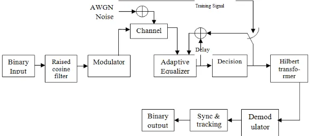
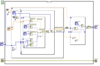
The aim of this design is to implement interactive Software Defined Radio system in a shorter time and provide a cost effective solution compared to other text-based programming languages [12, 13]. With the help of this design we will be able to see and prove that data errors can be minimized using FEC coding techniques, which in turn improves the Signal to noise ratio (SNR). This interactive design of SDR will also help understand and analyze how the signal can be recovered with very less probability of error and which FEC codes are the best suited for transmission using M-PSK modulation scheme. The general Block Diagram of a generic Digital transceiver is shown in Figure 1.
Figure 1. Block Diagram of a Generic SDR Transceiver.
2. Phase Shift Keying Transceiver
(M-PSK)
In This paper, digital modulation scheme Phase shift Keying is used as a modulation scheme for the SDR transceiver. PSK has dynamic characteristics of the carrier signal with respect to time and this alteration results in a sine gesticulate in a divergent phase, amplitude or frequency. This results in, contrasting "states" of the sine curve are referred to as symbols which represent few digital bit ornamentation. The building blocks of the PSK transceiver
system are stated in this section. This system has two parts: transmitter and receiver. The Front Panel for a PSK transceiver with multiple Encode and Decode techniques is shown in Figure: 2.
The organization of this paper is as follows: In Section I Introduction for SDR is explained, Section II gives the implementation of M–PSK transceiver in LabVIEW, in Section III the PSK transmitter parameters are described, Section IV gives the BER Vs SNR comparison, Section V describes the simulation results of a PSK transceiver using LabVIEW and finally in Section VI we draw the Conclusions.
2.1. Message Source
In this design at the transmission end, pseudo noise (PN) sequences are generated which serve as our message signal. A PN Sequence Generator block generates a sequence of pseudorandom binary numbers using a linear-feedback shift register (LFSR). The LFSR is implemented using a simple shift register generator. Here, the PN sequence is generated with a five-stage LFSR structure, whose connection polynomial is given by
h (D) = 1 + D2
+ 5
D (1)
where D denotes delay and the summations represent modulo 2 additions. The sequence generated by the above equation has a period of 31(=
2
5 – 1) as shown in Figure: 3. Two PN sequence generators are used in order to create the message sequences for both the in-phase and quadrature phase components. Note that frame marker bits are inserted in front of the generated PN sequences.Figure 3. Message Source VI.
2.2. Source Encoder
The source encoder is to improve efficiency by reducing redundant bits, compressing the digital sequence into a more competent symbol for transmission.
2.3. Pulse Shaped Filter
The purpose of pulse shaping is to make the transmitted signal better suited to the communication channel by limiting the effective bandwidth of the transmission. By doing this ISI caused by the channel can be controlled before modulation [16]. The raised cosine filter is one of the pulse shaping filter as shown in Figure: 4. It is used in digital modulation due to its ability to minimize Intersymbol
interference. Its name stems from the fact that the non-zero portion of the frequency spectrum of its simplest form (β = 1) is a cosine function, ‘raised’ up to sit above the f (horizontal) axis.
The raised-cosine filter is an implementation of a low-pass Nyquist filter, i.e., one that has the property of vestigial symmetry. This means that its spectrum exhibits odd
symmetry about , where T is the symbol-period of the communications system.
and characterized by two values; β, the roll-off factor, and T, the reciprocal of the symbol-rate.
2.4. PSK Encoder
Figure 5. Convolution Encoder VI.
The channel encoder is to improve reliability by adding redundant bits to the compressed information in order to control the errors offered by channel impairments. Convolution Encoder is a Finite State Machine (FSM), processing information bits in a serial manner. In this case we have implemented ½ rate convolution Encoder. Shift Registers are used through which data shifts in and out linearly. They have rather good correcting capability and perform well even on very bad channels (with error probabilities of about (10-3). Convolution Encoder Performs Convolution of the input stream with encoders impulse responses. Mathematically, it is written as
k i k
j k j
i h x
y −
∞
=
∑
=
0
(2)
where x is an input sequence, yj is a sequence from output j
and hj is an impulse response for output j. Convolution Encoder VI is shown in Figure:5.
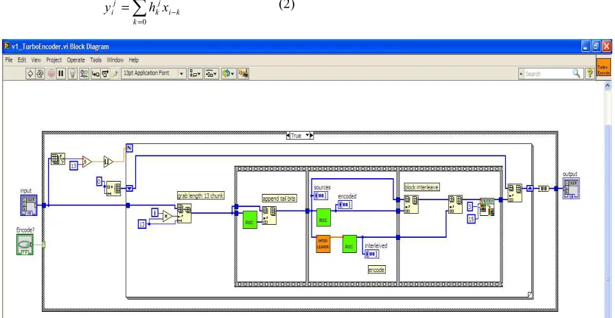
In this design we have used the Turbo Encoder as shown in Figure: 6 which works by using two Convolutional Encoders. One encoder receives the data to be sent and the other receives an interleaved version of the data to be sent. The convolutional encoders are identical and are rate 1. Each has 3 linear shift registers with a feedback loop. The original data, the output from encoder 1, and the output from encoder 2 are then interleaved together before being transmitted.
2.5. PSK Modulator
Figure 7. PSK Modulator Vi.
The PSK modulator converts the input bit stream into an electrical waveform suitable for transmission over the communication channel. In this design we have used the Modulator to minimize the effects of channel noise, also to match the frequency spectrum of the transmitted signal with channel characteristics, and to provide the capability to multiplex many signals as shown in Figure: 7.
The output of the raised cosine filter is then used to build a complex envelope. The data bits are transmitted by shifting the frequency of a continuous carrier in a binary manner to one or the other of two discrete frequencies. One frequency is designated as the “mark” (1) frequency and the other as the “space” (0) frequency.
2.6. Time Varying Channel
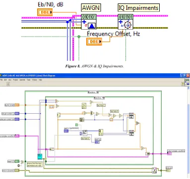
Figure 8. AWGN & IQ Impairments.
To be able to observe the adaptability of the system, a time-varying channel is added. The noise source, which is the Additive White Gaussian Noise (AWGN), is passed through the channel before it is added to the input signal. The channel is Gaussian in nature because its probability density function can be accurately modeled to behave like a Gaussian distribution and it is called white as it has a constant power spectral density. The characteristic of the channel is varied with time by swinging the filter pass band from 100 to 900 Hz. Figure: 8 shows the time varying channel with the AWGN noise source. Additive White Gaussian Noise is used to generate zero mean with uniform spectral density and adds it to a complex baseband modulated waveform. The VI shown in Figure:9. computes, generates, and adds the appropriate amount of AWGN to a complex-valued input signal, given a desired output Eb/N0 [10,11,12]. For true AWGN, the I and Q components of the additive noise must be uncorrelated. We accomplish this by using two separate Gaussian noise generators independently seeded. The user has the option of providing a seed in the event that they want to generate deterministic white Gaussian noise.
2.7. PSK Demodulator
PSK demodulation is the process of recovering the original message from the information bearing waveform produced by the modulation is accomplished by the demodulator. Demodulates the modulated complex baseband waveform & returns the time aligned oversampled complex waveform, demodulated bit stream. This step attempts to remove carrier & phase offset by locking to the carrier signal.
Viterbi decoding is an optimal (in a maximum-likelihood sense) algorithm for decoding of a Convolution code as this simplifies the decoding operation [17]. The decoder is a Viterbi decoder which then solves for the global optimum bit sequence. The algorithm updates a path cost as it steps through each stage of the possible output sequences. At each state, it also calculates the likelihood of entering each possible new state based on the cost of the previous state. The algorithm then needs two additional zero bits after every sequence in order to force the encoder back into the zero state and to assume that the encoder ends at the all zero state. These two tail bits represent a fractional loss rate between the coded and that of uncoded bit sequence. The Viterbi Decoder VI is shown in Figure: 10.
Figure 10. Viterbi Decoder VI.
Turbo Decoding used in this system as shown in Figure. 11. Works by using a set of maximum aposteriori probability (MAP) decoders. When the data is received, it is deinterleaved back into the three streams which were sent from the transmitter:
1. Original Data
2. Output from Convolutional encoder 1 3. Output from Convolutional Encoder 2.
Decoders then work together to converge on a solution: the most likely original bit sequence.
Figure 11. Turbo Decoder VI.
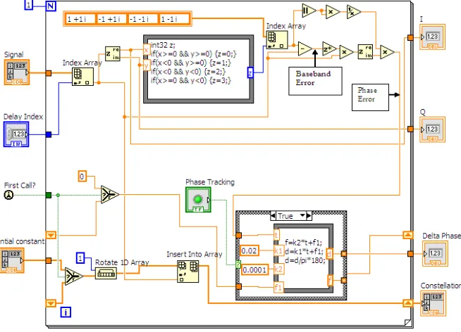
2.8. Sync & Tracking VI – Frame Synchronization Mode
Sync & Tracking VI is used for Frame synchronization and Phase/Frequency tracking. Synchronization is the act of synchronizing, i.e. concurrence of events with respect to time. In VI shown in Figure: 12 the input samples are passed through Complex Queue Pt By Pt VI, which creates a data queue of complex numbers to obtain beginning of frame. A case structure is not executed until the queue is completely filled. Extra 16 bits are added due to delays related to filtering operations in transmitter. A counter is used to count number of samples filling up the queue (as loop count VI). A Boolean (sync) is a primitive data type that can have one of
two values: TRUE or FALSE. The initial value of the local variable, which is denoted by Sync, is set to true to execute the frame synchronization. Then, it is changed to false within the case structure so that it is not invoked again. The other two local variables, Initial Const and Delay Index, are used as the inputs of the phase and frequency tracking module. The queue length is chosen to be 51 in order to include the entire marker bits in the queue. This length is calculated as under: 31[(one period of MLS sequence) + 2×10 (frame marker bits)]. The sync and tracking VI for the frame synchronization mode is shown in Figure: 12.
3. PSK Transceiver Parameters
Transmitter filters: Transmitter filter defines the type of
band-limiting filter employed at the transmitter for pulse shaping the symbols output by the modulator. In this design the user has the option to choose any of the varieties of the
filters from the given filters Raised cosine (Nyquist), Square-root raised cosine, Gaussian filters as depicted through Table: 1. Thus, this design makes it a unique SDR where the user has the option to select the required filter and see that which filter gives the minimum BER.
Table 1. Simulation Parameters.
Sl. No. Parameters That can be Decided by the User Values Taken by the user
1 PN sequence order 15 or any Value
2 Eb/No 80 dB or any Value
3 Message symbol 1000 or any Value
4 Transmission B.W (BT) 0.5 or any Value
5 Symbol Phase Continuity Continuous
6 PSK frequency deviation (Hz) 25KHz or any Value
7 Filter used Gaussian, Root Raised Cosine Filter, Root Raised Cosine Filter
8 Symbol Rate 100.00 KHz or any Value
9 Eb/No Sample 5 or any Value
10 Sample per symbol 16 or any Value
11 Modulation Index 0.5 or any Value
12 BER vs Eb / No (without filter) None
Raised cosine Filter: The raised cosine filter is one of the
most common pulse-shaping filters in communications systems. In addition, it is used to minimize inter symbol interference (ISI).
Root Raised Cosine Filter: The root raised cosine filter at
low frequency produces a frequency response with unity gain and complete at higher frequencies.
Gaussian filter: The Gaussian pulse-shaping filter reduces
the levels of side-lobes of the PSK & GMSK spectrum.
4. Bit Error Rate (BER) &
Signal-to-Noise Ratio (SNR)
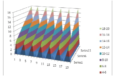
Figure 13. BER Vs Eb/N0(db) (4,8,16,32,64,128,256 bit FSK) Output Results
for Convolution coding.
Bit Error Rate (BER): In this section we discuss the BER
Vs the SNR achieved for different M-PSK in a noisy channel for both the Convolution and Turbo coding. The bit error rate (BER) is the number of bit errors divided by the total number of transferred bits during a considered time interval. BER is a unit less performance measure which is often expressed as a percentage (%). A pseudorandom data sequence (15) is used for the analysis in this design. The BER parameter represents the current operating BER of a
specific modulation type and in this design the modulation scheme selected is M-PSK. This value depends on various channel characteristics, including the transmit power and noise level.
Figure 14. BER Vs Eb/N0(db) (4,8,16,32,64,128,256 bit FSK) Output Results
for Turbo coding .
5. Simulation Results & of PSK
Transceiver Using Labview
In this section we describe the simulation results of M- PSK transceiver system for a noisy channel. BER Vs Eb/N0(db) for (4,8,16,32,64,128,256 bit PSK) has been given
SNR, the BER achieved is extremely small. With the help of this design we can also show that how fast and effectively we can build a PSK transceiver for Software Defined Radio.
6. Conclusion
In this section we discuss the simulation results of the M-PSK transceiver VI for noisy channel. From the results it becomes clear that the wireless system designed based on PSK technique provide high data rate and SNR. This can be very clearly seen in terms of the BER Vs Eb/No output graph.
We can also see very clearly with these results that data errors can be minimized using coding techniques, which in turn improves the Signal to noise ratio (SNR) further, we can also say looking at the results that Turbo coding gives a much improved and better minimization of the data errors that the Convolution & Viterbi coding. The performance of M-level PSK systems ( 4,8,16,32,64,128,256) for additive white Gaussian noise channel has been evaluated and compared on the basis of the simulations in LabVIEW as shown in Figure 13 & Figure 14. In this paper we have shown that how fast and effectively we can build a PSK transceiver for Software Defined Radio. We have used the Graphical programming language LabVIEW for building a PSK transceiver system which consists of a message source, a pulse shape filter, a modulator on the Transmitter section and demodulator, a frame synchronizer, a phase continuity and frequency deviation on the Receiver section. With the help of LabVIEW an interactive Software Defined Radio system has been built in a shorter time as compared to other text-based programming languages. With the help of this design we are able to see and prove that data errors can be minimized using coding techniques, which in turn improves the Signal to noise ratio (SNR). Also we can say by looking at the results that Turbo coding gives a much improved and better minimization of the data errors than the Convolution coding. In the end, we can say that the signal can be recovered with very less probability of error in Turbo coding than in Convolution coding with the increase in the M (number of levels) at the destination.
References
[1] J. Mitola III,”Software Radios –Survey, Critical Evaluation and Future Directions,” in Proc. National Telesystems Conference, 1992, pp. 13/1513/23.
[2] Matthew N. O. Sadiku and Cajetan M. Akujuobi "Software-defined Radio: A brief Overview", IEEE Potentials Journal, October/November 2004, pg. 14-15.
[3] Wipro Technologies Innovative Solutions, Quality Leadership “Software-Defined Radio” White Paper: A Technology Overview, August 2002.
[4] Nikhil Marriwala, O. P. Sahu, Anil Vohra,: “8-QAM Software Defined Radio Based Approach for Channel
Encoding and Decoding Using Forward Error Correction”, Wireless Personal Communications, 1st May-2013, Springer US, 10.1007/s11277-013-1191-z.
[5] Nikhil Marriwala, O. P. Sahu, Ritu Khullar and Anil Vohra, “Software Defined Radio (SDR) 4-bit QAM Modem using LabVIEW for Gaussian Channel”CIIT International Journal of Wireless Communication”. March 2011.
[6] C. Berrou, A. Glavieux, and P. Thitimajshima. Near Shannon limit error correcting coding and decoding: Turbo codes. In Proceedings of the IEEE International Conference on Communications, Geneva, Switzerland, May 2003.
[7] W. Tuttlebee, Software Defined Radio: Baseband Technologies for 3G Handsets and Base Stations, John Wiley & Sons, 2004.
[8] Friedrich K. Jondral “Software-Defined Radio—Basics and Evolution to Cognitive Radio” (EURASIP Journal on Wireless Communications and Networking 2005:3, 275–283).
[9] N. KIM, N. KEHTARNAVAZ, and M. TORLAK LabVIEW-Based Software-Defined Radio: 4-QAM Modem Proceedings of ICASSP, vol. 2, 2006, pp. 985-988.
[10] Eric Nicollet and Lee Pucker, “Standardizing Transceiver APIs for Software Defined and Cognitive Radio”, www.rfdesign.com, February 2008,
[11] P. Burns, “Software Defined Radio for 3G”, Artech House, 2002. ISBN 1-58053-347-7.
[12] Amanpreet Singh Saini, “The Automated Systems For Spectrum Occupancy Measurement And Channel Sounding In Ultra-Wideband, Cognitive, Communication, And Networking” Master of Science in Electrical Engineering, August 2009.
[13] RituKhullar, Sippy Kapoor, Naval Dhawan, “Modulation technique For Cognitive Radio, Applications”, International Journal of Engineering Research and Applications (IJERA) ISSN: 2248-9622 www.ijera.com Vol. 2, Issue 3, May-Jun 2012, pp. 123- 125.
[14] Hiroyasu Ishikawa, “Software Defined Radio Technology for Highly Reliable Wireless Communications,” Wireless Personal Communications, 64 (2012), 461–72 dx.doi.org/10.1007/s11277-012-0596-4.
[15] P. Prakasam and M. Madheswaran, “Intelligent Decision Making System for Digital Modulation Scheme Classification in Software Radio Using Wavelet Transform and Higher Order Statistical Moments,” Wireless Personal
Communications, 50 (2008), 509–
28 ,dx.doi.org/10.1007/s11277-008-9621-z.
[16] Ying Chen and Linda M. Davis, “A Cross-Layer Adaptive Modulation and Coding Scheme for Energy Efficient Software Defined Radio,” Journal of Signal Processing Systems, 69 (2011), 23–30,dx.doi.org/10.1007/s11265-011-0644-4.