A Study on the Burn Pattern Experiments in Structure Fire
Gi-Dong Song
1, Man-Sung Hur
2,*, Hyun-Joo Lee
11
Department of Scientific Investigation, Chungnam National University, Daejeon, Korea.
2
Faculty of Fire and Safety, Woosong College, Korea.
Received 30 July 2017; received in revised form 10 August 2017; accepted 12 August 2017
Abstract
The fire has created tremendous damage, yet skilled fire investigators can read the fire patterns left by the fire.
Through the fire patterns interpretation and analysis, fire investigators should be able to determine exactly how and
where the fire or explosion started. Fire patterns can help the fire investigator trace fire movement back to the point of
origin. The origin and cause investigation for is attempting to determine the first material ignited, the source of ignition,
and how the two brought together to cause the ignition. The investigators should read the fire scene to establish the
area of origin. In this study, through burn pattern experiments, fire behavior in the compartment, fire pattern formation
mechanism, fire patterns reproducibility, fire patterns persistence through flashover and full room involvement
condition, fire scene reconstruction for fire origin determination, and other fire pattern’s temperature will be discussed
and analyzed in depth. Burn test was conducted to recognize and analyze fire patterns created in the phase of pre
flashover or post flashover in the compartment (container house). In addition, fire pattern experiments are designed to
test combustible material, including polyurethane foam with a lower thermal inertia or wooden chair with a higher
thermal inertia. During these experiments, through the thermocouple fire pattern’s temperature will be measured in the
stage of pre flashover or post flashover.
Keywords: burn pattern experiments, fire patterns persistence and reproducibility, thermocouple, pre and post-flashover
1.
Introduction
Fire investigators have relied on burn patterns as their basis for determining the fire origin. A burn pattern is the visible,
measurable physical change or identifiable shapes formed by a fire effect, or a group of fire effects. Fire origin determination is
largely a matter of fire pattern recognition and analysis [1].
This burn pattern experiment is to s how a new paradigm of fire investigation through burn pattern analysis on a basis of
scientific method which has been a tool to define the origin and cause of a fire.
In structure fire, burn pattern tests are to reproduce the burn patterns , such as V shaped pattern, U shaped pattern, inverted
cone pattern, clean burn, alligator char pattern, protected area and heat shadowing that were observed and identified in fire
scenes.
In addition, burn pattern tests are to analysis fire behavior and combustion characteristics of material in stages of fire
growth in compartment fire. Soot and clean burn are closely related to carbon from incomplete combustion and flame plume from
complete combustion[2].
These tests confirmed that fire patterns such as clean burn and V-shaped pattern persist during post flashover conditions,
as well as providing evidence of the evolution of these fire patterns, such as U-shaped pattern and Inverted cone pattern. The
most important finding from these burn tests were that patterns can provide substantial evidence for to determine accurately the
correct origin of a fire.
2.
Experimental Design
2.1. Burn pattern experiment process
This burn pattern experiments were conducted in a container house at industrial complex located in the suburbs of the
metropolitan city of Daejeon, South Korea.
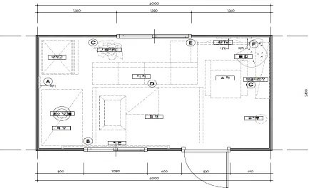
Fig. 1 The floor plan of compartment
2.2. Container house materials
Container steel panels are mostly composed of ‘SM20C’(carbon steel for machine structure) and container compartment is
4,000mm wide, 2,400mm long, 2,400mm high.
2.3. Surroundings conditions outside container house
Surroundings conditions outside container house include 24℃ of temperature, 42% of humidity, 3 m/s of wind speed, and
wind direction from SW to NE.
2.4. Experimental details
For the thermocouple measurement, fire investigator established 7 points and 29 points of temperature measurement (Fig. 1).
The materials for a fire source include the sofa and chair at the center of container house, the flat TV set on the wall, the book
shelves, the table of the kitchen sink, the refrigerator in the corner and the small size wastebasket on the floor of the compartment.
3.
Burn Pattern Formation and Its Analysis
3.1. Specific burn pattern created during fire test
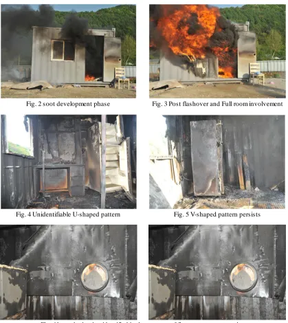
Go through The Initiation phase (Fig. 2) and go to The fully-developed phase (Fig. 3) in the clean burn.
Fig. 2 soot development phase Fig. 3 Post flashover and Full room involvement
Fig. 4 Unidentifiable U-shaped pattern Fig. 5 V-shaped pattern persists
Fig. 6 heat shadowing identified in the process of fire scene reconstruction
3.2. Burn pattern analysis
In pre-flashover phase U-shaped pattern and Inverted cone pattern were observed. In post -flashover phase V-shaped
pattern, clean burn, heat shadowing and protected area, and alligator char, po ur pattern, drop down pattern were formed.
3.2.1. U-shaped pattern
U-shaped patterns are created by the effects of radiant heat energy on the vertical surfaces , such as a wall. Actually,
U-shaped pattern can be formed by ignition occurred while mainly co oking or frying, reaching the ignition temperature. Therefore,
During this test, the U shaped pattern was observed on the interior wall of container house. From cooking oil ignition and
growth, the fire plume caused its upward current to create a U - shaped pattern in the stage of pre flashover. But in the phase of
post flashover or full room involvement, it should be noted to make it difficult or impossible for fire investigators to interpret and
identify the U shaped pattern. (Fig. 4)
3.2.2. Inverted cone pattern
Inverted cones are commonly caused by the vertical flame plumes of the burning volatile fuels not reaching the ceiling.
Inverted cone patterns are characterized by relatively short -lived fires and low HRR fires that do not fully evolve into
floor-to-ceiling flame plumes or flame plumes that are not vertically restricted by ceilings. At this experimental setting, in itial
inverted cone pattern cannot be well found and identified because initial burn pattern can be almost destroyed by the effects of
intense radiant heat through the post flashover or the full room involvement.
3.2.3. V pattern
The appearance of the V-shaped pattern is created by flames, convective or radiated heat from hot gases, and smoke within
the fire plume. The V-shaped pattern often appears as demarcation lines defining the borders of the fire plume and less heated
areas outside the fire plume. At this experiment, V-shaped pattern persists in the presence of an ignitable liquid through flashover
and full room involvement fire. (Fig. 5)
3.2.4. Clean burn pattern
Clean burn is found on noncombustible surfaces where there has been direct flame contact which burns off soot or smoke
deposits. Smoke deposits on surfaces are subject to oxidation. The carbon will be oxidized to gases and disappear from the
surface.
3.2.5. Drop down(fall down) pattern
The fire investigators should keep in mind that during the growth and spread of a fire, burning debris often falls to lower
levels, such as the floor and then burns upward from there. This is known as drop down (fall down).
Fall down can ignite other combustibles producing low burn patterns that can easily be confused with the area of fire origin.
3.2.6. Pour pattern
The pour pattern by liquid accelerant is the typical burn pattern identified in the arson fire scene. During burn test paint
thinners have been poured on the floor and wooden chairs in this compartment. Gasoline, kerosene, and paint thinner are the
most common fuels as an accelerant.
3.2.7. Alligator char pattern
As the burning continues and more volatiles are driven out of the wood, the char layer becomes deeper and splits and cracks
forming a char surface often described as 'alligatoring' that looks like the scales on an alligator's back. In some case alligator’s
pattern (large rolling blisters) was caused by the rapid intense movement of heat and flame. This condition may be associated
with the use of an accelerant. At experiment, paint thinner have been poured at wooden chairs on the floor of container house and
3.2.8. Heat shadowing
Heat shadowing results from an object blocking the travel of radiated heat, convected heat, or direc t flame impingement from
its source of the material on which the pattern is produced. Conducted heat, however, does not produce heat shadowing. This
heat shadowing (wall clock) was identified in the process of reconstructing the fire scene. (Fig. 6) It is believed that the wall clock
fell to the floor of the compartment due to the effects of flashover and full room involvement fire.
3.2.9. Protected area
Closely related in appearance to the resulting pattern of heat shadowing is a protected area. A protec ted area results from
an object preventing the combustion products from depositing on the material. The patterns produced by protected areas may
assist the fire investigators in the process of fire scene reconstruction during the origin determination by in dicating the location
of objects in their pre-fire locations. Therefore, heat shadows and protected areas may both provide valuable information or clues
to fire investigators.
3.2.10. 'Tear pattern’
Tear pattern was created during combustion experiments for the pattern penetration of horizontal surfaces in a upward
direction.
4.
Discussion and Result
4.1. Fire behavior in the compartment
The compartments or enclosures , such as container house, can represent any confined space which limits air supply. The
fire development stages of structure fire include ignition period, growth period, flashover, fully developed period, and decay
period [3]. Usually the fire growth period is defined as the pre-flashover stage, and the post-flashover phase includes the fully
developed period and the decay period. In most structure fires , it is only during the early growth stages that fuel is the limiting
factor in the development and spread of the fire and during this stage the fire is defined as fuel-controlled [4]. In
ventilation-controlled period, usually the stages of flashover or fully developed fire, fire growth is predominantly limited by air
(oxygen) available in the compartment. On the decay stage, the fire would be changed from ventilation controlled to fuel
controlled [5].
4.2. Fire patterns reproducibility and persistence
This experiment demonstrated that nine of the burn patterns can be created during the burn test in the container house. The
burn patterns reproduced during the combustion experiments include V p attern, U-shaped pattern, Inverted cone pattern, heat
shadowing, protected area, alligator char pattern, clean burn, pour pattern, drop down(fall down) and unique 'tear pattern'.
The fire patterns created at the early stages of fire growth may or may not p ersist through flashover and full room
involvement. Usually a V pattern persists in the presence of ignitable liquid as arson fire accelerant, even during post flashover
and full room involvement. Flashover sometimes creates new fire patterns. It should be noted that the flashover often destroy
and distorts or obscures the fire patterns at or near the area(point) of fire origin,making it difficult or impossible to identify the fire
4.3. Fire scene reconstruction
Protected areas have been shielded from combustion product, such as char and soot. Heat shadowing results from an object
blocking the travel of radiated heat, convected heat, or direct flame impingement from its source of the material on which the
pattern is produced. Conducted heat does not create heat shadowing. Heat shadowing can change, mask, or prohibit the
production of identifiable demarcation lines that may have appeared in that material. But patterns produced by the heat
shadowing may assist the fire investigators in the process of fire scene reconstruction during the fire origin determination. Heat
shadowing and protected areas can help the fire investigators reconstruct the pre -fire location of contents in the room.
5.
Conclusions
The fire patterns reproduced from this combustion experiments in compartment include nine of fire patterns , such as a U -
shaped pattern, protected area that can actually be identified at a fire scene. In the phase of the pre - flashover U-shaped pattern,
Inverted cone pattern were created, however, in the stage of post-flashover V-shaped pattern, clean burn, fall down, heat
shadowing and protected area, alligatoring, and pour pattern were produce d.
This burn test demonstrated that the fire pattern , such as V pattern persisting through flashover and full room involvement
condition in a compartment fire. On the other hand, U-shaped pattern no longer persists through post flashover and full room
involvement.
Once the area and possibly the point of origin is identified, the fire investigator should pinpoint the cause of fire or
explosion.
The created specific fire patterns' temperatures measured by the thermocouple range from 300℃ below at a U-shaped
pattern, Inverted cone pattern to 876℃ ~ 930℃ on V-shaped pattern, clean burn, fall down, heat shadowing and protected area,
and to 903℃ at alligatoring, and pour pattern.
References
[1] National Fire Protection Association, NFPA 921 Guide for Fire and Explosion Investigations, 2011.
[2] International Fire Service Training Association (IFSTA), Introduction to Fire Origin and Cause, 3nd ed. IFSTA Committee, 2003.
[3] D. D. H. John, Kirk’s Fire Investigation, 6th ed., Milwaukee: Brady, 2007.
[4] C. L. Tien, K. Y. Lee, and A. J. Stretton, The SFPE handbook of fire protection engineering, 4nd ed. Quincy: NFPA Inc., 2008. [5] V. Babrauskas, “The SFPE handbook of fire protection engineering,” 4nd ed. Quincy: NFPA Inc., pp. 12, 2008.