*
Corresponding author: [email protected]
Parametric optimization of the cross-section and shape of the
longitudinal member in frontal impact
Dmitry Bogdanov,Yury Boldyrev, Pavel Cvetkov*, Oleg Klyavin, Ilya Davydov and Anatolii Smetankin
Peter the Great St. Petersburg Polytechnic University, 195220 St. Petersburg, Russian Federation
Abstract. The article considers the problem of optimal design of car body elements (longitudinal members) according to the chosen criteria. Both the questions of formulation of the optimization task and individual problems of its solution are studied. The mathematical statement of the problem is considered. Thus, the most attention is given to consideration of realisation of used numerical procedure of optimization. The system of numerical calculations is based on the most widely spread software systems for engineering analysis and design. The developed scripts on Python programming language are briefly considered. Results of optimization of longitudinal members of the car are given.
1 Introduction
Since the advent of digital computers, mathematical modelling technologies have played an increasing role in virtually all areas of engineering analysis and design in mechanical engineering. At the same time, the automotive industry, as one of the key and most high-tech branches of mechanical engineering, is one of the areas where such technologies are most actively and widely implemented[1]. At the same time, as in the development of any type of vehicles is the problem of creating a "safe" car is in the focus of attention. By "safe" we mean a car with active and passive safety. Let us explain the introduced concepts of safety. Active car safety[2-3] is a set of constructive decisions directed on prevention of failures. It includes measures maintenance of controllability and stability in motion, effective and reliable braking, reliable steering, sufficient visibility, effective performance of external and signal devices. Passive vehicle safety[4-8] is a set of design solutions that exclude or minimize the consequences of an accident for the driver, passengers and pedestrians. The solution to passive safety problems includes the use of "energy-effective" elements[9] in the front and rear of the car, i.e. such structural elements that are able to "dampen" external shocks to the maximum extent possible, as a consequence of impacts with moving and stationary objects. Other passive safety features include seat-belts, the leak tightness and protection of the fuel system and batteries, and the 'effective' hood in a sense, which is particularly relevant to pedestrian accident, the reliability of the bodywork and a number of other features.
In this paper we consider the problem of optimal design of one of the most important elements of the passive safety system, namely the longitudinal members
of the car, which are potentially one of the most "energy-intensive" elements of the structure.
Longitudinal members play a role in the car's structure as the power elements that strengthen the structures. We study the problem of choosing the best (optimal) longitudinal section in some sense as "energy-intensive" structural elements. It should be noted at once that during the design process it is necessary to satisfy simultaneously a number of criteria: the longitudinal members should not be completely crumpled, thus causing damage to the driver and at the same time should not be too rigid not to cause damage to the driver and passengers from seat-belts.
Thus, the problem of optimizing[10-11] the shape of the longitudinal member section is of vital importance, and taking into account the complexity of the task, it is important to build a procedure that implements an automated optimization process. The last is caused by that circumstance that usually at designing of the car even at the initial stage the process of designing has iterative character at interaction of groups of designers and engineers. The approach presented in article allows to reduce time of finding optimum cross-section.
2 Methods
ways to reduce the cost of model tests is a serious simplification of mathematical models that allows to reduce the time of unit calculation and increase the number of performed calculations for the same time[14-16]. Taking into account that relatively simple models are used in the calculations, one more important parameter, which allow to control the calculation process is the size of elements and type of finite elements of the model. This also includes the choice of dimensions and mesh parameters, which will be discussed below.
Let's briefly dwell the computing tools used in the work, which were implemented as a "bundle" of LS-Dyna and LS-Opt software and automated Pre/Postprocessing software system. The choice of Ls-Dyna was proved by its leading position for solving problems related to nonlinear fast processes in deformable media with complex rheological properties and for solving spatial dynamic nonlinear problems of contact interaction, i.e. for modelling crash - tests. Preporcessing program is used to modify the mesh, while Postprocessing is used for evaluation of crash-test results.
At the same time, the above mentioned bundle was not enough to build the required procedure of automation of the optimization process, and a number of modules - scripts in Python language were developed for the given case. One of them provided a parametric construction of the inner edges of the longitudinal member. The other one allowed to receive and generate a report for each crash-test coupled with Postprocessing. More details about the work of scripts will be described below.
2.1 Explicit dynamic formulation
Dynamic analysis is required in those problems where it is important to take into account the inertial properties of the structure and it is necessary to consider a fast-paced process with significant acceleration [17].
Since the problem is complex, let's consider briefly only the basic equations of dynamics of the considered system in the vector form, which have the following form:
Man+Cvn+Kun = fn (1)
where M, C, K are matrixes of masses, damping and stiffness of elements of dynamic system, fn is vector of external forces, un is movement, vn is speed, an is acceleration, n is time step in which nodal values are known.
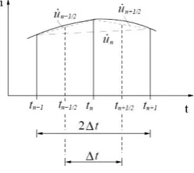
Fig. 1. Time discretization central difference scheme.
The problem is solved by an explicit method. The solution uses a central difference scheme[18], and the integration scheme comes down to the following:
(
)
2
1
1 1 − +−
∆
=
n nn
u
u
t
v
(2)where Δt is the time step and the node values with the index n are known. With this expression you can get an expression for a, expressed in terms of u:
1 1 1 1 2 2 1 1 2 1 1 ( ) ( ) 1
( 2 )
( )
n n n n
n
n n
n n n
u u u u
a v v
t t t t
u u u
t + − + − + − − − = − = − = ∆ ∆ ∆ ∆ = − + ∆ (3)
If expression (3) and (2) are subtracted to expression (1), the expression is converted to:
1 2 2 1 1 ( ) 2
( 2 ) ( )
2 n
n n n
M tC u
t
t f t K M u M C u
+ − + ∆ = ∆ = ∆ − ∆ − − − (4)
It is important to determine the time step when solving the dynamics problems. The time step for a crash-test simulation task is limited by the time it takes for the shock wave that is generated by the load to be transmitted through the smallest element of the grid:
c d t= min
∆ (5)
2.2 Initial state
Fig. 2. Vehicle Impact Test Scheme for the non-deformable barrier according to Euro NCAP.
The weight of the model, including point weights, was set at 980 kg. The elastic plastic material model
MAT 24 MAT_PIECEWISE_LINEAR_PLASTICITY[19-20] is
used: piecewise linear model of the material with any dependence between stress and deformation (Fig. 3). The whole model consists of shell elements. Shell elements are 3 or 4-node three-dimensional shell elements with the ability to determine the membrane properties. The initial thickness of the optimized longitudinal members is 2 mm. On Fig. 4 - 6 the linear dimensions and finite element grid of the model are shown.
Fig. 3. Stress deformation dependence diagram.
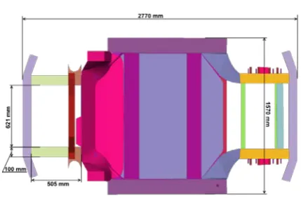
Fig. 4. Linear dimensions of the finite element model (top view).
Fig. 5. Linear dimensions of the finite element model (left view).
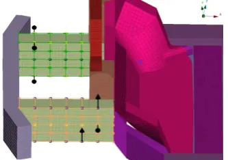
Fig. 6. The finite element mesh of the calculation model.
The table below shows the characteristics of the longitudinal member material.
Table 1. Material Specifications.
Name [units] Value
Density, ρ [kg/m3] 2700
Young's module, E [GPa] 70
Poisson's ratio, ν 0.3
One of the important problems with the numerical procedure was the choice of the size of the elements of the dimensional calculation grid. The range of values from 5 to 100 mm was considered, and the values of the convergence rate were studied. According to the data of convergence and calculation time, the size of 20 mm was chosen.
As already noted, in order to optimize the shape of the cross section of longitudinal members a Python script has been written, allowing you to place and paste the inner edges into the longitudinal members. It is possible to choose the number and type of edges (vertical or horizontal). Ribs are evenly distributed depending on their number.
To modify the geometry of longitudinal members, morph boxes with the possibility of deformation were created. Morph[21] is a special tool in the Preprocessing designed for simple change of grid geometry and represents a closed volume (morph box) in which nodes and/or grid elements are placed. Changes to the morph box (relocation of its node elements located on the edges) result in interpolation of the elements inside the morph box. In this way, morph boxes make it possible to easily change the geometry of the grid without any modification of elements.
−loading of a pre-created horizontal/vertical edge (copy of the longitudinal member wall);
−copying the edges according to the required quantity;
−splicing the edges between each other and the longitudinal member itself;
−placing the obtained structure (mesh) in morph boxes;
As a result of the work of the script, we get longitudinal members with the inner ribs and the possibility of changing their geometry with the help of morph boxes. In Fig. 7 shows possible movements of morph box points in the current parametric optimization is demonstrated.
Fig. 7. Morph boxes, node elements and possible movements of node elements.
During the optimization procedure the following parameters and their ranges were selected:
−thickness of ribs and longitudinal members: 2 - 4 mm (SPAR__RIBS_T);
−number of vertical ribs: 0 - 2 pcs (RIBS_V); −number of horizontal ribs: 0 - 4 pcs (RIBS_H); −moving the upper and lower points of morph boxes in the Z-direction: -50 - 50 mm (UPPER_UPDOWN, BOTTOM_UPDOWN);
−moving the upper, middle and lower points of morph boxes in the Y-direction : -50 - 50 mm (UPPER, MIDDLE, BOTTOM).
Since the process of optimal design was iterative, the script in Python language was used for its effective implementation, which allows to get the results necessary for optimization when interacting with Postprocessor. Input data are *.binout files received as a result of calculation in Ls-dyna. As a result of the script operation, we get the output file containing the following data: car weight; model kinetic energy at the end of the calculation time; clip value of 3ms of point B (Fig. 6); maximum point B movement in X direction.
The following parameters were selected as optimization criteria[22-23]:
−mass;
−kinetic energy; −clip 3ms[24].
The FMVSS 208 - Clip 3ms (A3ms) rule criterion was used to estimate the peak deceleration value[25]. This criterion indicates that the peak acceleration value should last at least 3 ms. This requirement is justified by the methods of measurement during real-life research
and is supported by the assumption that slowing down the acceleration of a shorter duration has no effect on the brain[26].
Additional limitations in our task are:
−clip 3ms: 60 - 80 g (according to Euro NCAP)[27]; −movements along the X-axis: 650 - 800 mm.
3 Results and Discussion
As a result of optimization, the following correlation matrix was obtained in Ls-opt[28] (Fig. 8). This matrix shows the impact of one parameter on the other and how strongly its change affects it (+1 - strict direct connection, -1 - strict reverse connection, 0 - no connection).
Fig. 8. Parameters and results correlation matrix.
The main result of the work is the developed algorithm of forming the internal section of longitudinal members, focused on a specific task (structure). The main difference from the methods traditionally used earlier is the possibility of parametric generation of inner ribs. In the process of using the optimization procedure some more effective variants of the design were found. By effective variants we understand the variants satisfying the required restrictions and showing better results with respect to the criterion of kinetic energy, as well as the possibility of technologically realizing the obtained geometry of longitudinal members. Fig. 9 below shows some effective variants. Fig. 10 shows the acceleration graphs of point B and Clip3ms values for the different longitudinal members variants.
Fig. 10. Acceleration graphs and 3ms values.
The table below shows the results of the calculation of the initial geometry of longitudinal members (Figs. 4-6) and the variants, whose cross sections were presented above.
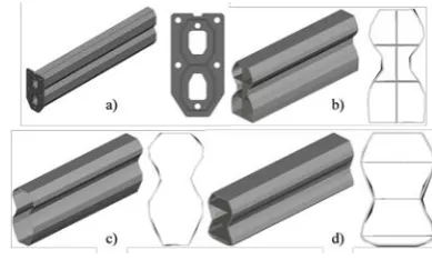
One of the efficiency indicators of the algorithm was to obtain a longitudinal member geometry similar to the known longitudinal members of Tesla Model S. These longitudinal members show high quality of their work in the form of 5 stars Euro NCAP and 14.4 points in frontal impact. Several examples of the obtained geometry are shown in Fig. 11 below. Fig. 12 shows the acceleration graphs of point B and Clip3ms values of different longitudinal member variants similar to those of Tesla Model S longitudinal members. In Table 3 below are the results of the calculations of the longitudinal members, the cross section of which was presented in Fig. 11.
Fig. 11. Some of the good variants, similar to the Tesla a)
original Tesla longitudinal member, b) Var. 5, c) Var. 6, d) Var. 7.
Fig. 12. Acceleration graphs and 3ms values, similar to the Tesla.
As can be seen from the results, the proposed algorithm allows optimizing the longitudinal members of the car for the specified sets of parameters.
4 Conclusions
The obtained results show the efficiency and effectiveness of the developed optimization algorithm. The obtained results are the most relevant at the initial stage of the car design development. The geometry obtained as a result of optimization is not ideal and requires improvement by designers, however, the proposed procedure in its first approximation is an effective solution to the problem of optimization.
The resulting optimization methodology, as well as scripts, is a working tool for the optimization of any closed section, which has the pipe-like shape and can significantly reduce the time spent in the development of a car.
This work was performed within the implementation of Federal Targeted Program for Research and Development in Priority Areas of Development of the Russian Scientific and Technological Complex for
2014-Table 2. Results table.
Variants Clip3ms (g) Displacement (mm) Kinetic energy (kJ) Mass (kg)
Initial 104.937 888.819 11936.638 980
Var 1 73.610 764.363 11004.611 987.016
Var 2 75.847 679.411 8235.427 988.339
Var 3 66.400 723.415 8664.315 988.572
Var 4 72.876 736.577 7086.786 988.381
Table 3. Results table.
Variants Clip3ms (g) Displacement (mm) Kinetic energy (kJ) Mass (kg)
Var 5 75.766 681.565 7446.470 981.533
Var 6 66.052 749.493 9005.944 982.496
2020, the project «Creation of Smart Digital Twin and Preproduction Prototype of Small-Size Urban Electric Car with ADAS 3-4 Level System» (Agreement № 05.578.21.0269, the unique project identifier is RFMEFI57818X0269).
References
1. A. Fürst and T. Vietor, Procedia CIRP 84, 605 (2019)
2. A. Weyssenhoff, M. Opala, S. Koziak, and R. Melnik, Transp. Res. Procedia 40, 119 (2019)
3. I. Peter, E. Fracchia, I. Canale, and R. Maiorano, Procedia Manuf. 32, 50 (2019)
4. W. Pawlus, K. G. Robbersmyr, and H. R. Karimi, Appl. Math. Model. 35, 5091 (2011)
5. E. Fechová, J. Kmec, A. Vagaská, and D. Kozak, Procedia Eng. 149, 263 (2016)
6. K. Brolin, I. Stockman, M. Andersson, K. Bohman, L.-L. Gras, and L. Jakobsson, IATSS Res. 38, 92 (2015)
7. A. Giampieri, J. Ling-Chin, W. Taylor, A. Smallbone, and A. P. Roskilly, Energy Procedia 158, 3381 (2019)
8. L.-X. Guo, H. Chen, and J.-L. Li, Procedia Eng. 15, 3046 (2011)
9. S.-L. Lin, B.-H. Huang, and F.-K. Chen, Procedia Eng. 81, 2198 (2014)
10. Yu.Yu. Boldyrev, Variational Calculus and Optimization Methods. Tutorial (St. Petersburg Polytechnic University Publishing House, 2016)
11. A. V. Porubov, I. D. Antonov, D. I. Indeitsev, and A. L. Fradkov, Mech. Res. Commun. 93, 124 (2018)
12. M. van Schijndel-de Nooij and J. Wismans, Int. J. Crashworthiness 13, 591 (2008)
13. Y. Men, G. Zheng, H. Z. Lu, and Z. Wang, in Lect. Notes Electr. Eng. (2013), pp. 349–360
14. V. M. Karbhari and X. Chaoling, Int. J. Crashworthiness 8, 471 (2003)
15. L. Peroni and M. Avalle, in Struct. Under Shock Impact IX (WIT Press, Southampton, UK, 2006), pp. 445–454
16. G. M. Nagel and D. P. Thambiratnam, Int. J. Impact Eng. 32, 1595 (2006)
17. S. T. C. Livermore, in Finite Elem. Anal. Predict. Eng. (2011)
18. C. O’Sullivan and J. D. Bray, Eng. Comput. 21, 278 (2004)
19. E. Nassiopoulos and J. Njuguna, Mater. Des. 66, 473 (2015)
20. M. Q. Nguyen, D. J. Elder, J. Bayandor, R. S. Thomson, and M. L. Scott, J. Compos. Mater. 39, 375 (2005)
21. D. Mohotti, M. Ali, T. Ngo, J. Lu, and P. Mendis, Mater. Des. 53, 830 (2014)
22. J. A. S. Freeman and D. Saad, Neural Networks 9, 1521 (1996)
23. R. F. Gunst, R. H. Myers, and D. C. Montgomery, Technometrics 38, 285 (1996)
24. H.-W. Henn, Teach. Math. Its Appl. 17, 162 (1998) 25. NHTSA, Fed. Regist. (2000)
26. J.-E. Kim, M.-H. Hsieh, P. C. Shum, R. S. Tubbs, and D. B. Allison, Obesity 23, 644 (2015)
27. Euro NCAP, October (2018)