PRELIMINARY MULTIDOMAIN MODELLING AND SIMULATION STUDY OF A
HORIZONTAL AXIS WIND TURBINE (HAWT) TOWER VIBRATION
I. lliyasu
1, I. Iliyasu
2, I. K. Tanimu
3and D. O Obada
41,4
D
EPARTMENT OFM
ECHANICALE
NGINEERING,
A
HMADUB
ELLOU
NIVERSITY,
Z
ARIA,
K
ADUNAS
TATE.
NIGERIA.
2D
EPT.
OFS
CI.
L
AB.
T
ECH.,
S
CHOOL OFA
PPLIEDS
CI.,
N
UHUB
AMAILIP
OLYTHECNIC,
Z
ARIA,
K
ADUNAS
TATE.
NIGERIA.
3
D
EPARTMENT OFM
ECHANICALE
NGINEERING,
F
EDERALU
NIVERSITY,
W
UKARI,
T
ARABAS
TATE.
NIGERIA.
E-mail addresses:
1iiliyasu@abu.edu.ng,
2iiliyasuishaya@gmail.com,
3terrytaninmu@yahoo.com,
4obadavid4@gmail.com
ABSTRACT
Renewable energy sources have gained much attention due to the recent energy crisis and the urge to get clean
energy. Among the main options being studied, wind energy is a strong contender because of its reliability due to
the maturity of the technology, good infrastructure and relative cost competitiveness. It is also interesting to note
that there are physical limits to the potential height of a wind turbine tower since the mechanical structure of wind
turbines are thus very flexible and tend to oscillate. This makes the design of wind turbines a demanding task. In
this paper, the oscillation of a wind turbine tower due to imbalance in the masses of the blades is modeled in
maplesim and the effect of the tower height on its oscillation was simulated. For a wind turbine with three rotor
blades, two of which have masses of 10 kg, a mass moment of inertia of approximately 20 kg/m
2and one of the
blades has a moment of inertia which is 1% less than the other blades. The simulation showed the most stable
system for the most energy capture for this case study to be a rotor speed of 5.5rad/s at a height of 10m. At this
angular frequency the deflection of the top of the wind turbine was approximately 1mm.
Keywords: Wind Turbine, Tower Oscillation, Maplesim, Modeling and Simulation.
1. INTRODUCTION
Structural dynamics is at the center of wind turbine tower design. Excessive vibrations can be caused by a wide range of environmental and mechanical sources and can lead to reduced component life due to fatigue, noise, and impaired public perception of system integrity [1]. The tower enables wind energy utilization at sufficient heights above the ground and also helps absorb and securely discharge static and dynamic stresses exerted on the rotor, the power train and the nacelle into the ground. Figure 1 shows a schematic tower for windmills and wind turbines and these mills and turbines powered by wind energy certainly have a long history. By the end of the eighteenth century, English and Dutch windmills had reached a high degree of sophistication. The new generation of megawatt horizontal axis wind turbines (HAWTS) spearheading the current surge in wind energy capacity are almost all mounted on tubular steel towers. Fashioned from steel plates, rolled to produce the required curvature and then
welded, they give technical perfomance, ease of maintenance, longevity and vitual elegance [2].
Figure 1:A Horizontal axis wind turbine(h indicating height of tower)
A wind turbine turning steadily has to endure many Nigerian Journal of Technology (NIJOTECH) Vol. 36, No. 1, January 2017, pp. 127 – 131 Copyright© Faculty of Engineering, University of Nigeria, Nsukka,
forces, static and dynamic, that are not directly concerned with the production of electricity. Static forces, for example, the load imposed by a steady wind on a stationary rotor, or the weight of a tower on its foundations may be easy to visualize. But more complicated are the effects of weight and wind shear on individual blades as they rotate. Non-cyclic dynamic forces, especially fluctuating wind forces acting on turbine blades and rotors, are the most awkward of all, both theoretically and in practice. Dynamic forces may set up unwelcome vibrations and in the long term cause fatigue and failure of mechanical components [2]
Tower vibration studies are important not only for the stresses they place on the towers themselves, but for unwanted aerodynamic effects a swaying tower has on blade performnace and for the stresses it transfers to other turbine components. Fatigue occurs in engineering materials subjected to repeated cyclic loads and eventually after millions of ‘cycles’ cause failure[2] . This is a case of structural damage.Although structural damage can happen to any structural component, the most common type of damage is rotor or blade damage and tower damage [3]. Extensive attention has been given to the structural health of blades as they are the key elements of a wind power generation system, and also because the cost of the blades can account for 15– 20% of the total turbine cost. It has been shown that the blade damage is the most expensive type of damage to repair and also has the greatest repair time [4]. Furthermore, rotating mass unbalance due to minor blade damage can cause serious secondary damage to the whole wind turbine system if prompt repair action is not taken and this can result in the collapse of the whole tower [5].
Several turbine simulators have been created to model the wind turbine shaft in laboratory studies. Some simulators are capable of dynamic simulations [6-8] while others are only capable of performing steady state simulations [9]. The simulator may only emulate the elements incorporated into the model. The simplest and most common approach is to use a basic steady state torque equation to calculate wind power and use this to determine the acceleration on the turbine inertia [9-11]. Many of the lab simulators reviewed [8-13] did not include the effects of horizontal wind turbine tower vibration, making these simulators unsuitable for studying issues that may arise due to these effects. The aim of this work therefore is to model the tower vibration of a horizontal axis wind turbine using Maplesim. This is to demonstrate how the vibration of a wind turbine tower as result of unbalanced rotor blades can be simulated and also to show how the effects of changes in some parameters at the design stage can be used to optimize design without any need for a physical
prototype.
2. SIMULATION STUDIES 2.1 Theory
The tower can be modeled as a cantilever beam with a tip mass subjected to a tip force. Based on the Euler-Bernoulli beam theory the deflection at the tip of a cantilever beam due to a tip force is given by [14]
In (1), is the tip force, is the length of the beam, is the modulus of elasticity of the material and is the area moment of inertia of the beam. This equation can be rewritten as:
2
Therefore, the tower can be modeled as a spring with stiffness
In this case,
In (4), is the outer diameter of the tower and is the inner diameter.
To simplify the model, it will be assumed that the tower behaves as a rod hinged at the base. The mass moment of inertia of a rod about an axis passing through one end is;
Therefore the mass of the tower will be included in the model as a point mass of mass located at the tip of
the tower. The mass of the tower can be calculated using the following expression
Here, is the density of the steel and is the height of the tower.
2.2 Procedure
A computer system with Maplesim 20 . installed licensed to ABU Zaria LNG ICT Lab was used. The procedure to build the model in Maplesim is given as follows:
The components from the Multibody Mechanical library
of MapleSim 2015.1 (Table 1) where connected as shown in Figure 2. Two probes were attached to the tip of the tower and the ramp to measure the deflection and the angular frequency respectively as a function of time.
2.3 Simulation of Model
diameters of 0.2 m and 0.15 m respectively. The density of the steel is 7800 g/m3and its modulus of elasticity is
approximately 2 x10¹¹N/m2. The mass of the nacelle and
its contents (the generator and the drive train) is approximately 500 kg. The wind turbine has three rotor blades. Two of the blades have masses of 10 kg and a mass moment of inertia of approximately 20 kg/m2 each.
One of the blades has a moment of inertia which is 1% less than the other blades. This unbalance is assumed for simulation purpose which may be due to manufacturing defects, damage or wear.
. RESULTS AND DISCUSSION
The following plots show different system response in terms of angular frequency of rotation of the rotor blades and the deflection of the top of the tower in a time (t) for a range of tower heights 5m-12m. The range of speed of the rotor is 0-20rad/s in 200 seconds.
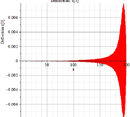
The plots in Figures 4 and 5 show that at a height of 5m the maximum deflection of the tower for this design is about 6.8mm at an angular speed of 19.5rad/s. This deflection is significant and hence not good operating speed for the system. But at a speed of about 18rad/s the deflection is about 2mm; this is a more suitable operating speed. The plot in Figure 6 is for a tower height of 7m. The maximum deflection of the tower is 4.7mm at a rotor speed of 11.5rad/s. but a lesser deflection of 1mm is obtainable at a speed of 10rad/s. The plot in Figure 7 is for a tower height of 10m. The maximum deflection at this height is 4mm at a speed of 6.5rad/s and a deflection of about 1mm at a speed of 5.5rad/s and 2mm for 11rad/s. The plots in Figure 8 is for a tower height of 12m. The maximum deflection of tower is 2.5mm at a rotor speed of 5rad/s and at a rotor speed of 4.5rad/s a deflection of 1mm.
Table 1: Maplesim components used
Component Use
A stationary frame with a fixed displacement and orientation relative to ground
Joint allowing one rotational degree of freedom about a given axis
A Rigid Body Frame is used to define locations of interest on the body where it is connected. The position and orientation relative to the center of mass must be defined for each body-fixed frame.
Center of mass (CoM) frame with associated mass and inertia matrix
Applies stiffness, damping, and actuation between two frames
ARampcomponent is used to apply a linearly
increasing angular speed to the rotor
This component generates a forced angular speed according to an input signal.
Figure 3: 3D View of Simulation
Figure 4: Angular frequency (rad/s) vs time (s)
Figure 5: Deflection(m) vs time(s) for tower height of 5m
Figure 6: Deflection (m) vs time(s) for tower height of 7m
Figure 7: Deflection (m) vs time(s) for tower height of 10m
Though tower heights of m and 7m offer a more stable system structurally at even high rotor speeds, from the design point of view of wind turbines, m and 7m heights are not sufficient for harvest of such energy [ ] except for situations where the towers will be mounted on other structures e.g. roof tops. Tower height of 2m on the other hand should have offered height advantage for energy capture but structurally wise for this design, it is the most unstable. We are therefore left with 0m as best option for structural stability and acceptable rotor speeds.
. CONCLUSION
In this study using Maplesim 20 . we have successfully modeled and simulated the tower vibration of horizontal axis wind turbine with unbalanced mass of rotor blades for different tower heights. We were able to determine acceptable rotor speeds for stability and also found out that the most suitable system for this case study is a turbine system that will offer a balance between energy capture and system stability. This information is important because it shows what range of speeds should be avoided from a structural point of view and whether structural modifications are required at the design stage. This also offers the opportunity to make several parameter changes to see how our structure will behave. Components that vibrate are a sign of malfunction and by simply looking at the displacement of the component the vibration can be measured. In wind turbine condition monitoring, vibration analysis is a common and effective way to be applied especially in the rotation parts. When the wind turbine is running, the system is under the non-stationary wind force. Therefore, it is necessary to analyze the vibration characteristic of the turbine structure, especially the rotor blades system.
. REFERENCES
[1] George, R. K. Transient Small Wind Turbine Tower Structural Analysis With Coupled Rotor Dynamic Interaction. MSc. Thesis, Faculty of California Polytechnic State University, San Luis Obispo, 2013.
[2] Paul, A. L. Onshore and Offshore Wind Energy: An Introduction. John Wiley & Sons, 2011.
[3] Caithness Windfarm Information Forum Wind Turbine Accident Data to December 31st 2005http://www.caithnesswindfarms.co.uk/ (accessed 30September 2007) 2005.
[4] lemming M L and Troels S. New lightning qualification test procedure for large wind turbine bladesInt. Conf. Lightning and Static Electricity (Blackpool, UK), pp 36.1– 10. 2003.
[5] Rosenbloom E. A. Problem with Wind Powerwww.aweo.org, 2006.
[6] Dolan D. S. L, “Real-time wind turbine emulator suitable for power quality and dynamic control studies”, MASc Thesis, Department of Electrical and Computer Engineering, University of Toronto, April 2005
[7] Dolan D. S. L. and Lehn P. W. “Real-time wind turbine emulator suitable for power quality and dynamic control studies”, International Conference on Power Systems Transients, IPST05, June 19-23 2005
[8] Cardenas, R Pena, RAsher, G. M and Clare, J. C. “Experimental emulation of wind turbines and flywheels for wind energy applications,” European Power Electronics and Applications Conference, EPE2001, Graz, Austria, August 2001
[9] Chang, L, Doraiswami, R, Boutot, T and Kojabadi, H. “Development of a wind turbine simulator for wind energy conversion systems,” Canadian Conference on Electrical and Computer Engineering, IEEE CCECE2000, Halifax, Canada, Vol. 1, pp. 550-554, 2000.
[10] Farret, F. A. Gules R. and Marian, J. “Micro-turbine simulator based on speed and torque of a DC motor to drive actually loaded generators, ”Proceedings of the 1995 First IEEE International Caracas Conference on Devices, Circuits and Systems, Vol. , pp. 89-93, December 1995.
[11] Battaiotto, P. E. Mantz R. J. and. Puleston, P. F “A wind turbine emulator based on a dual DSP processor system,”
Control Engineering Practice, vol. 4, pp. 1261-1266, 1996. [12] David Parker, “Computer based real-time simulator for renewable energy converters,” Proceedings of the First IEEE International Workshop on Electronic Design, Test and Applications, Vol. pp. 280-284, January 2002. [13] Matsumoto, Y. Umida H. and Ozaki, S. “Dynamic simulator
of the mechanical system,” International Conference on Industrial Electronics, Control and Instrumentation Proceedings. IECON ’9 , Vol. 1, pp. 527-532, October 1991.
[14] Inman, D. J. "Engineering Vibration", 3rd Edition. Upper Saddle River, NJ, 2008, Pearson Education, 2008.
[ ] MapleSoft Inc. Maplesim Response to Harmonic Excitation: Damped Systems [Online]. Available: http://www.maplesoft.com/content/EngineeringFunda mentals/8/MapleDocument_29/Harmonic%20Excitation %20Part%202.pdf. 2010.
[16] Distributed Wind Energy Association Tower Heights. DWEA Briefing Paper [online]. Available;