2D MINIPLATFORM FOR MEASURING FORCE AT A COMPUTER KEY BUTTON
Luiz Carlos Gertz, Milton Antônio Zaro, Jefferson Fagundes Loss
*
Lutheran University of Brazil – ULBRA, Canoas, Brazil
* Universidade Federal do Rio Grande do Sul, Porto Alegre, Brazil
Submitted in April, 2005
By the usage of computers, both at work and home, health problems due to typing started appear, mostly by the individual’s posture, upper limbs repetitive movements, forces, etc. Several studies for understanding the causes for these health problems have been carried out since the early 90’s. The main objective of this work is the development of a force platform to measure the finger’s applied force at the keyboard during computer typing. This platform will be used in Biomechanics and Motor Control applications. It was designed and built in order to measure vertical force Fz (z direction), horizontal force Fx (x direction) and transversal force Fy (y direction) and the moment applied in the horizontal (and longitudinal) axis Mx (x direction). Resistance strain gauges were used as sensors bonded in can-tilever beams. These sensors are connected to a Wheatstone full bridge, in order to measure, independently Fx, Fy and Mx. To developing the conception adopted, the force platform was evaluated and tested by a numerical model (finite elements technique). The data acquisition system is composed by (a) a computer, to acquire and further processing the collected information by (b) an A/D converter, (c) a signal conditioner and (d) the software SAD 2.0. The static calibration of the force platform presented linearity within the range of 3%. Dynamic tests showed that the platform has a fundamental frequency higher than 2300 Hz, and consequently permits its use for analysis of the applied forces during typing.
Keywords: Biomechanics, motor control, dynamometry, force platform, keyboard, typing.
INTRODUCTION
The first measurements of the force applied by fingers at a computer key button was carried out by Armstrong (1994) and Rempel (1994a). These authors developed two measuring systems: (a) one with two load cells connected to the lower part of the keyboard,
and (b) another one with a piezoelectricsensor under
the keycap. These two systems were used in several ex-periments to study the force applied to the computer keys. Some remarkable experiments were developed by Rempel (1994b, 1997, 1999), Serina (1997) and Smutz (1994). In all these studies, the systems were restricted to the measurement of force in a single axis (vertical). Today, force platforms (which measure forces and force moments at three axes) are being produced to analyze either human and animal body movements.
The objective of this work is to develop a force plat-form that measures the force applied by the fingers on the surface of a computer key button during typing. This platform measures the force in two axes: y (transversal to the keyboard) and z (vertical), and the moment in one axis, x (longitudinal to the keyboard). With this data it is possible, in a bidimensional analysis, to determine the magnitude of the resulting force vector applied on the key button, its angle in relation to the keyboard’s
transversal axis (y axis) and the position of the force vector at the key in relation to the x axis.
THEORETICAL FUNDAMENTS
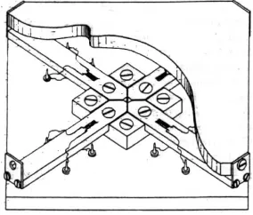
In 1964, Petersen built a force platform to work with small animals. It was composed by 4 cross-shaped
cantileverbeams, with edges fixed at the superior base
(contact surface), and its center fixed at the inferior base (Fig. 1). This equipment reads the same value of force regardless the surface region where the force is applied.
Fig. 1
In 1987, Lywood developed a force platform that measures force at three orthogonal axes. The structure is similar to that constructed and reported by Petersen’s (cross-shaped), in which it was measured the vertical force. However, two other sets of four beams were added in order to measure the two force components in hori-zontal position.
Based on Lywood’s project, Roesler used a similar structure and developed, in 1997 a platform that meas-ures forces and force moments in three axes. This plat-form is waterproof, in order to be used in researches related to activities carried out in swimming pools (hy-drogymnastics).
PROJECTING THE FORCE PLATFORM
The small dimensions involved in the making of this force platform and the limitations related to the size of the sensors (resistance strain gages) determined the un-feasibility of tridimentional analysis. The chosen option was a system which is capable of a bidimentional analy-sis at the transversal position (sagittal plane). There-fore, the measurement of one of the force components and one of the moments was disregarded. This analysis needs the force measurement at z, Fz direction, and at y, Fy direction and the x, Mx moment. By determining the force at z, Fz, and the force moment at x, Mx direction, it is possible to determine the force vector position in
relation of y axis, Dy, since Dy = M Fx
z and that Fy does
not cause force moment atx axis.
To measure these three components, it is necessary to have three independent Wheatstone bridge circuits, which means twelve sensors, a number considered too high to fit in the available space.
The force platform boards were built in two parts: (a) the upper part, with elastic elements (boards), where the sensors that measure force at z, Fz direction and moment at x, Mx direction would be placed, and (b) the lower part, composed by the elastic elements (boards) where the sensors that measure force at y, Fy direction would be placed.
The upper part is formed by a structure with a “H” shape. This format enabled a very interesting solution for measuring Fz and Mx. At a force platform used to study human gait, the sensors that measure force can be fixed at the same side of the sensors that measure the force moment; the beams are wide enough for that purpose. However, the width of the beams in this project is determined by the sensor’s width, which allows only one sensor to be fixed at each side of the platform.
The lower part is formed by four cantilever beams; the force is applied at the upper edges.
HOW THE FORCE PLATFORM WORKS
This force platform works similarly to a table where every leg is substituted by a spring. When a load is ap-plied to the center of the table, each spring suffers equal deflection; however, if the load is exentrical to the center of the table, a bigger strain will be induced at the nearest spring. Regardless the position in which the force is ap-plied, the average strain in the four “springs” (cantilever beams) will be the same.
The same principle should be applied to the “H” format structure in order to allow the measured force to be the same, regardless the point of application of this force at the surface of the key button. As the force plat-form circuit is mounted in a full bridge type, the bridge’s unbalance will be similar to the case where the force is applied at the center of the key. Therefore, if the applied force by the finger is displaced from the center of the key button, the reading of this component will not suffer any distortion, since the force platform was developed to compensate variations in positioning of the applied load. The same will happen with force moments.
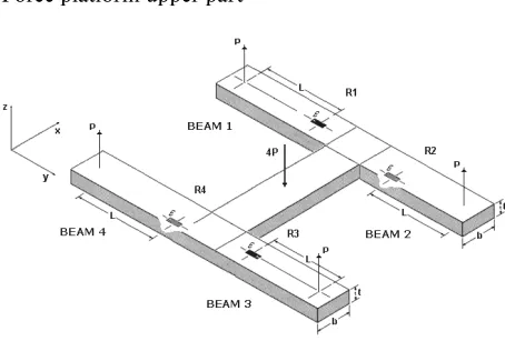
Fig. 2 shows a drawing that illustrates the force plat-form structure conceived to measure the force applied at z, Fz axis, and the force moment at x, Mx axis. This structure has two sensors attached at the upper part, on cantilever beams 1 and 3, plus other two at the lower part of beams 2 and 4.
Fig. 2
Force platform upper part
DIMENSIONING THE FORCE PLATFORM
beam can not be less than the sensor’s, that is, 2 mm, and length over 5 mm.
Thus, the upper part of the extensometric transduc-er is composed by 4 “H” – shaped cantilevtransduc-er beams, 2.0 mm wide, 6.0 mm long, 0.4 mm thick each, total length of 14 mm between the anchors at the lower part, and 15.0 mm wide. This geometry allows the sensors’ to be set like two complete Wheatstone bridges circuits, one to read the force at z, Fz axis, and the other to read force moment at x, Mx axis.
The lower part is also formed by four cantilever beams, which are 5.5 mm long, 2.0 mm wide and 0.2 mm thick, with four sensors connected in a full bridge type circuit, in order to read force at y, Fy direction.
To illustrate a typical responde of a H cantilever beam structure subjected to a force, Fig. 3 presents the strains calculated using the Finite Elements theory when forces are applied at three directions simultane-ously, one at x direction, Fx = 2N, another at y direction, Fy = 2N and the third at x direction, Fz = –3N.
Fig. 3
Force applied, Fx = 2N, Fy = 2N and Fz = –3 N; strain analysis using von Misse’s method
BUILDING THE FORCE PLATFORM
To produce the elastic elements, the force platform,
it was built on 304 stainless steel (210 × 109 N/m2).
Young modulus, 2.8 × 10⁸ N/m2 of tensile strength,
poison coefficient 0.28, density of 7.9 Kg/m3 (Sandivik,
1994). The choice was due to the high resistance to oxi-dation, mechanical high resistance and to be adequate for work with electroerosion process.
The extensometric sensors used at the force plat-form are Kyowa’s, KFG-1-120-C1-23N15C2 model, with a grid of 1 mm. It used the MB35 glue – (Micromeasure-ments) to fix the sensors at the beams’ surfaces.
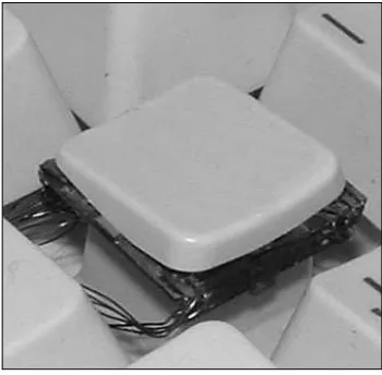
The base of a key button was prepared in order to fix sensorsat its inferior structure. The two sets with two serial cantilever beams were attached at the center of the base. The “H-shaped” upper structure was attached at the cantilever beams edges of the lower structure. The contact surface of the force platform was built using a computer key button, which was attached at the center of the “H-shaped” structure.
The connection between the upper and the lower structures should be roundso that it could only transmit force to the lower beams. However, it is not mechani-cally possible to produce such part with the required dimensions. Since the beams deformation is irrelevant, the option was to unite these parts with a small amount of glue, so that the stiffness of the union would be sig-nificantly less than the stiffness of the metal parts. Cy-anacrilate glue was used because it glues fast and it is apropriate to unite metals (Fig. 4).
Fig. 4
Platform lower view
CALIBRATING THE FORCE PLATFORM
Statistic calibration
In order to calibrate statically the force platform, a structure has been set to apply Fz, Fy and Mx loads independently in each of the directions. Therefore, when a load is applied in one direction, there can not be any other component in another direction (as suggested by Gola, 1980; Hall, 1996), avoiding “mechanical cou-pling”.
bridge circuit of the load cells is 4V or 10V. However, due to the beams’ tiny structure, the best option was to 2V, since the objective was to avoid overheating of the structure.
The calibration was made by applying force using dead weights. According to Gola (1980), if the dynamic analysis shows that the force platform is light and stiff enough, and if the vibration modes are sufficiently high compared to the vibration modes of the applied forces during measurement, the static calibration is valid.
Several data aquisition sets where conducted at one direction with the load applied in order to verify me-chanical coupling, repetitivity and linearity. The results presented are the mean of three values each of a series of different measurements.
SAD32 software was used for signal analysis; it was used the mathematical function called Mobile Weighted Mean, with a cut-off frequency of 0.45 Hz. The sampling rate chosen was 10 points per second.
When a force of 0.53 N was applied towards z axis, in several points of the load cell surface, the maximum error range was less than 4%. At the central position of the surface of the force platform the error range was less than 2%. Force readings towards y, Fy direction were almost zero. The system’s sensitivity at z axis, force Fz, was 0.0063 N, with R2 = 0.9998.
The force moment variation at x, Mx direction, caused by the applied force towards z, Fz, was zero.
To an 1N force applied towards z direction, the maxi-mum force registered at Fy was inferior than 0.001 N, a considerably low value if compared to the values regis-tered during typing, which almost reached 0.4 N. Taking this value as a reference, it can be stated that Fz force generates mechanical coupling at Fy of 0.25% from the maximum value registered when typing at normal speed.
The calibration curve of the applied force to-wards y, Fy direction, displayed a correlation coeffi-cient R2 = 0.994. The calibration curve at the moment at x, Mx direction, displayed a correlation coefficient R2 = 0.9991.
When a moment is applied towards x, Mx direc-tion, not exceeding 0.0070 Nm, which is approximately the maximum value mean registered during typing, the highest value registered by force at z, Fz direction, is 0.032 N. Considering that the force at z, Fz direction, reached maximum values close to 1.6 N during typing, it is appropriate to say that the mechanical coupling that Mx causes at Fy is less than 2%.
Concerning to the force at y, Fy direction, the high-est value found was 0.0022N. Considering that Fy regis-ters maximum values close to 0.4 N, it can be assumed that the mechanical coupling caused by Mx at Fy force component measurements during typing is less than 5.5%.
Dynamic calibration
For the dynamic calibration, it was used a Thüringer Industriewerk Bauestein vibratory table set. 5000/300, a 2250AMI-10 Endveco piezoceramic accelerometer (0.3 grams’ mass), Brüel & Kjaer cables, a 2034 dual channel signal analyzer Brüel & Kjaer, 9.93 mV/g sen-sitivity and a 102 Endveco signal amplifier and condi-tioner.
The accelerometer was fixed at the surface of the force platform, which was attached at the vibrating table. The range of vibration chosen was from 0 to 6.4 kHz, with the accelerometer also fixed at the vibrating table, and the output signals were sent to the signal analyzer.
The dynamic calibration showed that the first fun-damental mode of the force platform is superior to 2300 Hz. This result allows the equipment to be used safely in order to analyze events where the frequency does not exceed 750 Hz.
MEASUREMENTS
The desks used for typing can be adjusted to the keyboard’s height, in order to achieve a comfortably position according to the anthropometric characteris-tics of each typist. However, these tables are not rigid enough for simulations. For that matter, a 0.70 m high masonry table has been specially made for mechani-cal measuments, where the keyboard with the force platform (H-shaped) has been placed. Fig. 5 shows the force components in three different time moments dur-ing typdur-ing.
Fig. 5
Force components on key button’s surface
Fz ▲ Fy ! Mx
0 20 40 60 80 100 120 140
-3 -2 -1 0 1 2 3 -0.012 -0.008 -0.004 0.000 0.004 0.008 0.012 Fy Fx Force Moment ) m N( t n e m o M e cr o F ) N( e cr o F Time (ms)
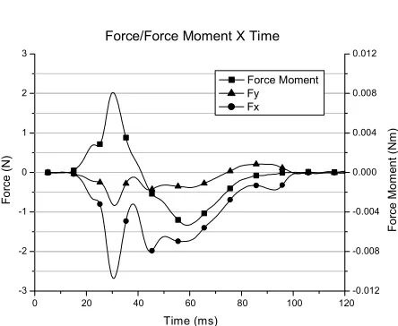
A representative model of the force components refering to three different moments during key button fingering can be seen in Fig. 6. It can be noticed that the pressure center on the surface of the force platform is initially placed at the furthest half from the typist’s body. However, when the key button reaches its course end, the pressure center changes position, moving over the surface to the nearest half from the typist’s body.
Maybe this fact can be explained because: (a) first, the finger movement on the surface of the key button and (b) second, because the pressure center of the fin-gertip’s contact area changes position as the applied force increases.
Initially, the pressure center is at the center of the finger’s contact area on the surface, when only skin tissues are being pressed; however, when the applied force increases, the pressure center moves to the edge of the finger, due to fingertip bone load (distal phalanx tuberosity).
Fig. 6
Force components on key button’s surface
Fz ▲ Fy ! Mx
0 20 40 60 80 100 120 -3 -2 -1 0 1 2 3 -0.012 -0.008 -0.004 0.000 0.004 0.008 0.012 Fy Fx ) N( e cr o F Time (ms) Force Moment Force/Force Moment X Time
) m N( t n e m o M e cr o F
Analyzing the results, one can assume that the force platform developed for this experiment displays accurate characterization of the applied force on the surface of computer key buttons.
In 1994, at the presentation of his innovative load cell, Rempel (a) stated that, at that point, there was not solid information on load force during typing, so it was useful to develop mathematical models with experimen-tal data to be used in the analysis of upper limbs (hands and fingers), as it has been proposed by Chao (1976).
Later, more complex models were created by Leijnse (1995, 1996 and 1997) and Biggs (1999). The informa-tion generated by the load cell developed in this work is more adequate to supply these models with experimen-tal data. Also, moving the key button to a 90 angle, it is
possible to measure force at the keyboard’s longitudinal axis.
CONCLUSIONS
The force platform produced in this work displayed enough sensitivity, sampling rate, repetition, mechani-cal uncoupling and precision, in order to measure two force components (and one force moment) of the ap-plied force at the surface of a key button during typing with great accuracy.
The force at y, Fy direction, denotes significantly representative level. By determining that, it is possible to observe important aspects concerning the key but-ton triggering characteristics from a typist. This force must not be taken for granted, as well as x, Fx direction force.
It has not been found any better equipment to de-scribe the characteristics of the applied force at a key button than the one presented in this work.
REFERENCES
Amstrong, T., Foulke, J. F., Martin, B. J., Gerson, J., & Rempel, D. ( 1994). Investigation of applied forces
in alphanumeric keyboard work. Am. Ind. Hyg. Assoc.
Journal, 55(1), 30–35.
Chao, E. Y., Opgrande, J. D., & Axmear, F. E. (1976). Three-dimensional force analysis of finger joints in selected isometric hand functions. Journal of Biome-chanics, 9, 387–396.
Garcia, H. T., Carvalho, A. A., Faria, U. C., & Silva, J. G. (2000). Avaliação do desempenho de sensores tácteis com elementos poliméricos resistivos. Congresso Bra-sileiro de Engenharia Biomédica, 620–625.
Gertz, L. C. (1997). Desenvolvimento de sistema para
análise biomecânica da tarefa de digitação. Thesis, Universidade Federal do Rio Grande do Sul, Escola de Engenharia, Porto Alegre.
Gola, M. M. (1980). Mechanical design, constructional details and calibration of a new force plate. Journal of Biomechanics, 13, 113–128.
Hall, M. G., Fleming, H. E., Dolan, M. J., Millbank, S. F. D., & Paul, J. P. (1996). Static in situ calibration of force plates. Journal of Biomechanics, 29(5), 659–665. Kyowa (1998). Strain Gauges, a complete lineup of high
performance strain gauges and accessories. Cat. no. 102b-U1. São Paulo: Kyowa.
Leijnse, J. N. A. L. (1996). A graphic analysis of the biomechanics of the massless bi-articular chain: Application to the proximal bi-articular chain of
the human finger. Journal of Biomechanics, 29(3),
Leijnse, J. N. A. L., & Kalker, J. J. (1995). A two-di-mensional kinematic model of the lumbrical in
the human finger. Journal of Biomechanics, 28(3),
237–249.
Leinjse, J. N. A. L. (1997). Why the lumbrical muscle should not be bigger: A force model of the lumbrical
in the unloaded human finger. Journal of
Biomechan-ics, 30(11–12), 1107–1114.
Lywood, D. W., Eyken, A., & Mcpherson, J. M. (1987). Small, triaxial force plate. Medical & Biological Engi-neering & Computing, 25, 698–701.
Petersen, W. A., Brookhart, J. M., & Stone, S. A. (1964). A strain-gage platform for force measurements. Jour-nal of Applied Physiology, 20(5), 1095–1097.
Popov, E. P. (1978). Introdução à mecânica dos sólidos.
São Paulo: Edgar Blücher.
Rempel, D., Dennerlein, J., Mote Jr., C. D., & Arm-strong, T. (1994). A method of measuring fingertip
loading during keyboard use. Journal of
Biomechan-ics, 27(8), 1101–1104.
Rempel, D., Klinemberg, E., Serina, E., Martin, B., Arm-strong, T., Foulke, J., & Natarajan, S. (1994). Finger force during computer keyboard work: Part II – Rela-tion of keyboard reacRela-tion force to finger flexor mus-cles surface EMG. Occupational Health & Safety, 2, 210–203.
Rempel, D., Serina, E., Klinemberg, E., Martin, B. J., Armstrong, T. J., Fooulke, J. A., & Natarajan, S. (1997). The effect of keyboard keyswitch make force on applied force and finger flexor muscle activity.
Ergonomics, 40(8), 800–808.
Rempel, D., Tittiranonda, P., Buraster, S., Hudes, M., & So, Y. (1999). The effect of keyboard keyswitch
design on hand pain. JOEM, 41(2), 111–119.
Roesler, H. (1997). Desenvolvimento de plataforma de
força subáquatica para medições de forças e momen-tos nos três eixos coordenados para utilização em biomecânica. Thesis, Universidade Federal do Rio Grande do Sul, Escola de Engenharia, Porto Ale-gre.
Serina, E. E., Mote, C. D., & Rempel, D. (1997). Force response of the fingertip pulp to repeated com-pression-effects of loading rate, loading angle and
anthropometry. Journal of Biomechanics, 308(10),
1035–1040.
Serina, E. R., Mockensturm, E., Mote Jr., C. D., & Rem-pel, D. (1998). A structural model of the forced
com-pression of the fingertip pulp. Journal of Biomechan-ics, 31, 639– 646.
Smutz, P., Serina, E., & Rempel, D. (1994). A system for evaluating the effect of keyboards design on force,
posture, comfort, and productivity. Ergonomics,
37(10), 1649–1660.
Spoor, C. W. (1983). Balancing a force in the fingertip of a two-dimensional model without intrinsic mus-cles. Journal of Biomechanics, 16(7), 497–504. Weightman, B., & Amis, A. A. (1982). Finger joint force
predictions related to design of joint replacements.
Journal of Biomedicines, 4, 197–205.
2D MINIPLATFORMA PRO MĚŘENÍ SÍLY VYVÍJENÉ NA KLÁVESNICI POČÍTAČE
(Souhrn anglického textu)
V souvislosti s používáním počítačů v zaměstnání i doma se začínají objevovat zdravotní problémy souvise-jící se psaním na počítači, způsobené většinou držením těla jednotlivce, opakovanými pohyby horních končetin, jimi vyvíjenou silou atd. Od začátku 90. let 20. století již bylo provedeno několik studií s cílem pochopit příčiny těchto zdravotních problémů. Hlavním cílem této práce je vytvoření silové platformy pro měření síly vyvíjené prs-tem na klávesnici při psaní na počítači. Tato platforma bude využívána v aplikacích biomechaniky a motorické kontroly. Byla vyvinuta a vyrobena za účelem měření vertikální síly Fz (směr z), horizontální síly Fx (směr x), transversální síly Fy (směr y) a momentu aplikované-ho v aplikované-horizontální (a podélné) ose Mx (směr x). Jako senzory byly použity odporové tenzometry umístěné na konzolovém nosníku. Tyto senzory jsou za účelem ne-závislého měření Fx, Fy a Mx připojeny na plný Wheat-stonův můstek. Pro účely rozvoje byla silová platforma vyhodnocována a testována pomocí numerického mode-lu (metodou konečných prvků). Systém získávání dat se skládá z (a) počítače pro sběr a další zpracování infor-mací získaných pomocí (b) měniče proudu, (c) zařízení upravujícího signál a (d) softwaru SAD 2.0. Statická ka-librace silové platformy vykazovala lineárnost v rozmezí 3 %. Dynamické zkoušky prokázaly, že platforma má základní frekvenci vyšší než 2300 Hz a že tudíž může být použita pro analýzu sil vyvinutých při psaní.
Luiz Carlos Gertz, Ph.D.
Education and previous work experiencePh.D. in Engineering and an associate professor of the Mechanical Engineering graduate course at ULBRA, where he works since 2002. He is responsible for the Data Handling (in the Masters course) and Ergonom-ics (in the lato sensu postgraduate course) disciplines. He is a council member of the Mechanical Engineering graduate course and a member of the Brazilian Society of Biomechanics.
Scientific orientation
Mechanics for Engineers disciplines, Internal Combus-tion Engines, EvoluCombus-tion of Automobile and Mechani-cal Automotive Systems (brake, suspension and direct systems).