Amirkabir University of Technology (Tehran Polytechnic)
Vol. 45, No. 2, Fall 2013, pp. 11-18
Amirkabir International Journal of Science& Research (Electrical & Electronics Engineering)
AIJ-EEE) )
*
Corresponding Author, Email: [email protected]
Suggested New Voltage and Frequency Control
Framework for Autonomous Operation of Microgrids
B.Poornazaryan
1, M. Abedi
2*, G. B. Gharehpetian
2and S. Shokoohi
31- MSc. Student, Department of Electrical Engineering, AmirkabirUniversity of Technology, Tehran, Iran 2- Professor, Department of Electrical Engineering, Amirkabir University of Technology, Tehran, Iran
3- Instructor, Iranian Oil Pipelines and Telecommunication Company (IOPTC), Sananadaj, Iran
ABSTRACT
Decentralized control strategies are popular candidates in microgrids control because of their reliability
and performance. Conventionally, droop control (as a main decentralized strategy) is been utilized in order to
prevent permanent droop of voltage and frequency after change in loads and also to share generated power
between distributed generation units. In this paper, a new droop control strategy was introduced to control
the voltage and frequency of autonomous microgrids. Following a review of the basic droop equations, it
was concluded that the new form of droop equations enhanced the voltage and frequency control
performance better than conventional droop equations. The voltage control behavior in the proposed method
was within the acceptable range, and the frequency also returned to the nominal value after a change in
loads. The simplicity and accurateness of the proposed method is a unique characteristic compared with the
other recent control methods. Simulation studies showed the effectiveness of the proposed control strategy in
different scenarios.
KEYWORDS
1-INTRODUCTION
The main advantage of microgrids is their ability to utilize microsources to both generate electricity and enhance its reliability; motivations for microgrid development includes the ancillary services of microgrids such as power reserve capability, supplying far or out-of-the-way loads, and voltage and frequency regulation by injection of reactive and active powers [1]. Microgrid development needs several prerequisites such as new control strategies for power electronic converters, protection designs, power management plans [2]. Control of the power electronic interfaces is associated with the microgrid mode of operation; in grid connected mode the controllers focus on producing specified active and reactive powers (namely, PQ mode); and in islanded mode, because of absence of voltage and frequency references, one or several units should be controlled in order to generate the frequency and voltage references (namely, v/f mode of operation) [3]. In autonomous or islanded microgrids , any inverter interfaced DG (IIDG) should control its local voltage and frequency in the absence of a communication link in order to have good reliability and supplying more loads [4]. The control of IIDG is based on conventional droop control as an imitation of synchronous generators behavior [5]. Because of the inaccurateness of the conventional droop control, new control strategies are being introduced, step by step, to minimize its shortcomings [6-8]. In [9], a novel method is proposed to control the parallel inverters either in islanded or grid connected mode has been proposed. This method mitigates the harmonics and takes the R/X ratio of interface impedance into account. In [10], a new angle droop controller is compared to a conventional droop controller and it is concluded that angle controller shares the power with lower frequency deviation. In [11], a decentralized control method is proposed in order to control the ac single phase microgrids. The proposed method combines droop control with a derivative controller in islanded mode; in addition, a small signal analysis has been presente.
The parallel voltage source inverters (VSIs) can be hierarchically controlled, the primary control may include droop control and virtual impedances, the secondary control restores the voltage and frequency, and the tertiary control regulates the power flow between microgrid and upstream network [12]. In [13], a new droop control method has been introduced in order to better reactive power sharing; this method utilizes from time derivative of voltage and includes a mechanism to restore it. In [14], design of a droop control in d-q frame for island microgrids is implemented and an virtual impedance has been designed to ensure stable operation of an experimental microgrid. Novel droop control structure review is introduced in [15].
The microgrid can be controlled through a two layer control framework, the first layer controls the voltage and
frequency of the microgrid by voltage controlled VSIs (VCVSI) and the second layer adjusts the active and reactive powers by current controlled VSIs (CCVSI) [16]. The virtual flux droop method has been introduced in [17] in a way that, the power sharing is realized through adjusting the phase angle and drooping the flux amplitude. Irrespective of the kind of droop control, the small signal stability of the microgrid should be analyzed thoroughly [18] and state space equations of the microgrid can be profitable [19]. A comprehensive study on the droop coefficients can be found [20]. A novel strategy that minimizes the circulating current and current sharing difference between the converters can be seen in [21].
In this paper, the droop equations introduced in [15] are rewritten in a sensible form for all microgrids (resistive or inductive) called novel droop control (NDC). Some insensible assumptions have been considered in constructing the droop equations in [15] that aren‟t available in the NDC equations; For instance, the parameter Kv considered to be fixed at unit in this reference. The driven droop equations are clear enough for easy implementation. After implementing these equations in VSI control structures, the notable results showed the microgrid‟s frequency and voltage can be controlled effectively. In this method, the need for secondary frequency control will be removed and the voltages deviations are small.
2-NOVEL DROOP CONTROL (NDC)
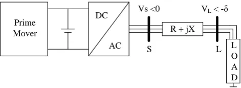
In order to derive the droop equations, a simple microgrid consists of a VSI, a line and a load is depicted in Fig. 1.
Prime Mover
DC
AC
R + jX
L O A D S
Vs <0 VL < -δ
L
Fig. 1. Simple microgrid supplying a load via an IIDG The active and reactive powers flow from the IIDG into the load can be formulated as follows [15]:
(1)
2 2 (V V cos ) XV sin
s
s L L
V
P R
R X
(2)
2 2 V sin X(V V cos )
s
L s L
V
Q R
R X
(3)
. . s
s P P P V V (4)
. . s
s Q Q Q V V
Assuming that the operation point is around A = (δ0, Vs0) and it has small deviations, so using the forgoing
equations it can be linearized as
0 0
0 0
2 2 ( , )
2 2 ( , )
. .sin . .cos .
1
(2 .cos ) . .sin ..
S
S s
L L V
s L L V s
V
P R V X V
R X
R V V X V V
R X (5) 0 0 0 0
2 2 ( , )
2 2 ( , )
. .cos . .sin .
1
. .sin (2 .cos ) .. S
S s
L L V
L S L V S
V
Q R V X V
R X
R V X V V V
R X (6)
These equations are the milestones of the NDC relationships. It is assumed that the operating point is located around the (0, VL), so the equations 5 and 6 can be abbreviated here:
(7)
2 2 2 2
1
. .
S
L L S
V
P X V R V V
R X R X
(8)
2 2 2 2
1
. .
S
L L S
V
Q R V X V V
R X R X
After some simplification ones reaches these relationships: (9)
1 . . 2f X P R Q
(10)
. .
S
V R P X Q
Using the equations 16 and 17, two control relationships have been introduced, these relationships are called the novel droop control relationships (NDC):
(11) 0 P.
f f m f
(12)
0 .
S S Q S
V V n V
Hereinafter, the equations 11 and 12 were used in control of the VSI in microgrid. These relationships are similar to the conventional droop equations, but, these relations consider the mutual correlation between the frequency deviation and the voltage deviation. So, it was expected that these new droop equations would better control the voltage and frequency in all types of microgrids.
3-MICROGRID VOLTAGE AND FREQUENCY CONTROL
In a situation similar to the conventional power system with several generators, it becomes important to control the voltage and frequency when several DGs supply the microgrid [5]. VSIs in the microgrid act as an interface between the prime mover and the output power.
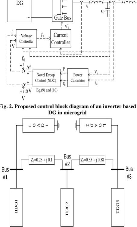
In order to verify the performance of the NDC, it was implemented on the VSIs, as shown in Fig.2. This figure shows the schematic diagram of the proposed control diagram for an inverter based DG in a microgrid using the NDC relationships. Some comments that clarify the control methodology are presented below.
3-1- POWER CALCULATOR
First, the instantaneous active and reactive powers are calculated by the d-q axis components of the measured voltage and current:
(13) ( d. d q. q)
pV I V I
(14) ( d. q q. d)
qV I V I
To smooth instantaneous powers, these power components are passed through low pass filters as follows:
(15)
( c ).p
c P s (16)
( c ).
c Q q s
Where, ωc is the cut-off frequency of the filter. Generally, a microsourse generates active and reactive powers near its nominal values. Hereinafter, using the control diagram (see Fig.2) and the power relationships in Eq (15) and (16), the NDC block can be supplied, subsequently. It has been suggested that the nominal values of power for an individual DG can be selected as the reference values of powers. The NDC block generated the deviation values (Δf and ΔV) and these values were added to their reference values, respectively. The outcomes of the previous process were fed into the pulse width modulation (PWM) generator in order to build the desirable voltage in its output.
It was clear that, similar to all droop-based control methods, the proposed method had also a local nature, so the need for any communication links was eliminated. One major issue was to select the droop coefficients for a given inverter; in an allowable range of frequency control. It is suggested that these values can be estimated by these relationships:
(17) max min max p m P (18) max min max od od q V V n Q
3-2- VOLTAGE CONTROLLER
The voltage control block seen in Fig.2, includes the feed-forward and feedback loops; necessary in order to generate the current commands in the d-q frame. The operation of this block can be explained by two equations (as illustrated in Eqs.19 and 20) [18]:
(19) K
( )( )
s
iv
ld od f oq pv od od
i Fi C v K v v
(20) ( iv)(v )
lq oq f od pv oq oq
K
i Fi C v K v
s
In the previous equations, ω is the angular frequency of the system and parameter “F” is the feed-forward coefficient assigned in order to have low output impedance and to enhance the performance rejection. The Kpv and Kiv are the PI controller coefficients adjusted by classical pole-zero and bode techniques.
3-3- CURRENT CONTROLLER
The current controller generates the voltage commands in order to feed the PWM generator. The operation of this unit can be summarized by two equations in the d-q frame:
(21) ( ic)( )
id f lq pc ld ld
K
v L i K i i
s
(22) ( ic)( )
iq f ld pc lq lq
K
v L i K i i
s
It is suggested that, the current controller is designed to have a bandwidth of about 1.6- kHz [18].
3-4- OUTPUT LC FILTER
In [18] , the main criteria of designing the LC filter is to attenuate the ripple of the output voltage by the factor of 100; consequently, by a rule of thumb, the resonant frequency of the LC filter should be 10× less than the frequency of switching. Hereinafter; based on the test system introduced in [18], the simulation studies were conducted. The full data of the controllers and test system are commutated in a data table in order to use them in the system implementation.
4- SIMULATION AND RESULTS
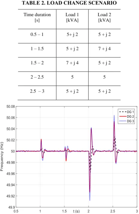
The proposed methodology has been implemented and examined on a 3-bus test microgrid that consists of three DG units (Fig.3). The full details of this microgrid can be found in [15]. It should be mentioned that; irrespective of the size or complexity of the microgrid, the proposed method was operated accurately. In the other words, the focus of this study was on the control method not on the microgrid topology; the desired microgrid was implemented in the Matlab/Simulink environment. A severe load change scenario was (as given in Table I) imposed on the microgrid. In order to have a deep analyzes, these scenarios included capacitive, inductive and resistive loads switching. The line impedance for all DGs was equal, R=0.5 and X=0.5.
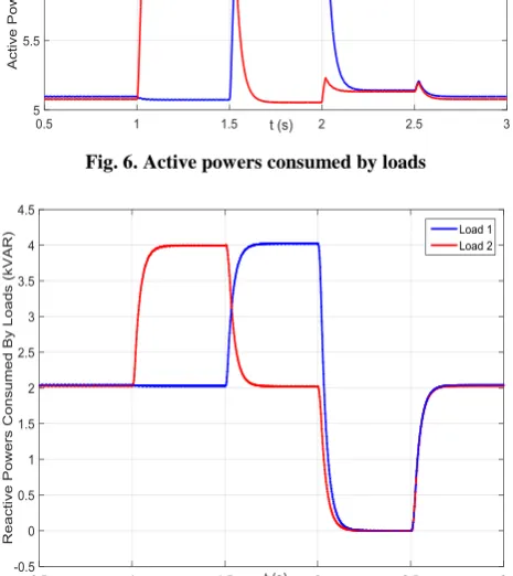
4-1-THEFREQUENCYDEVIATIONUNDER LOADCHANGESCENARIOS
Figure.4 show the frequency of all IIDGs has been effectively controlled and the frequency deviations in the load change points are acceptable. As it is obvious, the proposed frequency control effectively returned the frequency to its nominal value.
According to Fig.4, the frequency deviation in t=1.5s was larger than the other switching times. This was due to the active power variations and the reactive power variations having inverse signs at this point according to Table I; consequently, according to Eq.(10) , the frequency deviation had the largest value. Using a similar idea logic, one can understand why the frequency deviation at t = 2s was larger than the other points. One prominent observation is that the frequency deviation for DG 2 was the smallest one, because this unit was subjected to smaller power variations and did not have any local load in its terminal. In this figure, the black hatched line has the smallest amplitude among all three DGs. Voltage Controller Current Controller Power Calculator Novel Droop Control (NDC) Lc Lf Cf Vi V* i il
Vo i o
Vo
io
Q i*l
P Vt PWM Inverter Gate Bus DG f0 Δf ΔV f V V
Eq.(9) and (10)
Fig. 2. Proposed control block diagram of an inverter based DG in microgrid
I I D G 1 I I D G 2 I I D G 3
Z2=0.35 + j 0.58 Z1=0.23 + j 0.1
L O A D 1 2 D A O L
Bus #1 Bus #2 Bus #3
TABLE 1. TEST SYSTEM AND CONTROLLERS PARAMETERS
TABLE 2. LOAD CHANGE SCENARIO
Time duration [s]
Load 1 [kVA]
Load 2 [kVA]
0.5 – 1 5+ j 2 5 + j 2
1 – 1.5 5 + j 2 7 + j 4
1.5 – 2 7 + j 4 5 + j 2
2 – 2.5 5 5
2.5 – 3 5 + j 2 5 + j 2
Fig. 4. Frequency profile of IIDGs during load change scenario
4-2-THE RMS VOLTAGES OF IIDGs UNDER
LOAD CHANGE SCENARIOS
The RMS values of voltage for all IIDGs have been depicted in Fig.5. The proposed control method includes only the primary voltage control; so, the voltage drop and jump were expected. As shown in Fig.5, the voltage drops in the critical load change scenario were small and acceptable. The undesired overshoots at the points of switching (such as t = 1.5s) are the results of severe load changes (both active and reactive powers). For example, in t = 1.5s, the overshoot in Fig.5 was maximum because the active power variation and the reactive power variation for each load have the same signs (positive or negative). So, according to Eq. (10), the values of active power and reactive variations are summed and therefore, large overshoots are seen in this instant. It should be noted that, DG 2 had the largest RMS value of voltage in all intervals because the other DGs picked up more currents from their local loads; therefore, the smallest power sharing was reached at DG 2. But in a different scenario, a close competition between DG 2 and DG 3 was followed in order to have the biggest RMS value of voltage.
Fig. 5. RMS voltage profile of IIDGs during load change scenario
4-3-THE CONSUMED ACTIVE AND
REACTIVE POWERS
In order to better understand the patterns of Figs 4 and 5, the load powers are illustrated in Figs 6 and 7. These figures correspond with the data available in Table I; for example, the active power consumed by DG1 was 5 kW in all intervals except in the third half of the seconds where the active power of DG 1 jumped from 5 kW to 7 kW. From Figs 6 and 7 it is obvious that proposed controller can follow the power commands both quickly and accurately. It should be mentioned that the small deviations in the active power curve were resulted from the resistance of the breakers that switch the loads. For example, in t = 2s in Fig.6, the small deviation in the active power curve amplitude is the result of the breakers resistances.
Parameter Value Parameter Value
Inverter Rating 10 kVA Rated Voltage 380 V
fs 10 kHz mp 9.4 × 10⁻⁵
Lf 1.35 mH nq 1.31 × 10⁻³
Cf 50 μF Kpv 0.05
rf 0.01 Kiv 390
LC 0.35 mH Kpc 10.5
rLc 0.01 Kic 16 × 103
ωc 31.41 F 0.8
4-4-THE GENERATED ACTIVE AND REACTIVE POWERS OF DGs
The load change scenario may lead to the power sharing between IIDGs and undoubtedly, the closer to the load location, the larger the power of the IIDG. This can be seen in the second half interval (1< t <1.5) where the share of IIDG 3 from the active power of the load was maximum because its location was the nearest location; and the share of IIDG 1 in this scenario was the smallest one. As mentioned earlier, the active power and reactive power variations (their value and the sign of them) play the determinant roles in the transient and steady state response of the frequency and the voltage curve in the load change instants. As it can be seen in Fig.6 to Fig.9, in the microgrid unlike conventional power systems, voltage variation is mostly related to both active and reactive powers. As expected, the power responses of inverter based DGs were fast enough unlike the responses of the machine-based DGs (i.e., Diesel generator).
The droop coefficients have the determinant roles in assigning the share of any DG unit from the load, and power sharing methods should be utilized in order to better share power between DG units in the microgrid.
Fig. 6. Active powers consumed by loads
Fig. 7. The reactive powers consumed by loads
Fig. 8. The active powers generated by DGs
Fig. 9. The reactive powers generated by DGs 5- CONCLUSIONS
In this paper, following a brief review of the conventional droop control method for multiple inverters in microgrids, a new form of droop equations was deduced and introduced in order to replace the conventional droop equations. These new equations; called NDC, were then utilized in the control block diagram of IIDG‟s in the microgrid. The simulation studies were performed in order to analyze the effectiveness of the proposed NDC controller in the microgrid. In order to keep the generality of the problem, interface impedances with equal resistance and reactance have been used for all IIDG units.
and consequently, it didn‟t need any communication link between DGs; this is a suitable characteristic for all droop based methods in the microgrid.
ACKNOWLEDGMENT
The authors would like to thank Peyman Karimyan from the Electrical Engineering Department, Amirkabir University of Technology (Tehran Polytechnic) for his valuable suggestions and comments to improve the quality of this manuscript.
REFERENCES
[1] S. Chowdhury, S.P. Chowdhury, P. Crossley,“Microgrids and active distribution networks”, IET Renewable Energy Series 6, 2009.
[2] Hartono, B.S., Budiyanto, Y., Setiabudy, R., “Review of microgrid technology,” QiR (Quality in Research), 2013 International Conference on , vol., No., pp.127,132, 25-28 June 2013.
[3] Juan Carlos V´asquez Quintero, “Decentralized control techniques applied to electric power distributed generation in microgrids”, a dissertion accepted for the degree of European Doctor of Philosophy, June 2009.
[4] Chen Hongbing, Zhang Xing, Liu Shengyong, Yang Shuying, “Research on control strategies for distributed inverters in low voltage micro-grids,” Power Electronics for Distributed Generation Systems (PEDG), 2010 2nd IEEE International Symposium on , vol., No., pp.748,752, 16-18 June 2010.
[5] P. Kundur, “Power system stability and control”, McGraw-Hill Inc., New York,1994.
[6] Baudoin, S., Vechiu, I., Camblong, H.,”A review of vtage and frequency control strategies for islanded microgrid,” System Theory, Control and Computing (ICSTCC), 2012 16th International Conference on , vol., No., pp.1,5, 12-14 Oct. 2012.
[7] Koda, E., Bando, S., Asano, H., “Evaluation of smoothing effects of autonomous control of microgrids on line flow fluctuations at the coupling point with the utility grid,” Energy Conversion Congress and Exposition, 2009. ECCE 2009. IEEE , v., no., pp.535,540, 20-24 Sept. 2009.
[8] Pecas Lopes, J.A., Moreira, C.L., Madureira, A.G., “Defining control strategies for MicroGrids islanded operation,” Power Systems, IEEE Transactions on , vol.21, No.2, pp.916,924, May 2006.
[9] De Brabandere, K., Bolsens, B., Van den Keybus, J., Woyte, A., Driesen, J., Belmans, R.,
Leuven, K.U., “A voltage and frequency droop control method for parallel inverters,” Power Electronics Specialists Conference, 2004. PESC 04. 2004 IEEE 35th Annual , vol.4, No., pp.2501,2507,v.4, 2004.
[10] Majumder, R., Ghosh, A., Ledwich, G., Zare, F., “Operation and control of hybrid microgrid with angle droop controller,” TENCON 2010 - 2010 IEEE Region 10 Conference , vol., No., pp.509,515, 21-24 Nov. 2010.
[11] Jaehong Kim, Guerrero, J.M., Rodriguez, P., Teodorescu, R., Kwanghee Nam, „Mode adaptive droop control with virtual output impedances for an inverter-based flexible AC microgrid,” Power Electronics, IEEE Transactions on , vol.26, No.3, pp.689,701, March 2011.
[12] Vasquez, J.C.; Guerrero, J.M.; Savaghebi, M.; Eloy-Garcia, J.; Teodorescu, R., "Modeling, analysis, and design of stationary reference-frame droop-controlled parallel three-phase voltage source inverters," in Industrial Electronics, IEEE Trans. , vol.60, No.4, pp.1271-1280, April 2013.
[13] Chia-Tse Lee, Chia-Chi Chu, Po-Tai Cheng, “A new droop control method for the autonomous operation of distributed energy resource interface converters,” Energy Conversion Congress and Exposition (ECCE), 2010 IEEE , vol., No., pp.702,709, 12-16 Sept. 2010.
[14] Planas, E., Gil-de-Muro, A., Andreu, J., Kortabarria, I., Mart nez de Alegr a, I., “Design and implementation of a droop control in d-q frame for islanded microgrids,” Renewable Power Generation, IET , vol.7, No.5, pp.458,474, Sept. 2013.
[15] Bevrani, H., Shokoohi, S., “An Intelligent Droop Control for Simultaneous Voltage and Frequency Regulation in Islanded Microgrids,” Smart Grid, IEEE Transactions on , vol.4, No.3, pp.1505,1513, Sept. 2013.
[16] Bidram, A., Davoudi, A., Lewis, F.L., “A multiobjective distributed control framework for islanded AC microgrids,” Industrial Informatics, IEEE Transactions on , v.10, no.3, pp.1785,1798, Aug. 2014.
[17] Jiefeng Hu, Jianguo Zhu, Yanqing Qu, Guerrero, J.M., “A new virtual-flux-vector based droop control strategy for parallel connected inverters in microgrids” ECCE Asia Downunder (ECCE Asia), 2013 IEEE , vol., no., pp.585,590, 3-6 June 2013.
pp.613,625, March 2007.
[19] Xuan Zhang, Jinjun Liu, Zhiyuan You, “A state space model of paralleled inverters based on droop control in grid-connected microgrid,” Applied Power Electronics Conference and Exposition (APEC), 2014 Twenty-Ninth Annual IEEE , v., no., pp.1815,1820, 16-20 March 2014.
[20] Hernandez-Aramburo, C.A., Green, T.C., Mugniot, N., “Fuel consumption minimization of a microgrid,” Industry Applications, IEEE Transactions on , v.41, no.3, pp.673,681, May-June 2005.
[21] Augustine, S., Mishra, M.K.,