www.geosci-instrum-method-data-syst.net/4/149/2015/ doi:10.5194/gi-4-149-2015
© Author(s) 2015. CC Attribution 3.0 License.
Improving of electrical channels for magnetotelluric
sounding instrumentation
A. M. Prystai and V. O. Pronenko
Lviv Centre of Institute for Space Research, Lviv, Ukraine
Correspondence to: V. O. Pronenko (pron@isr.lviv.ua)
Received: 26 January 2015 – Published in Geosci. Instrum. Method. Data Syst. Discuss.: 2 April 2015 Revised: 2 July 2015 – Accepted: 16 July 2015 – Published: 30 July 2015
Abstract. The study of the deep structure of the Earth’s crust is of great interest for both applied (e.g. mineral exploration) and scientific research. For this the electromagnetic (EM) studies which enable one to construct the distribution of elec-trical conductivity in the Earth’s crust are of great use. The most common method of EM exploration is magnetotelluric sounding (MT). This passive method of research uses a wide range of natural geomagnetic variations as a powerful source of electromagnetic induction in the Earth, producing telluric current variations there. It includes the measurements of vari-ations of natural electric and magnetic fields in orthogonal directions at the surface of the Earth. By this, the measure-ments of electric fields are much more complicated metro-logical processes, and, namely, they limit the precision of MT prospecting. This is especially complicated at deep sounding when measurements of long periods are of interest. The in-crease in the accuracy of the electric field measurement can significantly improve the quality of MT data. Because of this, the development of a new version of an instrument for the measurements of electric fields at MT – both electric field sensors and the electrometer – with higher levels relative to the known instrument parameter level – was initiated. The paper deals with the peculiarities of this development and the results of experimental tests of the new sensors and elec-trometers included as a unit in the long-period magnetotel-luric station LEMI-420 are given.
1 Introduction
The study of the deep structure of the Earth’s crust is of great interest for both applied (e.g. mineral exploration) and scien-tific research. The most common method of EM exploration
is the magnetotelluric sounding (MT) method proposed by Tikhonov (1950) and Cagniard (1953) in the 50s of last cen-tury. This is a passive method of research, which uses a wide range of natural geomagnetic variations as a powerful source of electromagnetic induction in the Earth. The MT technique includes the measurements of variations of natural electric and magnetic fields in orthogonal directions at the surface of the Earth. Then the conductivity structure of the Earth’s crust is determined by the obtained data processing. As a re-sult the geoelectric cross section for the depths from several tens of metres to several hundred kilometres is constructed (Simpson and Bahr, 2005).
Like other methods, MT has its limitations. Particularly, the 3-D model analysis which is built on the basis of magne-totelluric data shows that the distribution of electrical ductivity in the deep or subsurface structures which con-tain conducting inclusions makes it possible to select the faults based on the MT data only in cases of the fault’s great length. Furthermore, the magnetotelluric data interpretation is greatly complicated by 3-D subsurface heterogeneity. Fault zones with high electrical conductivity cause vertical redistri-bution of telluric currents, which in turn leads to an increase in the MT field response from the conductive zones in the Earth’s crust which makes the interpretation difficult.
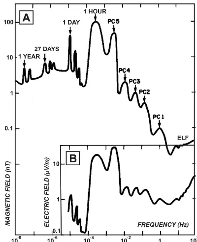
val-Figure 1. Natural variations of the electric and magnetic fields
(from Serson, 1973).
ues of the measured variations of the electric field compared to the so-called contact potential arising at the interface of the contact of the electrode with the environment. Figure 1 shows the evaluation of the level of natural variations of the electric and magnetic fields, taken from Serson (1973). Be-cause of the complex electrochemical reactions occurring at the electrode surface, the magnitude of the contact potential, and especially its instability, they both essentially depend on a number of physical and chemical processes in the environ-ment.
The first method to reduce the influence of the contact potential difference instability, that is, increasing the signal– noise ratio in electrical measurements, is to increase the dis-tance between the measuring electrodes (length of electrical lines). This solution gave a positive result under deep MT which allowed estimates of conductivity up to the Earth’s mantle (Egbert and Booker, 1992; Semenov et al., 2008). But, it is not always applicable, especially when working in populated or mountainous areas where you cannot expand the long lines for the necessary long time. Another approach is to improve the quality of the measuring electrodes and electrical channels of MT stations by reducing the level of their own noise, increasing sensitivity and temporal stability. This paper is dedicated to this second approach implementa-tion.
Phoenix 1.72 mV 1.9 k
GISCO 0.88 mV 1.3 k
BGP 3.30 mV 1.04 k
LEMI 0.06 mV (selected pair) 0.5 k
2 Analysis, design and implementation of an electrical measurement channel
For the measurements of the electric field in geophysics, the so-called “non-polarized” electrodes are used. By this it is as-sumed that these electrodes do not chemically interact with the environment and provide low drift during long-run mea-surements of the electric field, which is not true. In reality, between the electrode surface and the environment in which the electrode is immersed, there is always electrochemical in-teraction creating the so-called polarization potential of the electrode. Measuring electric fields as the potential differ-ence between two electrodes, we always have at the elec-trode pair output the voltage equal to the sum of the useful signal proportional to the electric field value in the environ-ment and difference of such polarization potentials. By this the second term in practice is much greater than the useful signal. There are many works devoted to the investigation of the electrochemical interaction of the electrode with the surrounding conducting medium and to the methods to de-crease the polarization potentials (e.g. Frumkin et al., 1952; Conway, 1965; Yu and Ji, 1993). As an issue of their find-ing, we may state that in order to minimize the polariza-tion effect, the electrodes have to be manufactured using the metal immersed in its salt, and then the salt has to be in contact with the ground. The most common in geophysical practice are the electrodes from the following manufacturers: GMC (Ag–AgCl), Phoenix Geophysics (Pb–PbCl), GISCO (Cu–CuSO4) and BGP (Pb–PbCl), and, recently, LEMI (Cu–
CuSO4). For these electrodes the magnitude of the contact
Figure 2. Long-term drift of the potential difference of selected
pairs of electrodes. Here: Drms – root mean square error;M– zero line shift. DU is averaged for 1-day dispersion.
of magnitude of the measured daily variations of the electric field, which is difficult to realize in practice.
Recently new regulations in Europe require the elimina-tion of lead and its composites from use. This fostered the resumption of the study of other possible materials and struc-tures of the electrodes. As a starting point, the electrode on the basis of copper and copper sulfate (Cu–CuSO4) was
adopted. The shortcomings of such a construction of a non-polarized electrode based on the combination of Cu–CuSO4
were studied (Korepanov and Svenson, 2007) and as a result a new improved design of a non-polarized LEMI-701 elec-trode was proposed (LCISR, 2014).
Geophysical electrodes LEMI-701, except for environ-mental safety (Cu salt works as fertilizer), possess signifi-cant advantages as compared with lead electrodes. For com-parison, the measured noise level of randomly selected pairs of electrodes LEMI-701 is ∼20 nV at 1 Hz vs. 0.4 mV for Pb–PbCl (Petiau, 2000). For matched pairs after calibration and a specially designed selection procedure, average drift over 4 months was 50–60 µV for LEMI-701 (Korepanov and Svenson, 2007), see Fig. 2, against 1 mV month−1 for Pb– PbCl electrodes (Petiau, 2000). With such a level of the drift, the requirements for the electrode line length become much more practical: referring again to Fig. 1, we may conclude that the baseline about 50–60 m is already admissible for getting the signal–noise ratio for diurnal variations close to unity.
Apart from the electrodes, the parameters of the used mea-suring equipment – an electrometer – also play an important role in improving the quality of the electric field measure-ment. A number of specific requirements should be taken into account in such an instrument design because it must
Figure 3. Functional diagram of the LEMI-420 channel for
electri-cal measurements. Here:U1,U2,Ug– input voltage; LP – circuit which protects against lightning-induced large voltage; OP – opera-tional amplifier; ADC – analogue/digital converter; RVS – reference voltage source; MC – microcontroller; GI – galvanic isolation; PSU – power supply unit.
measure signals with periods ranging from fractions of sec-onds to about 100 000 s with minimal error in field conditions at sufficiently large environmental temperature variations. In this the very important requirement is the absence of the cur-rents in the input circuits – if they are flowing through the electrodes and the ground, they are infringing the electro-chemical equilibrium at the electrode–environment contact surface. Simultaneous demands to transmit practically DC signals and input current minimization greatly complicate the task of electrometer development. To solve this task, the sophisticated technology of input circuit galvanic isolation while simultaneously meeting the requirements of high input resistance is used. For this, as Fig. 1 shows, the sensitivity threshold of the electrometer should not exceed 0.1 µV m−1 in order to provide sufficient accuracy. Typically the length of the measuring line is selected in the range of 50 to 200 m, which gives a minimum input signal level of about 0.05 mV, while soil resistance can reach up to several hundred kohm (for frozen ground). Depending on the soil resistance and the electrode quality, the initial level of the input signal can reach hundreds of mV; we will reserve a maximum value equal to 1 V. Also, as much as possible, low power consumption is an essential requirement.
Last but not least is the necessity to have the protection of input stages from nearby lightning occurring often during the field season – the long electric line presents an excellent an-tenna to create large voltages at its output at nearby lightning discharge.
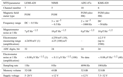
ad-Magnetic field
FGM FGM FGM (also FGM (also
meter type IM) IM)
Frequency range DC−0.5 Hz 3×10
−5 2×10⁻⁵ DC
−0.5 Hz −1000 Hz −50 kHz
Magnetometer
7 pT Hz−1/2 10 pT Hz−1/2 0 pT Hz−1/2 10 pT Hz−1/2 noise at 1 Hz
Electrometer
±2450 mV (1)
±250 mV (10),
–
±2.5 V
measuring range ±25 (100) mV (up to
(amplification) 2500)
ADC digits, bit 32 24 24 24
Electrometer
<0.08 µV Hz−1/2(1) <0.11 µV Hz−1/2(100) No data <0.08 µV Hz−1/2(40) noise at 1 Hz
(amplification)
Sampling rate 1 Hz 8 Hz 4096 Hz 100 kHz
Memory volume 32 GB 4 GB 32 GB 32 GB
Supply voltage 5–28 V +12 V +12 V 7.5–32 V
vantages of this design: the possibility to use a low-pass dig-ital filter with the desired frequency band and suppression factor, and to change the channel gain with a corresponding decrease in the input voltage operating range. Another ad-vantage is the compensator absence: having the amplification factor only unity, this allows covering of all really possible initial shifts of input voltage, and this also helps to reduce the own noise level at low frequencies. Reduction of power consumption is achieved by using both galvanic separation in the digital part of the circuit and galvanic isolation in the power supply. In this case the electrode potentials are mea-sured on relatively galvanically isolated ground.
Table 2 shows the comparative parameters of the MT sta-tions of the leading producers at the world market. We se-lected MT stations with a flux-gate magnetometer (FGM) only because we concentrate our study on the instruments for a long-period survey.
3 Field test results
To confirm the advantages of MT station LEMI-420 electric channels, the comparative field tests with a previous version of MT station LEMI-417 were made at the site near the vil-lage of Kobaky, Ivano-Frankivsk region.
Special attention was paid to the electrode installation, which is necessary for long-term measurements. First, the proper selection of places where the electrodes have to be buried was made: as far as possible, similar places for the
ar-Figure 4. Electric channel setting.
rangement of two electrodes comprising one measuring line were found using the following principal requirements: the same soil composition and orographic features (i.e. hill–hill or valley–valley, under the tree–under the tree, etc.) and es-pecially moisture conditions. The setting of the LEMI-420 and LEMI-417 electrical lines is presented in Fig. 4.
Figure 5. Electrode installation in operation position: (a) long-term
and (b) short-term.
ways to install the electrodes at field works: “bottom up” for long-term installations more than 1 week (see Fig. 5a), and in a tilted position for a short time (see Fig. 5b). When prepar-ing installation, the suspension has to be prepared first: it is made by mixing the made ground taken from the installation place and 10 % CuSO4solution in enough quantity to cover
the electrode.
The advantages of bottom-up installation are, first, that the surrounding soil in this position with time is permanently in good contact with the sensitive part of the electrode – porous partition (opposite to the cable part in Fig. 5) – and in a tilted position, the soil, though it makes better contact with the partition than in a direct position, may come off this part with time. For long-term installation it is recommended, af-ter burying the electrode in the ground, to pour 10 % CuSO4
solution on this place. Taking into account that Cu salt works as fertilizer, this will not spoil the environment, in contrast to the salt solution used for Cl-based electrodes as above. For sandy soil, a special arrangement may be recommended if long-term installation is planned: the electrode is installed again in a bottom-up position, not directly in the ground, but in a plastic bucket open from above. This will save poured liquid and maintain lower resistance of the soil.
In our experiment, because the soil was clayish and the measurement time was rather short, we used the installa-tion shown in Fig. 5b. To verify the installainstalla-tion reliability, the electrode pair resistance was checked. In this it is very important, as said above, to avoid creating currents flowing through the electrodes. For this a voltmeter with input resis-tance≥10 Mand 10 µV resolution and a reference resistor have to be used. First, the voltmeter has to be coupled to the output wires of electrodes and the voltageU1measured (see
Fig. 6). Then the reference resistorR=3 kis connected for a short time to both electrode outputs and the voltageU2is
measured. The value of the transient resistance Rl of
elec-trodes to ground and soil was calculated as
Figure 6. Electrode resistance measurement diagram.
Rl=
R (U1−U2)
U2
,
with U1=40 mV, U2=10 mV, and R=3 k; we get
Rl=9 k, which confirmed rather moderate soil resistance.
Use of this method of resistance measurement may not al-ways give good results. It does not work properly in areas with a high electrical noise level, such as large cities, places near electric power lines, and routes of electric trains. On the other hand, it is not possible to obtain high-quality data-carrying measurements in such noisy places; so, the success of this test may also be an indicator of a clean enough elec-tromagnetic environment.
The resulting noise spectra of electric channels for various modifications of stations are shown in Fig. 7. Here curves 1 and 2 reflect measured natural signal spectra along theXand Y components correspondingly; lower curves are noise lev-els measured with short-circuited inputs for former versions of MT stations (curves 3 and 4) and for the LEMI-420 one (curve 5) divided by the length of the electrical lines used in curves 1 and 2. As is seen, the instrumental noise of the stations under test is about the same at longer periods, but LEMI-420 has a considerably lower noise level at shorter pe-riods, which is very important: if we refer to Fig. 1 again, we may see that just in this range the signal level is much lower than for longer periods.
4 Conclusions
Figure 7. Power spectra of natural signals and instrumental noise levels. Here curves 1 and 2 are measured natural signal spectra along the
XandYcomponents correspondingly. Curves 3 and 4 – noise levels measured with short-circuited inputs for former versions of MT stations and (curve 5) for station LEMI-420, both divided by the same inter-electrode distance as for curves 1 and 2.
of the electric field meter was developed and tested. This newly created electrometer is included in the long-period magnetotelluric station LEMI-420. To confirm the benefits of MT station LEMI-420, its field tests were carried out and a comparison of the instrumental noise level power spectra confirmed its advantage.
Acknowledgements. The authors are grateful to V. Tregubenko for the assistance in field tests and the results discussion.
Edited by: L. Vazquez
References
Cagniard, L.: Basic theory of the magneto-telluric method of geo-physical prospecting, Geophysics, 18, 605–635, 1953.
Chave, A. D. and Jones, A. G.: The Magnetotelluric Method, in: Theory and Practice, Cambridge University Press, 2012. Conway, B.: Theory and Principles of electrode processes, Ronald
Press, New York, 1965.
Egbert, G. D. and Booker, J. R.: Very long period magnetotel-lurics at Tucson Observatory: Implications for mantle conductiv-ity, J. Geophys. Res., 97, 15113–15128, doi:10.1029/92JB01252, 1992.
Frumkin, A., Bagotsky, V., Iofa, Z., and Kabanov, V.: Kinetics of electrode processes, MGU, Moscow, 1952.
Korepanov, V. and Svenson, A.: High-precision non-polarized elec-trodes for geophysical prospecting, Naukova Dumka, Kiev, 2007. LCISR: httP://www.isr.lviv.ua (last access: 15 July 2015), 2014. Petiau, G.: Second generation of lead-lead chloride electrodes for
geophysical applications, Pure Appl. Geophys., 157, 351–382, 2000.
Semenov, V., Pek, J., Ádám, A., Jó´zwiak, W., Ladanivskyy, B., Logvinov, I. M., Pushkarev, P., Vozar, J., and Experimental Team of CEMES Project: Electrical Structure of the Upper Mantle Be-neath Central Europe: Results of the CEMES Project, Acta Geo-physica, 56, 957–981, doi:10.2478/s11600-008-0058-2, 2008. Serson, P.: Instrumentation for induction studies on land, Phys.
Earth Planet. Inter., 7, 313—322, 1973.
Simpson, F. and Bahr, K.: Practical Magnetotellurics, Cambride University Press, 2005.
Tikhonov, A. N.: About the determination of electric characteristics of deep layers of Earth’s crust, Rep. Acad. Sci. USSR, 73, 295– 297, 1950.