Published online February 5, 2015 (http://www.sciencepublishinggroup.com/j/ijepe) doi: 10.11648/j.ijepe.20150401.16
ISSN: 2326-957X (Print); ISSN: 2326-960X (Online)
Switching-off angle control for switched reluctance motor
using adaptive neural fuzzy inference system
Liu Zhi Jian
1, *, Nguyen Le Minh Tri
1, 3, Nguyen Le Thai
2, Phan Xuan Le
1, 21
Faculty of Electric Power Engineering, Kunming University of Science and technology, Kunming City, Yunnan Province, China
2
Faculty of Electric and Electronic Engineering, Tuy Hoa Industrial College, Tuy Hoa City, Phu Yen Province, Vietnam
3
Faculty of Electrical Engineering, Kien Giang Technology and Economics College, Kien Giang Province, Vietnam
Email address:
[email protected] (Liu Zhi Jian), [email protected] (N. L. M. Tri), [email protected] (N. L. Thai), [email protected] (P. X. Le)
To cite this article:
Liu Zhi Jian, Nguyen Le Minh Tri, Nguyen Le Thai, Phan Xuan Le. Switching-off Angle Control for Switched Reluctance Motor Using Adaptive Neural Fuzzy Inference System. International Journal of Energy and Power Engineering. Vol. 4, No. 1, 2015, pp. 39-45. doi: 10.11648/j.ijepe.20150401.16
Abstract:
Switched reluctance motors (SRM) have a wide range of applications in industries due to the special properties of this motor. However, because of its dynamical nonlinearities, so the problems control of SRM is complex. This paper proposed an adaptive intelligent controller for SRM with the aim to improve the ripple of torque. First, we use a fuzzy logic controller to control switch-off angle, and then proposes a new controller by means of Adaptive Neural Fuzzy Inference (ANFIS). Simulation results are given to show the efficacy of the proposed method.Keywords:
SRM, Fuzzy logic, ANFIS1. Introduction
The switched reluctance motor (SRM) has simple structure, low-cost, and robust motor that makes it suitable for variable speed and servo-type applications. Further, it has a simple converter and control requirements. Thus, SRM has received great attention in the drive industry. [1-4]
The disadvantages of SRM are the stepping nature and inherent nonlinear characteristics, which causes an undesired effect on bearing. If the problems can be solved, SRM can be an alternative to the other motors [5]. These nonlinear characteristics include the nonlinear torque function of current, rotor position and the magnetic saturation at certain operation regions.
There are two choices for reducing the torque ripple minimization that is improved the magnetic structure of the motor or improved motor controller [6]. In recent years, fuzzy logic combination with neural network to control nonlinear objects was developed strongly. Specially, that is the used of ANFIS to control switched reluctance motor [7, 8, 9, 10]. In [7] an adaptive neuro-fuzzy inference system (ANFIS) is used to estimate phase inductance. An Adaptive Neural Fuzzy Inference System also is used to develop a new model for SRM [8]. In [9], the authors studied the problems of speed control for switched reluctance motor by means of an adaptive
neuro-fuzzy controller. An adaptive neuro-fuzzy controller of switched reluctance motor is presented in [10].
From the reasons mentioned above, the ANFIS algorithm can be used to control of nonlinear systems is effective.
In this paper, we propose an ANFIS controller to control switching-off for SRM with the primary purpose is to reduce the torque ripple minimization. The remainder of the paper is organized as follows. Section 2 describes SRM model. The Switch-Off Controller for SRM is presented in section 3. Simulations are given in Section 4 and conclusions are summarized in Section 5.
2. SRM Model
In this Section, we present the principle of control switch-off and the theoretical basis of the SRM to provide a basis for process design calculations.
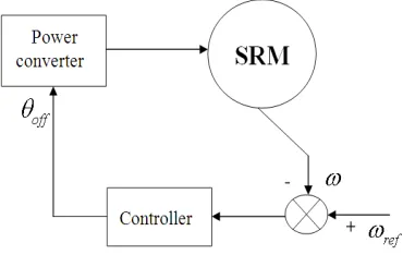
2.1. The Principle of Control Switch-Off
Figure 1. Schematic of Switch-off controller
2.2. Electromagnetic Equations
The switched reluctance motor has a simple structure, but the solution of its mathematical models is relatively difficult due to its dominant nonlinear behaviour.
The mathematical equations of switched reluctance motor are described as following
The voltage equation is:
( , ) j ( , , )
j s j r j j r r j
di
V R i i E i
dt
θ
ω θ
= + (1)
The motion equation is:
r
e m r L d
J T B T
dt
ω = − ω −
(2)
2 2
1
1 ( , ) 1
sin( )
2 2
e r k r
k dL i
T i i N ka kN
d
θ θ
θ
∞
=
= =
∑
(3)The linear inductance model is given
(
)
0 1
( r, ) kcos r
k
L N θ a a kNθ
∞
=
= −
∑
(4)Fourier expansion equation (4) and get to Level 3 (corresponding to the third harmonic)
Phase 1
( ) ( )
( )
1 0 1 2
3
( , ) cos cos 2
cos 3
= − −
−
r r r
r
L N a a N a N
a N
θ θ θ
θ (5)
Phase 2
( ) ( )
( )
2 0 1 2
3
( , ) cos cos 2
cos 3
= − − − −
− −
r r s r s
r s
L N a a N a N
a N
θ θ θ θ θ
θ θ (6)
Phase 3
( ) ( )
( )
3 0 1 2
3
( , ) cos 2 cos 2 2
cos 3 2
= − − − −
− −
r r s r s
r s
L N a a N a N
a N
θ θ θ θ θ
θ θ (7)
Phase j-th
(
)
(
)
3 0 1( , ) cos 1
j r k r s
k
L N θ a a kN θ j θ
=
= −
∑
− − (8)Write the general form equation inductance, the flux linkage, the moment of SRM motor at phase j-th only
consider the following third harmonic
(
)
3(
( ))
0 1
, , cos 1
=
= − − −
∑
j r j k r s j
k
N i a a kN j i
λ θ θ θ (9)
(
)
3(
( ))
2 1
1
, , sin
2 =
=
∑
− − ej r j j r k r s
k
T N θ i i N ka kN θ j iθ (10)
Where
Vj is the phase voltage j-th ij is the Phase current j-th
Rs is the phase winding resistance
θr is the shaft speed J is the moment of inertia
Bm is the friction
λj is the flux linked by the winding j-th TL is the torque load
Ns is the number of stator poles
Nr is the number of rotor poles
θ is the position of the rotor
θj is the position of the rotor j-th
θs is the phase current displacement angle Tej is the total torque j-th
In SRM drive, it is important to synchronize the stator phase excitation with the rotor position. Therefore, the information of rotor position is an essential for the proper switching operation. By synchronizing the appropriate rotor position with the exiting current in one phase the effectiveness of SRM can be achieved.[11]
Control method of switch-off angle is introduced for variable load, which is based on two command signals for switching-on and switching-off angle independently. According to the motor speed and load condition, a proper switching-on angle θ on is set at the cross point of negative slope of the sensor signal and the switching-on command signal Von as follows as
max
1 ( )
= − − +
on
on o a a
V V
θ θ θ θ (11)
The maximum switching-on angle is in the minimum inductance region. Thus, a fast build up of current is possible at the rated load. The minimum switching-on angle is in the increasing region of inductance. Therefore a smooth build up of current is possible at a light load with a smooth torque production. Similarly, the delay angle is set at the cross point of positive slope of the signal and the switching off command
signal
V
off asmax
( )
= off − +
off d o o
V
V
θ θ θ θ (12)
In addition, the dwell angle is the interval of switching-on and switching-off angles, which takes the form
= −
dwell off on
θ θ θ (13)
θon is the switching-on angles θoff is the switching-off angles
θo is the Overlap of phase flux linkages or inductances
θa is the Advance angle
θd,θdwell is the Current dwell angle
In SRM motor, through experiments showed that, with each different speed and torque of different loads, there will be a corresponding switch-off, at which the ripple of torque is the smallest.
3. Switch-Off Controller for SRM
This Section will present the design of fuzzy logic controller and then develop a new controller by means of Adaptive Neural Fuzzy Inference Systems (ANFIS)
3.1. Fuzzy Logic Controller
Fuzzy logic controllers are the one which is mainly used in system control for industries. The fuzzy logic controller has the following main functions as follows
Figure 2. Block diagram of Fuzzy Logic Controller system
(1) Fuzzification is the process of converting real scalar value in to membership fuzzy set values. In this paper Gaussian membership function is used for inputs and triangular membership function for output.
(2) Inference: The fuzzy inference decides how to process rules using fuzzy input. The inputs for the fuzzy controller will be error and change in error. The control signals will vary according to error and change in error. Once the fuzzy controller receives input the rule base is evaluated [12].
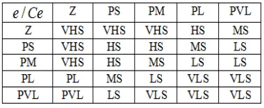
(3) Rule base Design: Basically a rule base is a linguistic controller, which is designed using IF THEN statements. Here we have two input conditions and one output response. Based on that, rules are designed for proper control of the system. The Figure 3 shows the rule base design for the speed control of Switched Reluctance Motor [13].
(4) Defuzzification: Defuzzification is the process of converting the degrees of membership of output linguistic variables with their linguistic terms in to crisp values. The defuzzification method used in this paper is centre of area which will change the switch-off angle of the controller accordingly.
Figure 3. Rule data base for Fuzzy Logic Controllers
3.2. ANFIS Controller
The Adaptive Neural Fuzzy Inference Systems is a kind of neural network which is based on Takagi–Sugeno fuzzy inference system. Since it integrates both neural networks and fuzzy logic principles, it has ability to capture the advantages of both in a single framework. Its inference system corresponds to a set of fuzzy IF–THEN rules that it is capable of learning to approximate nonlinear functions [14]. Hence, ANFIS is regarded to be a universal estimator [15].
Fuzzy if-then rules and how the radial basis function network relate to this kind of simplified ANFIS
For simplicity, we assume the fuzzy inference system under consideration has two inputs eω and deω/dt and one output f. Suppose that the rule base includes two fuzzy if-then rules of Takagi and Sugeno’s type [16, 15].
In this study using 5 set of fuzzy rule, such as:
1 1 1 1 1 1,
2 2 2 2 2 2
3 3 3 3 3 3
4 4 4 4 4 4
5 5 5 5 5 5
1 : ,
2 : ,
3 : ,
4 : ,
5 : , .
Rule if x is A and y is B then f p x q y r
Rule if x is A and y is B then f p x q y r
Rule if x is A and y is B then f p x q y r
Rule if x is A and y is B then f p x q y r
Rule if x is A and y is B then f p x q y r
= + +
= + +
= + +
= + +
= + +
For the training of the network, there is a forward pass and a backward pass. We now look at each layer in turn for the forward pass. The forward pass propagates the input vector through the network layer by layer. In the backward pass, the error is sent back through the network in a similar manner to back-propagation.
The corresponding equivalent ANFIS architecture is in as Figure 4.
The node functions in the same layer are of the same function family as described below:
- Layer 1: Every node in this layer is a square node with a node function.
( )
j
j
i A
O =µ x (14)
Where i=1÷2, j=1÷5; x is the input to node i and Aj is the linguistic label (small, large, etc.); associated with this node function. In other words j
i
O is the membership function of
Aj, and it specifies the degree to which the given x satisfies the quantifier Aj.
In this study we choose (14) to be bell-shaped with maximum equal to 1 and minimum equal to 0, such as (15) and (16).
( )
( )
21
1
= =
+ +
j j ij
A A b
ij ij x e e c a ω ω µ µ (15)
( )
21 1 = = + +
j j ij
B B b
ij ij de y dt de c dt a ω ω µ µ (16)
With
{
a
ij,b
ij,c
ij} is the parameter set. As the values of these parameters change, the Bell-shaped functions vary accordingly, thus exhibiting various forms of membership functions on linguistic label Aj, Bj. Parameters in this layer are referred to as premise parameters.- Layer 2: Every node in this layer is a circle node labeled II which multiplies the incoming signals and sends the product out, as in (17÷22).
( )
.( )
( )
. = =
j j j j
j A B A B
de
w x y e
dt
ω ω
µ µ µ µ (17)
( )
1 1 1 . = A B de w e dt ω ωµ µ (18)
( )
2 2 2 . = A B de w e dt ω ωµ µ (19)
( )
3 3 3 . = A B de w e dt ω ωµ µ (20)
( )
4 4 4 . = A B de w e dt ω ωµ µ (21)
( )
5 5 5 . = A B de w e dt ω ωµ µ (22)
Each node output represents the firing strength of a rule, (In fact, other T-norm operators that perform generalized AND can be used as the node function in this layer).
- Layer 3: Every node in this layer is a circle node labeled N. The i-th node calculates the ratio of the i-th rule’s firing strength to the sum of all rules’ firing strengths, as in (23):
1 2 3 4 5
= + + + + j j w w
w w w w w (23)
For convenience, outputs of this layer will be called normalized firing strengths
- Layer 4: Every node in this layer is a square node with a node function:
(
)
4= = + +
= + +
j j j j j j j
j j j j
O w f w p x q y r
de
w p e q r
dt
ω ω
(24)
Where wj is the output of layer 3, and {pj, qj, rj} is the
parameter set. Parameters in this layer will be referred to as consequent parameters.
4
1 1 1 1 1 1 1
4
2 2 2 2 2 2 2
4
3 3 3 3 3 3 3
4
4 4 4 4 4 4 4
4
5 5 5 5 5 5 5
= = + + = = + + = = + + = = + + = = + + de O w f w p e q r
dt de O w f w p e q r
dt de O w f w p e q r
dt de O w f w p e q r
dt de O w f w p e q r
dt ω ω ω ω ω ω ω ω ω ω (25)
- Layer 5 The single node in this layer is a circle node labeled E that computes the overall output as the summation of all incoming signals, i.e, as in (26):
5 5 1 ANF 1 w =
= = IS =
∑
j j jO f U f (26)
Where output signal of in layer 5 is f =θoff , shown in
Figure 4.
3.3. Hybrid Learning Algorithm
From the proposed ANFIS architecture in Figure 4, it is observed that given the values of premise parameters, the overall output can be expressed as a linear combinations of the consequent parameters. More precisely, the output f in Figure 4 can be rewritten as in (27).
1 1 2 2 3 3 4 4 5 5
= + + + +
f w f w f w f w f w f (27)
4. Simulation Results
used for our studies are given in Table 1.
Table 1. Switched Reluctance Motor Parameters
Symbol Parameters Value
m Mumber phase 3
Ns Number of stator poles 6 Nr Number of rotor poles 4 Imax Phase current 10(A) Uđm Phase terminal voltage 300(V) Rs Phase winding resistance 1.5(Ω) Lmax Maximum phase inductance 0.05(H) Lmin Minimum phase inductance 0.01(H) s Stator pole arc 300 r Rotor pole arc 300 J Moment of inertia 0.001(kgm2) Bm Friction 0.00007(Nm)/(rad/s)
Tload Moment load 3.0(Nm)
Then two different cases are conducted:
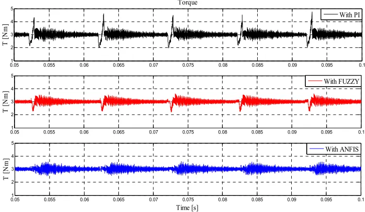
Case 1: We select the mode of SRM works at speed 500rpm, the characteristic speed of SRM is shown in Figure 5. The figure 6 gives the simulation results of the torque ripple of three different approaches. The black line shows the torque ripple when uses PI controller. The red line provides the torque ripple of SRM with fuzzy logic, and the blue line is the torque ripple of SRM under the ANFIS controller. The results in Figure 6 show that, the fuzzy logic controller achieves slightly better performance compared to PI controller. Nevertheless, the proposed method with ANFIS controller can obtain best performance.
0 0.1 0.2 0.3 0.4 0.5 0.6 0.7 0.8 0.9 1
0 100 200 300 400 500 600
Speed
Time [s]
n
[
rp
m
]
With ANFIS
Figure 5. The characteristic speed of SRM works at 500rpm.
0.05 0.055 0.06 0.065 0.07 0.075 0.08 0.085 0.09 0.095 0.1
1 2 3 4 5
Torque
T
[
N
m
]
0.05 0.055 0.06 0.065 0.07 0.075 0.08 0.085 0.09 0.095 0.1
1 2 3 4 5
T
[
N
m
]
0.051 0.055 0.06 0.065 0.07 0.075 0.08 0.085 0.09 0.095 0.1
2 3 4 5
Time [s]
T
[
N
m
]
With PI
With FUZZY
With ANFIS
Case 2: We select the mode of SRM is working at speed 2000 rpm, and we also use the parameters of the motor in Table 1. The characteristic speed of SRM is given as Figure 7.
Figure 8 shows that the simulation results of the torque ripple of three different approaches. The black line shows the torque ripple when use PI controller. The red line provides the torque ripple of SRM with fuzzy logic, and the blue line
is the torque ripple of SRM under ANFIS controller. Figure 8 also shows that the fuzzy logic controller achieves slightly better performance compared to PI controller, and the proposed method by using ANFIS controller can obtain best performance. Here, we can see that the proposed methods in this paper can provide overall improved performance compared to other methods.
0 0.1 0.2 0.3 0.4 0.5 0.6 0.7 0.8 0.9 1 0
200 400 600 800 1000 1200
Speed
Time [s]
n
[
rp
m
]
With ANFIS
Figure 7. The characteristic speed of SRM works at 1000 rpm.
0.05 0.055 0.06 0.065 0.07 0.075 0.08 1
2 3 4 5
Torque
T
[
N
m
]
0.05 0.055 0.06 0.065 0.07 0.075 0.08 1
2 3 4 5
T
[
N
m
]
0.05 0.055 0.06 0.065 0.07 0.075 0.08 1
2 3 4 5
Time [s]
T
[
N
m
]
With PI
With FUZZY
With ANFIS
Figure 8. The torque ripple of SRM works at 1000rpm
5. Conclusion
This article proposes hybrid ANFIS algorithm, its purpose to minimize the torque ripple of the switched reluctance motors. To see the effectiveness of ANFIS controller clearer, we also analyzed the classic controller, fuzzy controller and the finally develop an intelligent controller by using Adaptive
References
[1] Yasuharu Ohdachi, Yoshihiro Kawase, Yutaka Miura and Yoji Hayashi, “Optimum design of switched reluctance motors using dynamic finite element analysis,” IEEE Trans Magnet, Vol. 33, No. 2, pp.2033–2036, 1997.
[2] Perez GE, Ortiz PM, Ramirez HS, “Passivity-based control of switched reluctancemotors with nonlinear magnetic circuits,” IEEE Trans Control System Technol, Vol. 12, No. 3, pp.439–448, May 2004.
[3] McCann R, Islam M, “Application of a sliding-mode observer forposition and speed estimation in switched reluctance motor drives,” IEEE Trans Ind Appl, Vol. 37, No. 1, pp.51–58, 2001.
[4] Yamai H, Kaneda M, “Optimal switched reluctance motor drive forhydraulic pump unit,” Proc IEEE Int Conf Ind Appl, Italy, Rome, pp.1555–1562, 2000.
[5] R. Krishnan, Switched Reluctance Motor Drives, Boca Raton, FL:CRC Press, 2001.
[6] T. S. Chuang, and C. Pollock, “Robust speed control of a switched reluctance vector drive using variable structure approach,” IEEE Trans. on Industrial Electronics, vol. 44, no. 6, pp. 800–808, Dec. 1997.
[7] Ferhat Daldaban, Nurettin Ustkoyuncu, Kerim Guney, “Phase inductance estimation for switched reluctance motor using adaptive neuro-fuzzy inference system,” Energy Conversion and Management, pp.485–493, 2006.
[8] Wen Ding, Deliang Liang, “Modeling of a 6/4 Switched Reluctance Motor Using AdaptiveNeural Fuzzy Inference System,” IEEE Transactions on Magnetics, Vol. 44, No. 7, pp.1796-1804, July 2008.
[9] Hany M. Hasanien, “Speed Control of Switched Reluctance Motor Using an Adaptive Neuro-fuzzy Controller,” Proceedings of the World Congress on Engineering 2013 Vol II, pp. 1093-1096, July 2013.
[10] Ahmed Tahour, Hamza Abid, “Abdel Ghani Aissaoui, Adaptive Neuro-Fuzzy Controller of Switched Reluctance Motor,” Serbian Journal Of Electrical Engineering Vol. 4, No. 1, pp 23–34, June 2007.
[11] Jin-Woo Ahn “Torque Control", book edited by Moulay Tahar Lamchich, ISBN 978-953-307-428-3, pp201-252, February, 2011.
[12] S. Vijayan, S. Paramasivam, R. Arumugam, S. S. Dash, K. J. Poornaselvan, "A Practical approach to the Design and Implementation of Speed Controller for Switched Reluctance Motor Drive using Fuzzy Logic Controller,” Journal of Electrical Engineering, vol.58, No.1, pp. 39-46, 2007. [13] Gamal M. Hashem, Hany M. Hasanien, “Speed Control of
Switched Reluctance Motor Based on Fuzzy Logic Controller,” roceedings of the 14th International Middle East Power Systems Conference (MEPCON’10), Cairo University, Egypt, pp.288-292, 2010.
[14] J-S-R.Jang, C-T.Sun, E.Mizutani, “Neuro-fuzzy anh soft computing,” Prentice Hall Upper Saddle river, NJ 07458, 1997.
[15] A. Abraham, "Adaptation of Fuzzy Inference System Using Neural Learning,” Springer-Verlag Berlin Heidelberg, 2005. [16] T. Takagi and M. Sugeno, “Fuzzy identification of systems
and its applications to modeling and control,” IEEE transactions on systems, man, and cybernetics, Vol. SMC-15, No.1, 1985, pp. 116–132, January/February.