Baghdad Science Journal
Vol.14(1)2017
DOI:http://dx.doi.org/10.21123/bsj.2017.14.1.0219
Cache Coherence Protocol Design and Simulation Using IES
(I
nvalid
E
xclusive
read/write
S
hared
)
State
Luma Fayeq Jalil*
Maha Abdulkareem H. Al-Rawi**
Abeer Diaa Al-Nakshabandi***
*Department of Computer Sciences, University of Technology, Baghdad, Baghdad, Iraq. **Department of Computer Sciences, University of Technology, Baghdad, Baghdad, Iraq. ***Head of programmers oldest, Distribution office At Ministry of Electricity, Baghdad, Baghdad, Iraq.
E-mail:abeerdiaaphd@gmail.com
Received 25/ 5/2016 Accepted 26/7 /2016
This work is licensed under a Creative Commons Attribution-Non Commercial-No Derivatives 4.0 International License
Abstract
To improve the efficiency of a processor in recent multiprocessor systems to deal with data, cache memories are used to access data instead of main memory which reduces the latency of delay time. In such systems, when installing different caches in different processors in shared memory architecture, the difficulties appear when there is a need to maintain consistency between the cache memories of different processors. So, cache coherency protocol is very important in such kinds of system. MSI, MESI, MOSI, MOESI, etc.are the famous protocols to solve cache coherency problem.
We have proposed in this research integrating two states of MESI's cache coherence protocol which are Exclusive and Modified, which responds to a request from reading and writing at the same time and that are exclusive to these requests. Also back to the main memory from one of the other processor that has a modified state is removed in using a proposed protocol when it is invalidated as a result of writing to that location that has the same address because in all cases it depends on the latest value written and if back to memory is used to protect data from loss; preprocessing steps to IES protocol is used to maintain and saving data in main memory when it evict from the cache. All of this leads to increased processor efficiency by reducing access to main memory.
Key words: Cache Coherence Problem, Snooping Protocol, Directory-Based Cache
Protocols, MESI, Cache Simulator, Dev. C++, Multiprocessor, Shared Memory.
Introduction:
The difference between main memory and the processor speed may take a lot of processor cycles to get to
memories, which are either on chip or off-chip, used to improve latency and performance, are called cache memories [2].
High inconsistency which causes cache coherency problem might appear if there is any change in the shared data in a multiprocessor system having different processors with a different cache memories that share data in the main memory. Coherence between these caches is achieved through the application of two_hardware_based protocols which are snoopy and directory_based protocols [3, 4].
This paper gives the basic idea of how to simulate multi-level caches to implement IES protocol using DEV C++ language. To simulate caches, the number of cache levels and the parameters of a cache memory such as the "cache memory capacity" for each cache level, "the cache line size", "associativity", "the replacement policy", "the number of words per memory access", "the writing policy", etc. are determined. Finally, the
processor efficiency is calculated from either finding the input address in the caches to become "hit" or not finding that address which gets from t`he main memory to become "Miss".
The Basic Concepts in Caching:
The caching data exploiting the locality in memory hierarchies get the illusion of a large and fast memory. There are two types of locality that benefit memory [5]. In most programs, the same address of memory is used repeatedly for reading or writing by processor. So, temporal locality appears as a result of a high degree of locality in these programs. Another feature called spatial locality is that if a processor reads or writes a memory location then there is a probability to read or write nearby locations also. To exploit the second behavior, caches may operate by holding a group of neighboring data known as cache lines (also called cache blocks) [6,7]. Memory hierarchy illustrated in Figure 1:
Fig. 1: The Memory Hierarchy [1,2,3,5]
Cache Coherency:
Cache coherency is the consistency and validation of the data value in the caches of a multi core processor such that any reading of a memory location via any caches will
policy that writes in both main memory and cache to become valid [3]. The other is a Write back which is not written into main memory unless another cache needs that cache line [6].
Inconsistency that leads to incorrect execution causes a cache coherence problem. This problem appears if the data is updated by one processor without informing the others. Two basic protocols are used to eliminate this problem in memory system [9]:
a- Bus_Snooping Protocols
This protocol is used in a not scalable bus-based SMP system as broadcast medium where all the processor can observe all memory access by cache controller and then either invalidate or update the local cache content [10].
b- Directory_Based Protocols:
Either the directory is located centrally in the main memory of a multiprocessor system or may be distributed among caches. This directory is used as a tracker to a shared cache block between processors for maintaining coherence and consistent data which is recently updated. Therefore this protocol is preferred to use in a large scale shared memory multiprocessors [11].
MESI
Cache
Coherence
Protocol:
MESI protocol relies on four states to maintain consistency and coherence between the caches in a shared memory system. These states represent a shortcut to Modified, Exclusive, Shared and Invalid where each block in the cache has one of them according to the request of the processor. The states are illustrated as follows [5,8]:
a- "Modified":
The cache contains a copy which differs from that in the main memory and there are no other copies. Modified cache lines need to be written back to memory when they get evicted or invalidated. Modified may also be called Dirty Exclusive.
b-"Exclusive":
The cached copy is only in cache, which is the same in the main memory.
Exclusive may also be called Clean Exclusive.
c- "Shared":
The cached copy is valid in each of the cache and main memory, and at least one of the shared memory caches to this copy.
d-"Invalid":
This state indicates that the cache line does not have valid data.
(a)
(b)
Fig. 2: The State Transitions of MESI Cache Coherence Protocol (a) Detailed (b) abbreviation [1,5,7,8].
Methodology:
The steps of a proposed protocol using DEV C++ language are as follows:-
1. The Preprocessing steps of IES
cache coherence protocol are
Start
1
Use function for checking processor request (read or write) & Processor type (p1 or p2 or p3 or p4) &
Processor address of a sample program example
2Use function for convert decimal address to binary address
3
Use function to calculate tag & index& offset From binary number
4
Use direct mapped method in function to simulate caches in a three level depending on index and tag and offset of all
addresses probability as a subset of a main memory
All levels of caches lie in a temporary position before beginning execution of a sample program
5
Simulate 4 caches in level1 that contain 8 tag (3-bit), 4 index (2-bit), 8 offset (3-bit) From 8-bit of main memory address (256 byte)
6
Simulate 4 caches in level2 that contain 4 tag (2-bit), 8 index (3-bit), 8 offset (3-bit)
That receives the eviction of cache line from level1 caches that have the same index with different tag
7
Simulate shared cache in level 3 that contain 2 tag (1-bit) and 16 index (4-bit), 8 offset (3-bit) That received the eviction of cache line from level2 cache
That have the same index with different tag
*
8
Construct a directory in main memory that will be shared among all caches in level1 and level2 This directory used as a tracker of shared caches and contains all the data and states of the last write that write in
cache level1
9
check the addresses of a sample program starting from The first
serial no of programs continue until The last of the serial number
*
If there exists Addresses that Have Same index of different tag
yes
1 2
Evict the addresses to the caches in level2 if addresses in level1 have
same index and does not exists in level2 otherwise evict to the level3 Otherwise evict to main memory if cannot locate in level 2 & level3
No
1 0
construct a directory in main memory that will be used as a tracker of
shared cache, suppose that at first time all data value=0 and all states=”I”
1 1
Construct a cache line in level1 cache According to incoming address If the line not found in all 3 level of four caches
1 3
Check state of incoming address according to propsed Protocol to the caches in level1 or level2 or level3 depending on existence of address
Continue addresses 1
4 Update data and state of directory
Yes
1 6
Calculate final hit ratio & miss ratio Hit all = Hit in Level1 + Hit in Level2 + Hit in Level3
Miss all = 1 – Hit all
Hit ratio=(total hit/total address) * 100 Miss ratio = 1 – hit ratio
End 1
5
calculate Hit and Miss ratio according to the addresses and protocol in l1 & l2 & l3 and note that
Hit in address if incoming address is found in cache line although it is an Invalid state and Miss in protocol if incoming address is not found in cache line and create new line within Invalid state
NO
2 IES (Invalid, Exclusive read/write, Shared) Cache Coherence Protocol:
2.1 Cache Organization Using a Direct Mapped Method
At
the beginning work in this research, the four caches in level 1, the four caches in level 2 and the shared cache in level 3 are simulated by using a direct mapped method taking advantage of spatial locality as follow:-Suppose memory address = 256 [8-bit to represent the main memory address]. Level1 cache has 3-bit represent tag, 2-bit represent index, 3-2-bit represent offset Level2 cache has 2-bit represent tag, 3-bit represent index, 3-3-bit represent offset Level3 shared cache has 1-bit represent tag, 4-bit represent index, 3-bit represent offset
Main memory blocks are assigned to the lines of a cache mapped into one and only cache line as a result of a direct mapping method as in Table 1 where 𝑚 represents number of lines in the cache and s bits specify one of 2𝑠 blocks of main memory.
Table 2, Table 3 and Table 4 illustrate the assignment of a main memory blocks to the lines of caches in level1, level2 and level3 respectively as it is generally shown in Table1:
Table 1: Main Memory Blocks Assigned to Cache Line in General
Cache line
Main memory blocks assigned
0 0, 𝑚, 2𝑚, … . , 2𝑠− 𝑚
1 0, 𝑚 + 1, 2𝑚 + 1, … . , 2𝑠− 𝑚 + 1 .
m-1 𝑚 − 1, 2𝑚 − 1, 3𝑚 − 1, … . , 2𝑠− 1
Table 2: Main Memory Blocks Assigned to Cache Line in Level1
Cache lines at level1
Main memory blocks assigned
0 0, 4, 8, 12, 16, 20, 24, 28
1 1, 5, 9, 13, 17, 21, 25, 29
2 2, 6, 10, 14, 18, 22, 26, 30
3 3, 7, 11, 15, 19, 23, 27, 31
Table 3: Main Memory Blocks
Assigned to Cache Line inLevel2
Cache lines at level2
Main memory blocks assigned
0 0, 8, 16, 24
1 1, 9, 17, 25
. .
7 7, 15, 23, 31
Table 4: Main Memory Blocks Assigned to Cache Line in Level3
Cache lines at level3
Main memory blocks assigned
0 0, 16
1 1, 17
. .
15 15, 31
2.2 IES Cache Coherence Protocol State Diagram
IES stands for the state of each cache line at any time. A cache line in each cache can be in one of the following states:-
Invalid: The block has been invalidated
(possibly on the request of someone else)
Exclusive Read/Write: one processor
has data and it is dirty which must respond to any write request in case of write. But in case of read it is clean that one processor has data and no need to inform others about further changes.
Shared: up-to-date the cached in more
Invalid Shared
Exclusive R/W
If all other states are “I” In caches of
level1
RME
Get data from Main memory
RMS
read data from Shared cache
WME Yes
Local read
In
va
lid
at
e
Local write SHI
RH WH
SH
R
Remote read
Local read Local write
SHI
Remote write
Remote write
W
H
Update state and data in directory
Record name of shared caches
in directory
Local read (RH) If other
Cache states are Valid Update shared cache
Name In directory
Record the stare & name of other cache
as shared in directory Yes
No
Local write
Invalidate
NO
Co
m
m
it
Fig. 4: IES Cache Coherence Protocol State Diagram
The abbreviate symbols of the buses are as follow:
Bus transaction: Events:
RH = Read Hit, RMS = Read Miss Shared, RME = Read Miss Exclusive
WH = Write Hit, WM = Write Miss,
WME = Write Miss Exclusive
SHR = Snoop Hit on Read, SHI = Snoop Hit on Invalidate.
Measuring Cache Performance:
Time CPU lapses in the implementation of the program as well as in waiting inside the memory, so CPU time is calculated as in the following equations [2]:𝑪𝑷𝑼 𝒕𝒊𝒎𝒆
= (𝑪𝑷𝑼 𝒆𝒙𝒆𝒄𝒖𝒕𝒊𝒐𝒏 𝒄𝒍𝒐𝒄𝒌 𝒄𝒚𝒄𝒍𝒆𝒔 + 𝑴𝒆𝒎𝒐𝒓𝒚 𝒔𝒕𝒂𝒍𝒍 𝒄𝒍𝒐𝒄𝒌 𝒄𝒚𝒄𝒍𝒆𝒔) ∗ 𝒄𝒍𝒐𝒄𝒌 𝒄𝒚𝒄𝒍𝒆 𝒕𝒊𝒎𝒆 − −(𝟏)
𝑪𝑷𝑼 𝒕𝒊𝒎𝒆 =𝑰𝑪
∗(𝑪𝑷𝑰𝑬𝒙𝒆𝒄𝒖𝒕𝒊𝒐𝒏
+𝑴𝒆𝒎 𝑨𝒄𝒄𝒆𝒔𝒔
𝑰𝒏𝒔𝒕. ∗ 𝑴𝒊𝒔𝒔 𝒓𝒂𝒕𝒆
∗ 𝑴𝒊𝒔𝒔 𝒑𝒆𝒏𝒂𝒍𝒊𝒕𝒚)
∗ 𝒄𝒚𝒄𝒍𝒆 𝒕𝒊𝒎𝒆 − −(𝟐)
𝑪𝑷𝑼 𝒕𝒊𝒎𝒆 =𝑰𝑪
∗(𝑨𝑳𝑼𝑶𝑷𝑺
𝑰𝒏𝒔𝒕. ∗ 𝑪𝑷𝑰𝑨𝑳𝑼𝑶𝑷𝑺
+𝑴𝒆𝒎 𝑨𝒄𝒄𝒆𝒔𝒔
𝑰𝒏𝒔𝒕𝒓𝒖𝒄𝒕𝒊𝒐𝒏∗ 𝑨𝑴𝑨𝑻)
∗ 𝒄𝒚𝒄𝒍𝒆 𝒕𝒊𝒎𝒆− −(𝟑)
𝐀𝐌𝐀𝐓 = 𝑳𝟏 𝑯𝒊𝒕 𝒕𝒊𝒎𝒆 ∗ 𝑳𝟏 𝑯𝒊𝒕 𝒓𝒂𝒕𝒆 + 𝑳𝟏 𝑴𝒊𝒔𝒔 𝒑𝒆𝒏𝒂𝒍𝒊𝒕𝒚 ∗ 𝑳𝟏 𝒎𝒊𝒔𝒔 𝒓𝒂𝒕𝒆 − − (𝟒)
𝑳𝟏 𝑴𝒊𝒔𝒔 𝒑𝒆𝒏𝒂𝒍𝒊𝒕𝒚 =
𝑨𝒄𝒄𝒆𝒔𝒔 𝒕𝒊𝒎𝒆 𝒐𝒇 𝑳𝟐 = 𝑳𝟐 𝑯𝒊𝒕 𝒕𝒊𝒎𝒆 ∗ 𝑳𝟐 𝑯𝒊𝒕 𝒓𝒂𝒕𝒆 + 𝑳𝟐 𝑴𝒊𝒔𝒔 𝒑𝒆𝒏𝒂𝒍𝒊𝒕𝒚 ∗ 𝑳𝟐 𝑴𝒊𝒔𝒔 𝒓𝒂𝒕𝒆 − −(𝟓)
𝑳𝟐 𝑴𝒊𝒔𝒔 𝒑𝒆𝒏𝒂𝒍𝒊𝒕𝒚 =
𝑳𝟑 𝑴𝒊𝒔𝒔 𝒑𝒆𝒏𝒂𝒍𝒊𝒕𝒚 = 𝑨𝒄𝒄𝒆𝒔𝒔 𝒕𝒊𝒎𝒆 𝒐𝒇 𝑴𝒂𝒊𝒏 𝑴𝒆𝒎𝒐𝒓𝒚 − −(𝟕) 𝐀𝐌𝐀𝐓 = 𝑳𝟏 𝒉𝒊𝒕 𝒕𝒊𝒎𝒆 ∗ 𝑳𝟏 𝑯𝒊𝒕 𝒓𝒂𝒕𝒆 + (𝑳𝟐 𝑯𝒊𝒕 𝒕𝒊𝒎𝒆 ∗ 𝑳𝟐 𝑯𝒊𝒕 𝒓𝒂𝒕𝒆 + (𝑳𝟑 𝑯𝒊𝒕 𝒕𝒊𝒎𝒆 ∗ 𝑳𝟑 𝑯𝒊𝒕 𝒓𝒂𝒕𝒆 + 𝑨𝒄𝒄𝒆𝒔𝒔 𝒕𝒊𝒎𝒆 𝒐𝒇 𝑴𝒂𝒊𝒏 𝑴𝒆𝒎𝒐𝒓𝒚 ∗ 𝑳𝟑 𝑴𝒊𝒔𝒔 𝒓𝒂𝒕𝒆) ∗ 𝑳𝟐 𝑴𝒊𝒔𝒔 𝒓𝒂𝒕𝒆) ∗ 𝑳𝟏 𝑴𝒊𝒔𝒔 𝒓𝒂𝒕𝒆 − −(𝟖) Where 𝑰𝑪 = 𝑰𝒏𝒔𝒕𝒓𝒖𝒄𝒕𝒊𝒐𝒏 𝑪𝒐𝒖𝒏𝒕𝒆𝒓 𝑪𝑷𝑰 = 𝑪𝒍𝒐𝒄𝒌 𝑪𝒚𝒄𝒍𝒆 𝑷𝒆𝒓 𝑰𝒏𝒔𝒕𝒓𝒖𝒄𝒕𝒊𝒐𝒏 𝑨𝑴𝑨𝑻 = 𝑨𝒗𝒆𝒓𝒂𝒈𝒆 𝑴𝒆𝒎𝒐𝒓𝒚 𝑨𝒄𝒄𝒆𝒔𝒔 𝑻𝒊𝒎𝒆
The Experimental Result Using
DEV C++ Language
1. Binary Representation
Binary representation is one of a necessary preprocessing steps used to gain tag and index and offset of each decimal input address so as to facilitate the work of a mapping algorithm as in Table 5
Table 5: Binary Representation of Input Addresses Using a Proposed Protocol
address representation cache level1 cache level2 cache level3 Seq binary no no tag index offset Tag index offset tag index offset
1 01000110 70 2 0 6 1 0 6 0 8 6
2 01000110 70 2 0 6 1 0 6 0 8 6
3 01000110 70 2 0 6 1 0 6 0 8 6
4 00100011 35 1 0 3 0 4 3 0 4 3
5 11100110 230 7 0 6 3 4 6 1 12 6
6 10100100 164 5 0 4 2 4 4 1 4 4
7 00101001 41 1 1 1 0 5 1 0 5 1
8 01000110 70 2 0 6 1 0 6 0 8 6
9 01000110 70 2 0 6 1 0 6 0 8 6
10 00110100 52 1 2 4 0 6 4 0 6 4
11 11100110 230 7 0 6 3 4 6 1 12 6
12 01100100 100 3 0 4 1 4 4 0 12 4
13 11000001 193 6 0 1 3 0 1 1 8 1
14 11000001 193 6 0 1 3 0 1 1 8 1
15 00101001 41 1 1 1 0 5 1 0 5 1
16 11000001 193 6 0 1 3 0 1 1 8 1
17 01100100 100 3 0 4 1 4 4 0 12 4
18 11000001 193 6 0 1 3 0 1 1 8 1
2. Cache Simulation
The caches are simuled by using a direct mapped method in all level of caches according to an input address of a sample program (Table 6).
Table 6: Cache Simulation Using Direct Mapping in All Level Using IES Protocol
Simulation of Cache 1 in Level1 Index 103 102 101 100 99 98 97 96 0 47 46 45 44 43 42 41 40 1 55 54 53 52 51 50 49 48 2
Simulation of Cache 2 in Level1 Index 199 198 197 196 195 194 193 192 0
Simulation of Cache 3 in Level1 Index 103 102 101 100 99 98 97 96 0 47 46 45 44 43 42 41 40 1
Simulation of Cache 4 in Level1 Index
Simulation of Cache 1 in Level2 Index 71 70 69 68 67 66 65 64 0 39 38 37 36 35 34 33 32 4
Simulation of Cache 2 in Level2 Index 71 70 69 68 67 66 65 64 0 167 166 165 164 163 162 161 160 4
Simulation of Cache 3 in Level2 Index 71 70 69 68 67 66 65 64 0
Simulation of Cache 4 in Level2 Index 71 70 69 68 67 66 65 64 0 231 230 229 228 227 226 225 224 4
Simulation of a shared cache in Level3 Index 199 198 197 196 195 194 193 192 8 231 230 229 228 227 226 225 224 12
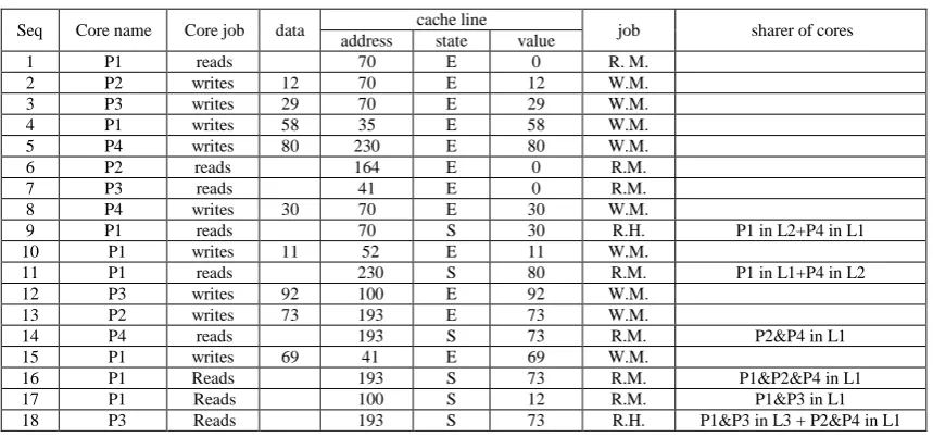
3. IES Cache Coherence Protocol Result
70, the state is translated from "I" to "E" because the address is not found in the all levels of caches and as a result, the cache line that contain address gets by a
read miss from main memory. All the next steps of the program are applied using the protocol in the same way.
Table 7: The Results of a Proposed Protocol on a Sample Program
Seq Core name Core job data cache line job sharer of cores address state value
1 P1 reads 70 E 0 R. M.
2 P2 writes 12 70 E 12 W.M.
3 P3 writes 29 70 E 29 W.M.
4 P1 writes 58 35 E 58 W.M.
5 P4 writes 80 230 E 80 W.M.
6 P2 reads 164 E 0 R.M.
7 P3 reads 41 E 0 R.M.
8 P4 writes 30 70 E 30 W.M.
9 P1 reads 70 S 30 R.H. P1 in L2+P4 in L1
10 P1 writes 11 52 E 11 W.M.
11 P1 reads 230 S 80 R.M. P1 in L1+P4 in L2
12 P3 writes 92 100 E 92 W.M.
13 P2 writes 73 193 E 73 W.M.
14 P4 reads 193 S 73 R.M. P2&P4 in L1
15 P1 writes 69 41 E 69 W.M.
16 P1 Reads 193 S 73 R.M. P1&P2&P4 in L1
17 P1 Reads 100 S 12 R.M. P1&P3 in L1
18 P3 Reads 193 S 73 R.H. P1&P3 in L3 + P2&P4 in L1
Note: The words of the abbreviation
symbols in table 7 are as follows:
R. M. = Read Miss,
W. M. = Write Miss,
R. H. = Read Hit
L1 = Level 1 of caches, L2 =Level2 of
caches, L3=Level3 of caches
4. Cache Performance Result
Cache performance can be measured by counting a program execution cycles that include cache Hit time and a memory stall cycles which result from cache misses. Depending on the clock speed of the central processor, it takes: 2 to 5 ns to access data in L1 cache, 10 to 20 ns to access data in L2 cache, 30 ns to access data in L3 cache, 50 to 100 ns to access data in Main Memory. Hit and miss ratio result from table6 and table7 are as follow:
Hit ratio in L1 = (no. of hit in level1/ total no. of address)*100 = (1/18)*100= 5.56
Miss ratio in L1 =100-Hit ratio =100-5.56= 94.44
Hit and Miss ratio in level2 is the same as in level. But miss ratio in
level3=100%
The Comparison between MESI
and Proposed Protocol:
The difference between MESI and IES protocol is that IES protocol merges modified and exclusive states to get one state named exclusive. In MESI protocol the state of incoming address in current processor becomes exclusive when the request of that processor is read and states of that address of all processors are invalid. While the request of a processor that enter the Exclusive state using IES protocol is either read or write.
use write back in the case of writing done by the rest cores.
In MESI cache coherence protocol there are several times that a write back is used. The number of a write back (WB) to the main memory that results from a remote write of other processor of MESI protocol are: - WB from the processor P2 in step 2
as a result of remote write of P3 in step3.
- WB from the processor P3 in step 3 as a result of remote write of P4 in step8.
By applying equation 2 𝑪𝑷𝑼 𝒕𝒊𝒎𝒆 =𝑰𝑪
∗(𝑪𝑷𝑰𝑬𝒙𝒆𝒄𝒖𝒕𝒊𝒐𝒏
+𝑴𝒆𝒎 𝑨𝒄𝒄𝒆𝒔𝒔
𝑰𝒏𝒔𝒕. ∗ 𝑴𝒊𝒔𝒔 𝒓𝒂𝒕𝒆
∗ 𝑴𝒊𝒔𝒔 𝒑𝒆𝒏𝒂𝒍𝒊𝒕𝒚)
∗ 𝒄𝒚𝒄𝒍𝒆 𝒕𝒊𝒎𝒆
The memory accesses are decreased as a result of reducing a write back to the main memory in using IES protocol. So, CPU performance is increased by reducing in CPU time.
A few differences between the two protocols show there because of the implementation of the program just a few steps. But the benefit of using this protocol appears when the program is implemented numerous steps.
Conclusion and Future Works:
Cache memory is a main component of memory hierarchy which plays an important role in the overall performance of the system and in the design of multicores. Multicores with shared memory architecture are used to satisfy increasing performance demands, which in turns are limited by cache coherence problem. Thus this survey focuses on the subject of the use of afuture work we try to increase size and the number of caches in level1 and level2 and to change in statesand using another mapping algorithm that have more associativity.
References:
[1] Thomas, R. & Gudula, R. 2013. Parallel Programming For Multicore and Cluster Systems, Published by Springer-Verlag Berlin and Heidelberg GmbH & Co. KG, Berlin. [2] David, A. P. & John, L. H. 2005.
Computer Organization and Design the Hardware / software interface, Elsevier Inc.
[3] David, A. P. & John, L. H. 2012. Computer Architecture A quantitative approach, Morgan Kaufmann is an imprint of Elsevier. [4] Azilah, S. and Najihah, B. R. F.
2014. Cache Coherence Protocols in Multi-Processor, International conference on Computer Science and Information Systems (ICSIS’2014) Oct 17-18, Dubai (UAE)
[5] William, S. 2010. Computer organization and architecture designing for performance, Printed in the United States of America by Pearson Education, Inc., Upper Saddle River, New Jersey, 07458. [6] Bryon, M. 2013. Real World
Multicore Embedded Systems, Elsevier Inc., United States of America.
[7] David C.; Jaswinder, S. P. and Anoop, G. 1997. Parallel Computer Architecture A Hardware/Software Approach, scalability, programmability, Morgan Kaufmann Publishers.
[9] Al-Hothali S. and Soomro S. et.al. 2010. Snoopy and Directory Based Cache Coherence Protocols: A Critical Analysis, Journal of Information & Communication Technology (Spring 2010) 4(1): 01-10.
[10] Alberto, R. and Alexandra, J. 2015. A Dual-Consistency Cache
Coherence Protocol, IEEE 29th International Parallel and Distributed Processing Symposium IPDPS, pp: 1119-1128, USA.
[11] Zaghloul, S. S., et.al. 2014. Index-Based Cache Coherence Protocol, David Publishing Company (DPC) Journal of communication and Computer 11:479-483.
يف طبارتلا لوكوتورب ةاكاحمو ميمصت
تلااح مادختساب ةيئبخملاةركاذلا
(
ريغ
،حلاص
يرصح
ةباتكلاو ةءارقلا يف
،
)كرتشم
ليلج قياف ىمل
*
يوارلا دومح ميركلا دبع اهم
**
يدنبشقنلا ءايض ريبع
***
* دعاسم ذاتسا ،
بوساحلا مولع مسق ،
ةيجولونكتلا ةعماجلا ،
دادغب ، دادغب .قارعلا ،
** دعاسم ذاتسا ،
بوساحلا مولع مسق ،
ةيجولونكتلا ةعماجلا ،
دادغب ، دادغب .
*** هاروتكدلا ةداهش لينل ثحبلا ةلحرم ةبلاط ،
مدقأ نيجمربم سيئر ،
ةقاطلا عيزوت ةرئاد ،
ءابرهكلا ةرازو ،
دادغب ، قارعلا .
:ةصلاخلا
ةلاح يف ةسيئرلا ةركاذلا نم لادب ةيئبخملا ركاوذلا مادختسا مت ةددعتملا تاجلاعملل ةثيدحلا ةمظنلاا يفيف ةبوعصلا نا لاا .تانايبلا ىلا لوصولاريخأت ليلقت للاخ نم جلاعملا ةءافك نيسحتل كلذو تانايبلا ىلا لوصولا ذلا فلتخم بيصنت اهيف متي يتلاو ةمظنلاا هذه نمكت ةدحاو ةركاذب كرتشت يتلا تاجلاعم ةدع يف ةيئبخملا ركاو
يرورضلا نم ببسلا اذهلو .ةددعتملا تاجلاعملا تاذ ةيئبخملا ركاوذلا تاركاذ نيب قباطتلا ىلع ظافحلا يف ظت يتلا ةلكشملا لحل ةروهشملا تلاوكوتوربلا عاونا نمو .ةئيبخملا ركاوذلا نيبام طبارتلا لوكوتورب مادختسا ره
يه ةيئبخملا ركاوذلا نيبام طبارتلا دنع MOESI, MOSI, MESI, MSI
.
دقل ةيرصحلا يه يتلاو يسيم ةيئبخملا ركاوذلا طبارت لوكوتورب تلااح نم نيتلاح جمد ثحبلا اذه يف انحرتقا
أو .تابلطلا هذهل ارصح دوعت يتلاو تقولا سفن يف ةباتكلاو ةءارقلا تابلطل بيجتست يتلاو ةلدعملاو ةلازا مت اضي
"ةلدعم" ةلاح يف نوكت يتلا تاجلاعملا ىدحا نم حرتقملا لوكوتوربلا مادختساب ةيسيئرلا ةركاذلا ىلا عوجرلا دامتعلاا متي لاوحلاا لك يف هنلا ناونعلا سفن هل رخا جلاعم نم ةباتكلا دنع "حلاص ريغ" ةلاح يف حبصت يتلاو اذاو اهتباتك متي يتلا ةريخلاا ةميقلا ىلع هناف عايضلا نم تانايبلا ىلع ظافحلل مدختسي ةركاذلا ىلا عوجرلا ناك
مادختساب اهجورخ دنع ةيسيئرلا ةركاذلا يف تانايبلا نزخو ظافتحلاا متي حرتقملا لوكوتوربلل ةقبسملا تاوطخلا
ةيئبخملا ةركاذلا نم ذلا ىلإ لوصولا نم دحلا قيرط نع جلاعملا ةءافك ةدايز ىلإ يدؤي اذه لك .
.ةركا
ةيحاتفملا تاملكلا :
ةــيئبخملا ةركاذلا يف طبارتلا ةلكـشم لوكوتورب ،
سلاا ــ ىلع مــئاقلا لوكوتوربلا ،علاطت
ليلدلا ، MESI ، ةاكاحم ةيئبخملا ةركاذلا ،
DEV C++ ،
ةددعتملا تاجلاعملا ،
![Fig. 2: The State Transitions of MESI Cache Coherence Protocol (a) Detailed (b) abbreviation [1,5,7,8]](https://thumb-us.123doks.com/thumbv2/123dok_us/195711.1513113/4.595.99.502.72.649/state-transitions-mesi-cache-coherence-protocol-detailed-abbreviation.webp)