4431
Efficient Data Recovery Techniques ON Mlc
Nand Flash Memory
Van-Dai Tran, Dong-Joo Park*
Abstract: Recently, flash memory has been used in most mobile devices due to its well-known benefits, such as high mobility, low power consumption, and fast data access. However, flash memory also has the drawbacks to overcome like erase-before-write and unsymmetrical read or write response time: one of the solutions is Flash Translation Layer (FTL). In addition, the data might be lost after power outage in the systems. Hence, recovery of data in this situation is of prime significance. One of the techniques is the error code correction (ECC), supplied with the flash device by the manufacturer and there have been schemes such as In-Page Backup, In-Block Backup, Hybrid Backup, A-PLR (Accumulation based Power Loss Recovery), HYFLUR (Hybrid FLUsh Recovery), and C-HYFLUR (Compression scheme for HYFLUR). Nevertheless, these techniques have the disadvantages of not only mapping information overhead but also recovery time. So, in this paper, we introduce two techniques based on the page leveling mapping and block leveling mapping methods using the spare area in FTL. The results show better recovery time and mapping information management overhead than those of previous schemes.
Index Terms: Flash memory, Data recovery, FTL, PLR, Spare area, Mapping information, and Mapping table. —————————— ——————————
1
INTRODUCTION
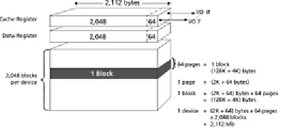
Flash memory is now widely used in most electronic devices as well as mobile devices, due to its advantages such as high mobility, fast data access and low power consumption. Nonetheless, it still has some disadvantages like erase-before-write or limited life cycle. In order to solve these drawbacks, Flash Translation Layer (FTL) was proposed. The structure of 2 GB MLC (multi-level cell) NAND flash memory is shown in Fig. 1.
Fig. 1 The structure of 2 GB MLC NAND flash
Three features of FTL [1], [2], [3], [4] are address mapping, wear-leveling, and garbage collection. Many FTL schemes have been proposed to address the restrictions and to improve the performance of flash memory. Though performance of flash memory has been improved together with FTL algorithms, when performing B-tree direct indexes, it suffers from the frequent overwriting flash memory activity to update nodes of them. Some of the B-tree versions have been proposed to address this problem by reducing the updating of B-tree with some main memory assets as buffers. However, if a power failure occurs, there will a problem of data loss because the records are stored in the main memory. Moreover, they utilize some main memory assets whose size is limited as specified by dissimilar embedded systems [5].
There are In-Page Backup, In-Block Backup, and Hybrid Backup schemes for the power off failure recovery. The first scheme, In-Page Backup, uses the backup area of every data page to save the parity ECC bits and the FTL management information. And as the general rule, backup area size is usually equal to 1/32 of the page size and this area is invisible to the user. Moreover, the redundant areas can be used for saving an information of mapping in a consistent way to program/read [7]. This technique uses redundant areas so it does not spend more cost. However, the controller reads all pages assets in the recovery process. So, it causes the recover lag resulting more time. The second scheme is In-Block Backup scheme: it utilizes a group of blocks called map blocks to record the backup data. When mapping the render information in flash memory, map blocks are prepared to keep the information of mapping. This technique also makes additional operations of writing, so it may give an additional overhead. Moreover, when power failure happens in flash memory, the recovery algorithm reads the map blocks which are made by mapping tables. So, in this technique the recovery response time is larger than that of In-Block Backup. The last scheme is Hybrid Backup scheme. It is an integration of both In-Page Backup and In-Block Backup for the cut down of recovery time and backup cost. Moreover, the updates write the page level mapping to all pages which is marked in the backup area for the corresponding pages. Page mapping tables are counted and stored in the block mapping after updating the block leveling map. In the recovery procedure, both the mappings of page leveling and block leveling are saved to the map blocks and the redundant areas of the general pages. So, this scheme improves the recovery procedure compared to In-Block Backup and decreases the recovery response time than that of In-Page Backup technique. In addition, in this technique the runtime backup overhead is very small compared to the In-Block Backup because the reading/writing response time for the backup area is unseen. Aforesaid techniques have disadvantages of the costs retrieving timetable and managing the mapping information. In this paper, we introduce two new techniques based on the page-level mapping and block-level mapping methods using spare area in FTL to address the disadvantages of PLR (Power Loss Recovery).
————————————————
• Van-Dai Tran is currently a Ph.D. candidate in Department of Computer Science and Engineering at Soongsil University, Seoul, Korea (06978). E-mail: [email protected]
• -Joo Park is currently a Professor in
4432
2
BACKGROUND
AND
RELATED
WORKS
2.1 ECC
The aim of the ECC is to attach additional condition to messages for event when a reading may find out errors and must restore all messages which are written. Block error code correction relies on data sub-sectors. Depending on the error fixing outline utilized, it uses a various amount of redundancies which is called the parity bit. In the Hamming algorithm, the inequality may compute the lowest parity bit as shown-in (1)
(1)
The parameters are: n code words, k bits information, and t bits error correction.
This lowest number is not always possible because the parity bits approximates to it. Moreover, the sub-sector size smaller than the square area size. To resolve the problem of collision for the flash die size BCH (Bose-Chaudhuri-Hocquenghem) and Reed Solomon [15] have been proposed, however Reed Solomon code needs more bits than the other. And that is the reason why flash memory adopts BCH to ECC [16]. Table 1 shows the comparison of these ECC algorithms.
Table 1
ECC Algorithms with Error Correlation Level [13] Correctable ECC
Error bit per sector
Bits required in the NAND flash spare area
Hamming Reed Solomon BCH
1 13 18 13
2 N/A 36 26
3 N/A 54 39
4 N/A 72 52
5 N/A 90 65
6 N/A 108 78
7 N/A 126 91
8 N/A 144 104
9 N/A 162 117
10 N/A 180 130
2.2 ECC for NAND Flash memory
Flash manager always apply the BCH algorithm to ECC. In addition, this algorithm requires 13 bits ECC code for repairing an error bit in 512 bytes sector. While the redundant size in flash increases linearly, the number of bits required to repair errors for the NAND flash memory may lead to exponential growth. In the MLC technique, an error correction process normally take place for each sector, so it needs ECC spare area code bits to keep the ECC code. The ECC algorithm using the new ECC bit recovering organization in the flash may get better. The LDPC (low density parity check) [14] has been introduced for flash memory systems, which can help the required code size in return appropriate to the algorithm processing time [17]. Even though a defect is detected and repaired with a smaller overhead, the code word will be long and require more space in the spare area than that of BCH. There are two techniques of ECC management: a conventional ECC management named C-ECM [13] and an in-page management idea known as IP-ECM [13]. While executing the correction of high-fault NAND flash memory, C-ECM utilizes efficaciously and holds short BCH codes together only for an effective and significant loss. IP-ECM obtains some
spaces as data area for saving a little page sector so that it can use more space for saving long BCH code in all sectors. And then sectors and BCH codes are stored with the same page, and sector data and ECC bit code are writable. This technique decreases number of sectors saved in a page to increase BCH bit codes storage space. These methods utilize the spare are as to save short ECC code bits. Clearly, IP-ECM has less effect on the demand of reducing the size of page. However, this problem is not important due to the current technical trend in SSD (Solid State Drive), which has the 8KB of page size in NAND flash memory to decrease the management overheads. Certainly, page collecting is a normal method to hold the overhead of a SSD using 10 NAND flash chips and to decrease the number of the FTL mapping table size.
2.3 PLR
4433
Fig. 2 Flush process
Three flush processes are shown in Fig. 2 by the timeline. SWF, URF, and MTF are implemented with reasonable guidelines. First, SWF operation is very clear. When the page is updated, the data are stored on other page. This situation requires changing the information of mapping as ppn (physical page number); in this method, the old ppn and the new ppn are changed which are stored in the spare area in the RAM. Second, URF operation is the process of saving both the old and the new ppn leading to certain pages of blocks known as MSB (Map information Store Block). As mentioned above, when a page is saved, ppn information is saved to RAM. This method needs 6 bytes for every ppn so that it may write 1365 ppns in 8 KB of memory. Thus, it saves 1365 pages for the information of mapping. Fig. 3 shows the URF operation.
Fig.3 URF operation
By using 8KB of full memory, the URF operation performed may save approximate 1.3 GB of flash memory. After URF operation all the information are stored onto the MSB pages. So, MSB is able to save approximate 30.8% of flash memory for the mapping information. MTF operation begins to save most of mapping information by storing the mapping table, which requires 3 bytes for writing ppn. Therefore, it is able to save 2730 ppns for 8 KB of pages. This operation happens when the MSB becomes full because of the URF operation. While the MTF performs, the new mapping is outcome for both the table of mapping and the MSB. Thus, this operation stores the new information of the mapping table, as shown in Fig. 4.
Fig. 4 MTF operation
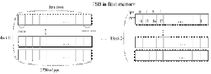
During MTF operation, ppn is written to pages. And the index pages turn lpn (logical page number) so that this method builds the table of mapping by scanning TSB (Table Store Block). Recovery procedure is consists of three instances. In order to restore of the information of mapping, it requires scanning the MSB pages created by the URF, the TSB created by the MTF, or scanning both. In the first instance, when a power outage happens, TSB cannot be created. Therefore, it
4434
3 PROPOSED
TECHNIQUES
3.1 Scheme based on Page-level Mapping method
This scheme uses the spare area classified into three parts: ECC part, mapping information, and reserved. This method is called SoPM (Scheme based on Page-level Mapping). Each page has a Logical Page Number (LPN) and the mapping information contains block information and allocation sequence number (ASN). Whilst a new page is written, LPN is also stored into the spare area replacing the previous one. Also this scheme uses memory register mapping information buffer for every write operation. When the power off failure occurs, the method will recover page mapping entry using the sequence of ASN. The restore process is executed on the block that has the highest ASN (mapping table sorted in descending order). The controller scans the accumulated page mapping entry from the beginning page to the last page. If the spare area in the block has proofs of writing, the page mapping entry are restored from LPN of that page. In other respects, the controller discovers the last update of the spare area using the page set. If the controller is not able to find out any more proof of writing, it means that the block is free. Fig. 5 displays the structure of the spare area and Fig. 6 shows the flowchart of SoPM.
ECC Block
information ASN
Mapping
information Reserved
Fig. 5 Structure of the spare area of SoPM
Fig. 6 The process of data recovery of SoPM
3.2 Scheme based on Block-level Mapping method
This scheme is based on Block-level mapping and uses the
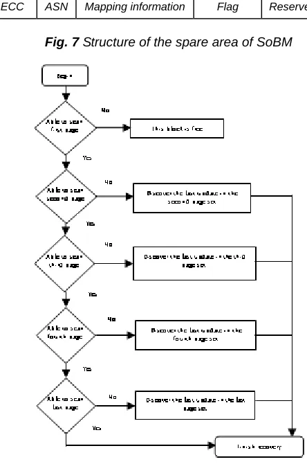
spare area divided into five parts: ECC, ASN, mapping information, Flag, and reserved. We call this method SoBM (Scheme based on Block-level Mapping). Each page has logical page number (LPN) for the page address restoration. All the blocks are sorted in descending order by ASNs. After reading the first page, if the controller finds the flag equal to 1, it means that the block is free. Otherwise, the block has programmed pages. During the recovery time, the FTL may be lower than the read operations from blocks and store the invalid page of the block called physical block number (PBN). Fig. 7 shows the structure of the spare area of SoBM and Fig. 8 indicates the recovery process of this scheme.
ECC ASN Mapping information Flag Reserved
Fig. 7 Structure of the spare area of SoBM
Fig. 8 The process of data recovery of SoBM
In the beginning of the procedure the controller reads the first page of every block to discover whether the data block has the same LPN page of block: if not, the mapping table is modified from the page of log block so it is a valid page. And then by comparing the ASN of data block with the log block, if the ASN of data block is not smaller than log block, the mapping table is updated from the page of data block using the related information with LBN of PBN in the spare area.
3.3 Recovery time calculation
4435 datasheet [18], and a 63 bytes in the space area is allocated
for ECC storage [6]. The device for these schemes have a 2 GB address space together with a 4KB page unit.
Table 2 indicates the NAND flash specification for the recovery time calculation.
Table 2
NAND Flash Specification [18]
Parameter NAND flash spec.
Page size 4096 bytes
Pages per block 128 pages
Number of blocks 4096 blocks
Capacity 2GB
Data transfer time from cell to
register (tD) 60 s
Program time 800 s
Block erase time 1.5 ms
Write/ Read time (tW/tR) 25 ns
Spare page size 128 bytes
We compute the recovery time for each scheme mentioned above.
1) For the In-Page Backup scheme:
Since the mapping information in the space areas is 4 bytes long, read operation time is
tR1 = tD + (tR x 4) = 60.1 (s) A block map table complete time is
tB1 = tR1 x 128 = 7,692.8 (s)
There are 4096 blocks in a device, and total recovery time is
Trec1 = tB1 x 4096 = 31,510 (ms)
2) For the In-Block Backup scheme: Read operation time is
tR2 = tD + (tR x 4096) = 162.4 (s) Total recovery time is
trec2 = tR2 x 128 x 4 = 83.15 (ms)
3) For the SoPM scheme:
In case all pages in a block are written, the complete processes should scan five representative pages. Since, the mapping store consists of 63 bytes, the read operation time is
tR3 = tD + (tR x 63) = 61.575 (s) And the block map table complete time is
tB3 = tR3 x 5 = 307.875 (s) The total recovery time is
Trec3 = tB3 x 4096 = 1,261 (ms)
4) For the SoBM scheme:
Block-level address is regular 10 bytes long, the read operation time is
tR4 = tD + ((tR x 4096) x 10)/4 = 316 (s)
And the controller is not able to restore the unique mapping table by ASNs. Comparing PBNs of each page of data blocks to find the last updated pages is necessary. In addition, the PBN has a block address and invalid page takes 4 bytes. Thus, the total recovery time is
trec4 = tR4 + ((tD + tR x 4) x 128x 10) = 77.24 (ms)
5) Discussion of the results:
We have compared our schemes with In-Page method and In-Block method which has more efficient time of power-loss recovery. The results show that our schemes are as good as In-Page in the read time and very competitive in the recovery time, as shown in Fig. 9 and Fig. 10.
Fig. 9 Read time comparison
Fig. 10 Recovery time comparison
4
CONCLUSION
In this paper, we introduce two novel techniques for data recovery using the spare area based on Page-level mapping method and Block-level mapping method, which are called SoPM and SoBM respectively. These algorithms can read the data by reducing the map table recovery time in the event of the power-loss without full recovery of data in the flash memory, so they enhance the performance of MLC NAND flash memory. In the future, we plan to apply these algorithms to the applications of flash memory and discover the efficiency of recovery performance.
5
REFERENCES
[1] T.-S. Chung, D.-J. Park, S. Park, D.-H. Lee, S.-W. Lee, and H.-J. Song. “A Survey of Flash Translation Layer,” Journal of Systems Architecture, no. 55, vol. 5-6, pp. 332-343, 2009.
[2] D. Ma, J. Feng and G. Li, “A Survey of Address Translation Technologies for Flash Memories,” ACM Computing
Surveys (CSUR), vol. 46, issue 3, article no. 36, 2014. [3] A. Ban, “Flash File System,” The United States Patent
No. 5,404,485, 1995.
4436 [5] V. P. Ho and D.-J. Park, “A Survey of
the-State-of-the-Art B-tree Index on Flash Memory,” International Journal of Software Engineering and Its Applications, vol. 10, pp. 173-188, 2016.
[6] Hung-Wei. Tseng, Laura M. Grupp, and Steven Swanson “Understanding the impact of power loss on flash memory,” Proceedings of the 48th IEEE/ACM International Conference on Design Automation Conference (DAC’11), vol. 10, pp. 35-40, 2011. [7] Tae-Sun Chung, Myungho Lee, Yeonseung Ryu, and
Kangsun Lee. “PORCE: An efficient power off recovery scheme for flash memory,” Journal of Systems Architecture, no. 54, vol. 10, pp. 935-943, 2008. [8] S. Jung, and Y-H. Song. “Data loss recovery for power
failure in flash memory storage systems,” Journal of Systems Architecture, no. 61, vol. 1, pp. 12-27, 2015. [9] J.-H. Chung, and T.-S. Chung. “HYFLUR: recovery for
power-off failure in flash memory storage systems using HYbrid FLUsh recovery,” Information science and applications (ICISA 2016), no. 376, pp. 501-510, 2016.
[10]Ji-Hwan Chung, Sungsoo Kim, and Tae-Sun Chung. “C-HYFLUR: Recovery for Power-off Failure in Flash Memory Storage Systems Using Compression Scheme for HYbrid FLUsh Recovery,” International Conference on Mobile and Wireless Technology (ICMWT 2017): Mobile and Wireless Technologies, pp. 284-294, 2017.
[11]C. Zhang, Y. Wang, T. Wang, R. Chen, D. Liu and Z. Shao, “Deterministic crash recovery for NAND flash based storage systems,” In: Proceedings of the 51th design automation conference (DAC 2014), 2014. [12]M. Zheng, J. Tucek and M. Lillibridge, “Understanding
the robustness of SSDs under power fault,” In: Proceedings of 11th USENIX conference on file and storage technologies (FAST 2013).
[13]Sanghyuk Jung, Sangyong Lee, Hoeseung Jung, and Yong Ho Song. “In-page management of error correction code for MLC flash storage systems,” IEEE Trans. Consum. Electron, no. 56, vol. 2, pp. 339-347, 2010.
[14]Y. Maeda and H. Kaneko. “Error control coding for multilevel cell flash memories using nonbinary low-density parity-check codes,” IEEE International Symposium on Defect and Fault Tolerance in VLSI Systems, pp. 367-375, Oct. 2009.
[15]R. Micheloni, A. Marelli, and R. Ravasio. “Error Correction Codes for Non-Volatile Memories,” Springer-Verlag, 2008.
[16]R. Micheloni, R. Ravasio, A. Marelli, E. Alice, V. Altieri, A. Bovino, L. Crippa, E. Di Martino, L. D'Onofrio, A. Gambardella, E. Grillea, G. Guerra, D. Kim, C. Missiroli, I. Motta, A. Prisco, G. Ragone, M. Romano, M. Sangalli, P. Sauro, M. Scotti, and S. Won. “A 4Gb 2b/cell NAND Flash Memory with Embedded 5b BCH ECC for 36MB/s System Read Throughput,” IEEE International Solid-State Circuits Conference Dig. Tech. Papers, pp. 142-143, Feb. 2006.
[17]Y-H Chang and T.-W. Kuo. “A reliable MTD design for MLC flash memory storage systems,” The International Conference on Embedded Software, pp. 179-188, Oct. 2010.
[18]Samsung Electronics, K9LCG08U1A Data sheet
online,
http://www.datasheet- pdf.com/PDF/K9LCG08U1A-Datasheet-Sam-sung-704175. (Accessed on September 2019).
[19]J. Ziv, and A. Lempel. “A universal algorithm for sequential data compression,” IEEE Transactions on Information Theory 23, no. 23. vol. 3, pp. 337-343, 1977.
[20]Indilinx Jasmine Platform
Specification.http://www.openssd-project.org/wiki/Jasmine_OpenSSD_Platform. (Accessed 2019).
![Table 1 ECC Algorithms with Error Correlation Level [13]](https://thumb-us.123doks.com/thumbv2/123dok_us/8623818.1413526/2.612.45.292.357.494/table-ecc-algorithms-error-correlation-level.webp)