1490
Efficient Implementation Of Remote Terminal
Module For MIL-STD 1553B Applications
Santhosh Reddy S, Shivaputra, Meenakshi L Rathod, Shwetha M
Abstract: In the present fast growing digital real world applications, the demand for highly efficient communication is increased day by day since decades. When it comes to military applications, the requirements will never be vanished. So to meet this increasing demands the main objectives need to be fulfilled like high reliability, speed, low power and less area utilization. MIL-STD 1553B protocol is the standard that met all these requirements. It is Dual Redundant TDM Serial Bus Protocol invented by Department of Defence of US. After evolving in the areas of military applications it also occupied commercial applications like boeing, Airbus etc. This paper focuses on efficiently designing and implementing Remote Terminal module using Verilog HDL and developed as chip using Cadence NCSIM ,Cadence Genus and Cadence Innovus tools for inclusion in mil-std 1553b based applications.
Index Terms: Cadence, Dual Redundant, Genus, Innovus, Low power, NCSIM.
—————————— ——————————
1.
INTRODUCTION
MIL-STD- 1553B protocol is presently using to communicate between two devices. The US air force designed this MIL-STD -1553B protocol to use in military avionic systems because modern military avionic system contain several devices and it is necessary to communicate each device to meet their requirements for particular application. Avionic systems use point-to point wiring systems earlier, in this system each and every device is connected with each other. Point–to–point wiring system is very complex, bulky and it also consumes more power and time hence it decreased the performance of avionic systems. The MIL-STD-1553B protocol uses the data bus architecture scheme to communicate between the avionic device systems. bidirectional single wire is used to connect all the devices and devices receive and send information through this. In MIL-STD-1553B twisted shielded pair cables act as bidirectional bus and it can connect up to 32 devices. Bus Controller is solely responsible for initiating and terminating communication between the remote terminals. Remote terminal may be any device which connected to device, it should receive command from the bus and response back.
2.
OVERVIEW OF MIL-STD 1553B
In MIL-STD-1553B protocol there are 3 main blocks, Bus controller, Remote Terminal and Bus monitor terminal. This protocol uses the single path for communicating with this terminals. This single path is twist paired cables along with couplers and terminators. Now a days most systems use dual bus operating, one operating bus and one standby bus. In data bus architecture BC initiates all the information transfer process. Remote terminals in data bus architecture designed in command/response format. BC tells RTs what to do by sending command.
Fig.1: Mil-Std 1553B Architecture
3.
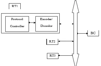
REMOTE TERMINAL MODULE
ARCHITECTURE
In the MIL_STD 1553B Bus Protocol, One terminal works as Remote terminal and the other two terminals one works as a bus controller and other works as bus monitor. Whenever the communication among remote terminal and subsystems are needed RT acts as main source component. RT mainly contains encoding, decoding unit and protocol controller. The RT can be an independent subsystem or it can be part of the subsystem. The Standard allows maximum of up to 31 RTs in a system. Fig 2 illustrates the block diagram architecture for Remote Terminal (RT) module.
Fig.2: Remote Terminal Module Block Diagram
4.
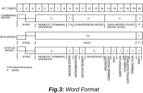
WORD FORMAT
Each word structure is unique and that follows as shown in figure 3. Each word consists of 20 bits, In that word is divided
————————————————
Santhosh Reddy S, MTech Student, [email protected]
Shivaputra, Assistant Professor, [email protected]
Meenakshi L Rathod, Assistant Professor,
Shwetha M, Assistant Professor, [email protected]
Dept. of ECE, Dr. Ambedkar Institute Of Technology,
to 3 parts : sync(3-bits), information(16-bits) and parity bit(1-bit) at the end.
Fig.3: Word Format
RT responds to BC when the Terminal address(first 5 bits)field in the command word matches with terminal address of Remote terminal. Actual information is accommodated in data word and RT sends it’s status by sending status word.
5.
MESSAGE FORMAT
The communication in MIL-STD 1553B happens in 3 different ways. In this receive command is nothing but a BC–RT message transfer command this transfers happens when Bus Controller sends a Command word to all the RTs. The Terminal address of RT is included in Command word. RT sends back status by validating data and command words by forming of status word. Format for BC–RT commuication is shown in figure 4. Transmitting command means bus controller asks RT to send or transmit it’s status with data words as included in the command word. Format for RT-BC commuication is shown in figure.
Fig. 4 : BC-RT Communication Format
Fig. 5 : BC-RT Communication Format
6.
DESIGN AND IMPLEMENTATION
Message transfer process initiate by Bus Controller by passing command word, this command word decides weather the Remote Terminal should receive or transmit or to perform some other tasks. After initiating the message process BC passes data word, this contains the actual information. In this protocol maximum 32 data words one information can contain. Remote Terminals transmit status word to acknowledge the transmission. Protocol controller should perform all the function RT. i.e., status word should be sent after each message transfer which indicating status of RT. All blocks of RT are in verilog HDL. Simulation, synthesis is completed
using Cadence NCSIM and Cadence Genus Tool and final Physical Layout is done Using Cadence Innovus Tool.
I. ENCODER BLOCK
The 20 bit word transmitted in the bus wire contains 16 bits of data to that one bit parity is attached by the encoder and 3 bits of command or date sync. The task of the encoder is converting input data into serial format. In this project the Manchester code encoder is used, it consumes less power and have lot more advantages like error recovery, synchronization etc than any other encoding decoding techniques.
Fig.6: Block Diagram of Manchester Encoder
II. DECODER BLOCK
Decoder reads 20 bit encoded serial data received. It decodes and converts it back to original 16 bit data word. While receiving the data parity check is performed.. Mainly decoder finds whether it is a data word or command word. Figure shows the decoder block diagram.
Fig.7: Block Diagram of Manchester Decoder
III. PROTOCOL CONTROLLER
1492
7.
PROPOSED ALGORITHMS FOR BC-RT AND RT-BC COMMUNICATIONS
1494
8.
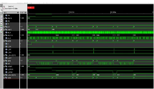
RESULTS AND ANALYSIS
Fig 10 : Simulation Results of BC-RT Communication
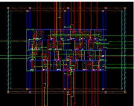
Fig.12: Schematic Diagram of Remote Terminal Module
1496
9.
CONCLUSION
In this paper highly Efficient Remote Terminal module is designed and verified the function of Remote terminal through different message transfer types like BC-RT ,RT-BC. As per the output obtained the delay taken and area utilization are less. And the same remote terminal module is developed using Cadence Innovus Tool for further optimizations and converted to Physical Design layout. As per future scope, as the demand in military, airspace applications increases the demand for efficient and highly reliable protocol standards also increases.so further this developed Remote Terminal Module will be used in upcoming bus communication protocols.
REFERENCES
[1] C. D. NAIDU, P. KISHORE, Y. PADMA SAI, B. SOURAV, ―Design and Implementation of Remote Terminal for MIL-STD1553B‖, 2017 IEEE 7th International Advance Computing Conference. [2] L. Karthik, K.V. Ramana Reddy, Dr. Siva Yellampalli,
―Design and Verification of MIL-STD-1553B Remote Terminal Modules‖. International Journal of Engineering and Technical Research (IJETR) ISSN: 2321-0869, Volume-3, Issue-5, May 2015.
[3] Jemti Jose and Sharone Varghese, ―Design of 1553 protocol controller for reliable data transfer in aircrafts‖, In Proceedings of the 12th International Conference on Intelligent Systems Design and Applications (ISDA 2012), Cochin, India, pp 686-691. [4] Sharon Theresa George, J. Mangaiyarkarasi, "Design
and Implementation of Mil-Std 1553B Bus Protocol Controller with FPGA and ASIC", International Journal of Research in Engineering & Advanced Technology, Volume 3, Issue 3, JuneJuly, 2015.
[5] Siji K, Saritha N, "FPGA Implementation of MILSTD1553B Bus Protocol Controller for Aircrafts", International Journal of Science and Research (IJSR), ISSN (Online): 2319-7064, Volume 4, Issue 7, July 2015.
[6] Jemti Jose, ―Design of manchester || bi-phase encoder for MILSTD-1553 protocol‖, IEEE 12th International Conference on Intelligent Systems Design and Applications, pp 240-245, 2013.
[7] Suchitra Suresh, ―VHDL implementation of manchester encoder and decoder‖, International Journal of Electrical, Electronics and Data Communication, vol.1, issue 2, April 2013.