RESEARCH ARTICLE
MARGIN EFFECT ON CRACK PROPAGATION OF COLD-WORKED HOLE UNDER FATIGUE LOADING
1, *
Toumi, A. and
2Bernard, M.
1
Faculty of Science and Technics UH1, Settat Morocco
2
Department of Mechanical Engineering, École Polytechnique de Montréal, Canada
ARTICLE INFO ABSTRACT
A fatigue test program was carried out with the aim to study the effect of the cold working process on the fatigue crack propagation life. Plate specimens of 7475-T7351 aluminium alloy containing a pre-cracked fastener hole with different edge margins have been subjected to cyclic loading of constant amplitude. During a test, the fatigue crack length was monitored using a video-camera system; the results permitted to establish the evolution of the crack along the bore and across the short ligament of the specimen. Three-dimensional finite element simulation of the cold working process has been conducted for establishing the residual stress field around the fastener hole. The residual stress distribution resulting from the process was then combined with the applied stress for calculating the crack propagation life, taking into account the edge margin effect.
INTRODUCTION
Failure of critical structural components in service is usually originated in the region where the local stress is relatively high due to loading mode as well as to the presence of stress raisers. In order to improve the fatigue strength of a fastener hole plate, the cold working process is usually applied to the hole prior to the fastener installation (Jost, 1992; Champoux, 1986; Rich et
al., 1977; Bernard et al., 1993). This process involves a
split-sleeve cold expansion realized by drawing a tapered mandrel through the fastener hole in order to plastically deform the material adjacent to the hole edge. It has, therefore, the capability to increase the material resistance against cyclic loading due to the characteristics of elastic plastic response of the material under the cold expansion. The fatigue life improvement due to cold working is attributed mainly to the delay in the crack initiation period and to the retardation in the crack growth rate due to the presence of residual stresses. In a study of the cold working effect on crack initiation and crack propagation periods, it is important to establish correctly the residual stress field generated by the cold expansion; this stress field is then combined to the cyclic loading for evaluating the efficiency of the process on fatigue life improvement. This could be done by means of 3-D finite element analysis. In the past, most investigations on the beneficial effect of the cold working process have been carried out using plate specimens with a central hole (Forgues et al., 1993; Burlat, 1994). This paper concerns only the edge margin effect on the fatigue crack propagation characteristics of plate specimens containing a central or an eccentric hole subjected to cold expansion process.
*Corresponding author: Toumi, A.
Faculty of Science and Technics UH1, Settat Morocco
EXPERIMENTAL PROCEDURE
Material and Specimen Configuration: Specimens were
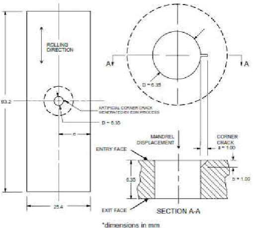
made from a 7475-T7351 aluminium alloy plate of 6.35 mm in thickness with the axis oriented in the rolling direction of the plate. A hole was machined in the central portion of the gauge section, as shown in Fig. 1. The initial hole diameter was determined in order to have a final dimension of D = 6.35 mm after the completion of the cold working process. In addition to the case of central hole (e/D = 2.0 where e is the distance between the hole centre and the specimen edge), two other values of the edge margin parameter were considered (e/D = 1.6 and 1.2). For these specimen geometries, the stress concentration factor (K tg ) at the hole edge ranges from 3.22 (for e/D = 2) to 3.38 (for e/D = 1.2) on the basis of the gross stress (Toumi, 2003).
Cold Working Process: The hole was cold worked in
laboratory using a hand tool with a split sleeve, provided by FTI (Fatigue Technology Inc., Seattle, Wa). The split sleeve of 0.2 mm in thickness was pre- lubricated in order to reduce the pulling force and to protect the hole edge from damage during the expansion process. Cold working was achieved by the interference between the initial hole diameter (d h) and the maximum mandrel diameter (d m), taking into account the split sleeve thickness (t). The degree of cold working (e*) is defined as follows:
e *( % ) = ( d m + 2 t ) − d h × 100 d h (1)
On the basis of the experimental data obtained from previous work (Forgues et al., 1993; Burlat, 1994; Larouche, 1995) a Article History:
Received 22nd March, 2018
Received in revised form 19th April, 2018
Accepted 26th May, 2018 Published online 30th June, 2018
International Journal of Recent Advances in Multidisciplinary Research
Vol. 05, Issue 06, pp. 3913-3917, June, 2018
Keywords:
cold working degree of e* = 4.68 % was considered in the present study.
Static tensile properties of Al 7475-T7351 are as follows: yield strength S Y = 450 MPa, modulus of elasticity E = 67.2 GPa and tangential modulus of plasticity E' = 1.38 GPa for strains up to 4.5 %.
Figure 1. Specimen geometry used for investigating fatigue crack propagation
After cold expansion, the bore was reamed to provide the final specified diameter (D = 2 R = 6.35 mm); then, an artificial corner crack of 1 mm in length was generated, by means of EDM process, on the hole edge of the specimen entry face (see Fig. 1) where the residual tangential stress is relatively low; this point will be discussed later.
Fatigue Testing: The non cold-worked and cold-worked open
hole plate specimens were subjected to cyclic load at room temperature with a sinusoidal waveform of constant amplitude, using a MTS servo- hydraulic machine. The maximum and minimum nominal cyclic stresses (S max and S min ) were determined from the applied load on the basis of the gross specimen section. The cyclic load was in tension with a stress ratio R = 0.05 (R = S min /S max ). The loading frequency was kept constant (5 Hz). During a fatigue test, two video-cameras (with a magnification of a 50X) connected to an image acquisition system were used to monitor the crack length.
EXPERIMENTAL RESULTS
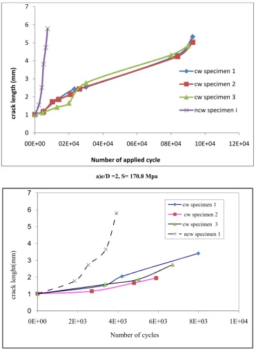
During a fatigue test, it was observed that the crack length extension rate is slightly larger along the bore than across the surface ligament; as a consequence, the triangular shape of the corner crack tends to become a quarter-elliptic form. In this paper, only the data related to the crack extension along the bore will be presented and discussed. Figure 2 shows the crack length plotted in terms of the number of applied cycles for e/D = 2 and 1.2 (two extreme cases) for a given maximum cyclic stress (S max = 170.8 MPa).
a) For specimens containing a non cold-worked hole (NCW), the crack grows with a faster rate for eccentric hole than for a central hole. For example, for extending the crack length from the original value (1 mm) to 3
mm, a number of 2.8×10 3 cycles is required for e/D = 1.2 in comparison to 5×10 3 cycles for e/D = 2.
b) The cold working has definitely a beneficial effect on the retardation of the crack growth. For example, for e/D = 2 (Fig. 2a), the number of cycles required for extending the crack length of a cold-worked hole (CW) to 3 mm is about 8 times that of non cold-worked hole (4×10 4 in comparison to 5×10 3 cycles). For e/D = 1.2 (Fig. 2b), this ratio is slightly smaller (about 2.5). c) As the edge margin parameter decreases from 2 to 1.2,
the crack extension rate in cold-worked hole becomes larger; the number of applied cycles required for extending the crack to a 3-mm length is about7×10^3 for e/D=1.2 in comparison to 4×10 4 for e/D = 2.
Figure 3 shows the experimental results illustrating the edge margin effect on the crack propagation life of a cold-worked hole.
a) For a non cold-worked hole, the margin effect is important and seems to be independent of the applied stress; when the edge margin parameter is reduced from 2 to 1.2, the crack propagation life is reduced by a factor of about 2.
b) The beneficial effect of cold working on the crack propagation life varies, depending upon the edge margin. For e/D = 2, in comparison to the case of non worked hole, the crack propagation life of cold-worked hole is larger for a low stress than for a high stress, by a factor of about 14 at S max = 170.8 MPa and 100 at S max = 137.8 MPa. This factor becomes smaller when the edge margin is reduced, in particular at a high stress level (1.6 at S max = 170.8 MPa for e/D = 1.2).
Finite Element Simulation of Cold Working Process
Finite element model: A three-dimensional model was
considered for simulating the cold working process, using ABAQUS finite element code (ABAQUS User’s manual, 2001). In this analysis, the elastic-plastic behaviour of the split sleeve used in the actual cold working process was ignored and the mandrel was assumed to be an axisymmetric rigid body with an effective diameter equal to its original value increased by twice the sleeve thickness. The meshing model is shown in Fig. 4 for two edge margin parameters (e/D = 2 and 1.6). It is composed of three-dimensional twenty seven nodded quadratic elements with fourteen integration points per element. In the region of high stress gradient (near the hole edge), the mesh was refined. In addition, contact elements were introduced between the mandrel and the plate. For simulating the presence of the lubricated split sleeve, a friction coefficient was also considered with a small value (0.005). The elastic-plastic stress-strain behavior of 7475-T7351 aluminium alloy was modelled with kinematics hardening characteristics. The mandrel was positioned to get in touch with the entry face of the plate and the cold working simulation was then carried out by incrementing the mandrel motion through the hole into 13 steps. For each step, an automatic increment of the mandrel displacement was generated and an iteration procedure in ABAQUS code was performed.
Results from finite element analysis: Since the tangential
a) Figure 5 shows the variation of the residual tangential stress in terms of dimensionless radial position y/R (where y is the distance between the point considered and the hole edge) for three different planes of a specimen with a central cold-worked hole: entry face, exit face and mid-thickness. It is seen that the intensity of the residual stress is relatively less compressive at the entry face. In general, there is a good agreement between the tangential stress distributions and those found with a 2-D axisymmetric model (Poussard and Pavier, 1995; Adler and Dupree, 1974), except for the region very near the hole edge.
b) The residual tangential stress in the vicinity of the hole edge at mid-thickness for three edge margins is essentially the same, as shown in Fig. 6. However, for the smallest edge margin, the core of the compressive residual stress is relatively small and the maximum
tensile residual stress is relatively high in comparison to the two other specimen geometries; this characteristic has an important influence on the crack growth rate, as discussed in the next section.
c) Figure 7 shows the two stress distributions at mid-thickness of the short ligament for each edge margin: the residual stress (already shown in Fig. 6) and the resulting stress obtained from the superposition of the applied stress (stress from the applied load) to the residual stress. The main effect of the residual stress is to reduce substantially the applied mean stress; this would have a direct influence on the crack growth rate of a cold-worked hole.
Fatigue propagation life calculations: Calculations were
performed for determining the fatigue crack propagation life of hole plates by means of AFGROW program (Harter, 2003).
a)e/D =2, S= 170.8 Mpa
b) e/D =1.2, S= 170.8 SMpa
Figure 2. Crack length in terms of the number of applied cycles (S max =170.8 MPa)
00E+00 02E+04 04E+04 06E+04 08E+04 10E+04 12E+04
0 1 2 3 4 5 6 7
Number of applied cycle
cr
ack
length
(m
m
) cw specimen 1
cw specimen 2
cw specimen 3
ncw specimen i
0E+00 2E+03 4E+03 6E+03 8E+03 1E+04
0 1 2 3 4 5 6 7
Number of cycles
cr
ack
leng
ht
(mm
)
cw specimen 1
cw specimen 2
cw specimen 3
Figure 3. Fatigue propagation life of plates having a non cold-worked or a cold-cold-worked hole
Figure 4: Meshing model for finite element analysis b) eccentric hole (e/D = 1.6) a) central hole ( e/D = 2 )
Figure 5. Tangential residual stress field for a central cold-worked hole plate
Figure 6. Tangential residual stress distribution in the short ligament at mid-thickness of a cold worked hole plate
Figure 7. Tangential stress field in the short ligament at mid-thickness of a cold-worked hole plate under S max = 137.8 MPa
Figure 8. Crack propagation in cold-worked hole plates (S max = 170.8 MPa)
The AFGFROW model included the offset of the hole and a specified initial crack length. For this program, the following information should be specified:
a) The quarter-elliptic corner crack configuration; it is required for determining the stress intensity factor (K I ) on the basis of the residual stress on the entry face of the specimen and the applied cyclic stress using the linear superposition approach. The residual stress intensity solution was based upon a Gaussian integration method as the weight function technique was not available for this particular case.
c) The residual stress field due to cold working applied to the hole plate.
d) The applied maximum cyclic stress and the stress ratio applied to the hole plate.
e) Basic data of crack growth of the material; for 7475-T7351 aluminium alloy, the crack propagation rate da/dN (in mm/cycle) in terms of the effective stress intensity factor range ∆K eff (in MPa⋅m 1/2 ) has been reported in (Zhang et al., 1987):
The concept of using ∆K eff has been suggested in order to account for the crack closure effect; this parameter is defined in terms of ∆K I taking into account of stress ratio R = K Imin /K Imax as follows [13]:
The calculated fatigue propagation lives for non cold-worked hole plates are closed to the experimental results, as expected; the calculated lives is on the conservative side, within a factor of about 1.3, as seen in Fig.8. For cold-worked hole plates, the AFGROW program predicts a cold working effect on the fatigue crack growth much larger than that observed in experimental data. In fact, the calculated lives deviate significantly from the experimental results on the non-conservative side, by a factor of about 17 for e/D = 1.2 (Fig. 8b); for e/D = 2, the AFGROW model indicates no crack growth while the experimental fatigue life is finite (Fig. 8a). Similar results on predicted standstill condition of crack emanating from Al 7075-T651 cold-worked holes have also been reported (Kolay et al., 2003). This situation is probably due the combined effects resulting from several sources. First, as the crack front progresses, a relaxation of the residual stress would occur and modify the stress intensity factor. Secondly, secondary cracks which have been observed during fatigue tests would have actually contributed to accelerate the propagation process. These factors have not been considered in the numerical model for fatigue life calculations.
Conclusion
Fatigue tests on non cold-worked and cold-worked hole plates of 7475-T7351 aluminium alloy with different edge margins have been carried out for studying the crack propagation life. a) For a non cold-worked hole plate, the propagation life of the eccentric hole is reduced with respect to the central hole, as expected. When the edge margin decreases from 2 (central hole) to 1.2 (eccentric hole), the propagation life is reduced by a factor of 2, independently of the applied stress. b) The results obtained from a three-dimensional finite element analysis of the cold working process applied to a fastener hole indicate that the effect of edge margin on residual stress distribution is important. A small edge margin reduces the intensity of the residual compressive stress and raises the residual tensile stress. This characteristic would reduce the enhancement of fatigue propagation life associated to the central hole case.
c) Calculations of fatigue propagation life for non cold-worked and cold-worked hole plates have been carried out using AFGROW program. For the first case, the predicted lives are close to the experimental results, on the conservative side. For the second case, however, the deviation of the predicted lives is on the non-conservative side by a factor of about 17 for e/D = 1.2; for e/D = 2, the AFGROW model reported that the crack stayed standstill while the experimental fatigue life was finite.
REFERENCES
ABAQUS User’s manual, version 6.2, Hibbit, Karisson and Sorens Inc. (2001).
Adler, W. F. and Dupree, D. M. 1974. Stress analysis of cold-worked fastener holes, Technical report AFML-TR. Bernard, M., Bui-Quoc, T. Julien, D. and Forgues, S. 1993.
Feasibility study of cold expansion process modelling, École Polytechnique, Project CDT-P907-2967, Report submitted to Canadian Dept of Defence, 243 pages. Burlat, M. 1994. Effet et optimisation de l'écrouissage des
trous des plaques d'assemblage sur le comportement en fatigue, Mémoire M. Sc. A., École Polytechnique de Montréal.
Champoux, R. L. 1986. An overview of cold expansion methods, in Fatigue Prevention and Design, edited by J. T. Barnby, Engg Mat. Advisory Services, pp. 35-52.
Forgues, S., Bernard, M. and Bui-Quoc, T. 1993. 3-D Axisymmetric numerical analysis and experimental study of the fastener cold working processing, Proc. Computer methods and experimental measurements for surface treatment effects, pp. 61-70.
Harter, J. A. 2003. AFGROW User's Guide and Technical Manual, AFRL-VA-WP-TR-XX 2003.
Jost, G. S. 1992. Stresses and strains in plain and coldworked annuli subjected to remote, interference or combined loading, Aerospace Research Laboratory-Structure, Technical Report, 446.
Kolay, M. T., Retis, J. and Reid, L. 2003. Fatigue crack behaviour and interaction with the residual stress field of cold-worked hole, Paper presented at ICAF 2003, 14 p. Larouche, S. 1995. Influence des techniques d'assemblage et
de la géométrie sur la vie en fatigue des joints rivetés, Mémoire M. Sc. A., École Polytechnique de Montréal. Poussard, C. and Pavier, M. J. 1995. Analytical and finite
element predictions of residual stresses in cold worked fastener hole, J. Strain Analysis for Engg Design, pp. 291-304.
Rich, D. L. and Impellizzeri, L. F. 1977. Fatigue analysis of cold-worked and interference fit fasteners holes, ASTM STP 637, pp. 153-175.
Toumi, A. 2003. Étude de l'effet d'écrouissage et de l'excentricité sur le comportement en fatigue des joints rivetés, Mémoire M. Sc. A., École Polytechnique de Montréal.
Zhang, S., Marissen, R., Schulte, K., Trautmann, K. K., Nowack, H. and Schijve, J. 1987. Crack propagation studies on Al 7475 on the basis of constant amplitude and selective amplitude loading histories, Fat. Fract. Engg Mat. Struct., vol. 10, pp. 315-332.