Abstract— Time-Triggered Cooperative (TTC) schedulers
provide simple, low-cost software architecture for many embedded applications which have severe resource constraints and require high degrees of predictability. Basic implementations of TTC scheduler can be achieved using Super Loop (SL). Such implementations, however, lack the provision of high predictability in case where tasks running in the system have unpredictable execution durations or various execution periods. This paper reviews the previously developed TTC-SL scheduler and presents an alternative scheduler implementation called ―Fixed-Tick TTC-SL scheduler‖. The implemented scheduler is evaluated in terms of tick- and task-jitter using a popular family of ARM-based microcontrollers. The results show that such an implementation – although simple – can help to achieve a significant reduction in release jitter at the tick and the ‗top priority‘ task at negligible cost in terms of memory overheads.
Index Terms— super loop, sandwich delay, cyclic executive, time-triggered, cooperative scheduling, tick interval, jitter.
I.INTRODUCTION
The majority of embedded systems run only one software program. This program usually starts to execute when power is applied to the microcontroller and stops executing when the power is removed (or some error occurs) [1]. Moreover, there is no operating system returned to by the program, and allowing the program to terminate might have undesirable consequences. In order to avoid this, a form of endless “Super Loop” (SL) is usually employed [1],[2]. In the example shown in Listing 1, the application has a “one-shot” task to be executed only once and then the program will remain in the super loop doing nothing until the whole system is reset. It is obvious that the super loop is employed mainly to “stop” the system.
M. Nahas is with Umm Al-Qura University, Makkah, Saudi Arabia (phone: +966(2) 5270000; e-mail: [email protected]).
int main(void) {
Do_X(); while(1);
// Should never reach here return 1
}
Listing 1: Use of a “Super Loop” to avoid termination of a simple embedded application.
However, the super loop can be used as the basis for implementing a simple Time-Triggered Cooperative (TTC) scheduler (e.g. [1],[2]). TTC scheduler – which is sometimes referred to as "cyclic executive" [3],[4] – operates as follows: tasks execute in a sequential order defined prior to system activation; the number of tasks is fixed; each task is allocated an execution slot (called a minor cycle or a frame) during which the task executes; the task – once interleaved by the scheduler – can execute until completion without interruption from other tasks; all tasks are periodic and the deadline of each task is equal to its period; the worst-case execution time of all tasks is known; there is no context switching between tasks; and tasks are scheduled in a repetitive cycle called major cycle
[3],[4]. Fig. 1 illustrates the (time-triggered) cyclic executive model for a simple set of four periodic tasks. Note that the final task in the task-group (i.e. Task D) must complete execution before the arrival of the next timer interrupt which launches a new (major) execution cycle.
Provided that an appropriate implementation is used, TTC schedulers can be a good match for a wide range of embedded applications, even those which have hard real-time requirements [3] - [9].
Implementation of Highly-Predictable
time-Triggered Cooperative Scheduler using Simple
Super Loop Architecture
Task B
Task C Task D
Task A
Fig. 1. A time-triggered cyclic executive model for a set of four periodic tasks (adapted from [10]).
A possible implementation of TTC scheduler using super loop is illustrated in Listing 2.
int main(void) {
... while(1) { TaskA(); Delay_6ms(); TaskB(); Delay_6ms(); TaskC(); Delay_6ms(); }
// Should never reach here return 1
}
Listing 2: A very simple TTC scheduler which executes three periodic tasks, in sequence.
By assuming that each task in Listing 2 has a fixed duration of 4 ms, a TTC system with a 5 ms “tick interval” has been created using a combination of super loop and delay functions (Fig. 2).
Time
System Tick
Task A
10 ms
Task B
Task C
4 ms 4 ms 4 ms
Fig. 2. The task executions resulting from the code in Listing 2.
Note that if task durations are variable, then it is almost impossible to achieve a precisely fixed tick interval with this approach, making the use of such a super-loop-based scheduler inappropriate for systems which have rigid timing constraints.
This paper provides one way in which a super loop approach can be used to implement a highly-predictable TTC system with variable task durations. Such an implementation is referred to as Fixed-Tick TTC-SL scheduler.
The remainder of the paper is organized as follows. Section II describes the Fixed-Tick TTC-SL scheduler. Section III outlines the experimental methodology used to evaluate the Fixed-Tick TTC-SL scheduler. Results in terms of time jitter
and implementation costs are presented in Section IV. The overall conclusion is drawn in Section V.
II. FIXED-TICK TTC-SL SCHEDULER
The Fixed-Tick TTC-SL scheduler is based on the use of “Sandwich Delay” [11] that is placed around the tasks. Briefly, a Sandwich Delay (SD) is a mechanism – based on a hardware timer – which can be used to ensure that a particular code section always takes approximately the same period of time to execute. The SD operates as follows:
• A timer is set to run. • An activity is performed.
• The system waits until the timer reaches a pre-determined count value.
In these circumstances – as long as the timer count is set to a duration that exceeds the WCET of the sandwiched activity – SD mechanism has the potential to fix the execution period. Listing 3 shows how the tasks in Fig. 2 can be scheduled – again using a 10 ms tick interval – if their execution durations are not fixed.
int main(void) {
... while(1) {
// Set up a Timer for sandwich delay SANDWICH_DELAY_Start();
// Add Tasks in the first tick interval Task_A();
// Wait for 10 millisecond sandwich delay // Add Tasks in the second tick interval SANDWICH_DELAY_Wait(10);
Task_B();
// Wait for 20 millisecond sandwich delay // Add Tasks in the second tick interval SANDWICH_DELAY_Wait(20);
Task_C();
// Wait for 30 millisecond sandwich delay SANDWICH_DELAY_Wait(30);
}
// Should never reach here return 1
}
Listing 3: A TTC scheduler which executes three periodic tasks with variable durations, in sequence.
Using the code listing shown, the successive function calls will take place at fixed intervals, even if these functions have large variations in their execution durations (Fig. 3).
Time
System Tick
10 ms
Task B Task
C Task A
6 ms 9 ms 4 ms
Fig. 3. The task executions expected from the TTC-SL scheduler code shown in Listing 3.
results of this paper.
III. EXPERIMENTAL METHODOLOGY
A. Hardware platform
The empirical studies reported in this paper were conducted using Ashling LPC2000 evaluation board supporting Philips LPC2106 processor [12]. The LPC2106 is a modern 32-bit microcontroller with an ARM7 core which can run – under control of an on-chip PLL – at frequencies from 12 MHz to 60 MHz [13]. The oscillator frequency used was 12 MHz, and a CPU frequency was 60 MHz.
The compiler used was the GCC ARM 4.1.1 operating in Windows by means of Cygwin (a Linux emulator for windows). The IDE and simulator used was the Keil ARM development kit (v3.12).
B. Jitter test
For meaningful comparison of jitter results, the following two task-sets were used (Fig. 4 and Fig. 5). In task-set #1, all tasks have fixed durations and they are scheduled to run in each tick interval. Task-set #2 was used to allow exploring the impact of schedule-induced jitter by scheduling Task A to run every two ticks. Moreover, all tasks were set to have variable execution durations to allow exploring the impact of task-induced jitter.
B1
Major cycle
A1
B2 A2
C1
t = 0 1
C2
t = 0 1
t (Ticks)
t = 0 1
t (Ticks)
t (Ticks)
Fig. 4. Graphical representation of the task-set #1 in jitter test.
Note that in both task sets, the maximum duration of Task A is 2 ms which is double the duration of Task B and Task C (each with duration equals 1 ms). Also, Task A has the highest priority and Task C has the lowest priority. The tick interval used was 5 ms.
B1 A1
B2
C1
t = 0 1
C2
t = 0 1
t (Ticks)
t = 0 1
Task A
Task B
Task C
t (Ticks)
t (Ticks) Major cycle
B3 A2
C3 2 2 2
Fig. 5. Graphical representation of the task-set #2 in jitter test.
Listing 4 shows how the task-set illustrated in Fig. 5 was implemented in the TTC-SL scheduler.
int main(void) {
... while(1) {
// Add Tasks in the first tick interval TaskA(); // its max duration is 2 ms TaskB(); // its max duration is 1 ms TaskC(); // its max duration is 1 ms
// Wait for 1 millisecond delay to complete the 5 ms tick // interval
Delay_1ms();
// Add Tasks in the second tick interval TaskB();
TaskC();
// Wait for 3 millisecond delay to complete the 5 ms tick // interval
Delay_1ms(); }
// Should never reach here return 1
}
Listing 4: Implementing the TTC-SL scheduler for tasks shown in Fig. 5.
Listing 5 shows how the task-set illustrated in Fig. 5 was implemented in the Fixed-Tick TTC-SL scheduler.
int main(void) {
... while(1) {
// Set up Timer 1 for sandwich delay SANDWICH_DELAY_T1_Start();
// Add Tasks in the first tick interval Task_A();
Task_B(); Task_C();
// Wait for 5 millisecond sandwich delay SANDWICH_DELAY_Wait (5);
// Add Tasks in the second tick interval Task_B();
Task_C();
// Wait for 10 millisecond sandwich delay SANDWICH_DELAY_Wait (10);
}
return 1; // Should never reach here ... }
Listing 5: Implementing the Fixed-Tick TTC-SL scheduler for tasks shown in Fig. 5.
Jitter was measured at the release time of tick and each task. To measure jitter experimentally, we set a pin high at the beginning of the tick or task (for a short time) and then measure the periods between every two successive rising edges (Fig. 6). We recorded 5000 samples in each experiment. The periods were measured using a National Instruments data acquisition card „NI PCI-6035E‟ [14], used in conjunction with appropriate software LabVIEW 7.1 [15].
Time Tick 0 Tick 1 Tick 2 Tick 3
Period 1 Period 2 Period 3
Fig. 6. The technique used to measure release jitter in tick (for example).
obtained from the measurements in the sample set. This jitter is sometimes referred to as “absolute jitter” [16]. The average jitter is represented by the standard deviation in the measure of average periods. Note that there are many other measures that can be used to represent the levels of task jitter, but these measures were felt to be appropriate for this study.
C. CPU test
To obtain CPU overhead measurements in each scheduler, we run the scheduler for 25 seconds and then, using the performance analyzer supported by the Keil simulator, the total time used by the scheduler code was measured. The percentage of the measured CPU time out of the total running time was also reported.
D. Memory test
In this test, CODE and DATA memory values required to implement each scheduler were recorded. Memory values were obtained using the “.map” file created when the source code is compiled. The STACK usage was also measured (as part of the DATA memory overhead) by initially filling the data memory with „DEAD CODE‟ and then reporting the number of memory bytes that had been overwritten after running the scheduler for sufficient period.
IV. RESULTS
A. Jitter
Table I and Table II present the measured release jitter in the tick and all tasks in the TTC-SL and Fixed-Tick TTC-SL schedulers, respectively.
TABLE I
TICK AND TASK JITTER FROM THE TTC- SCHEDULER (ALL VALUES IN µS).
Tick Task A Task B Task C
TTC-SL
Task-set #1
Min Period 4999.6 4999.6 4999.6 4999.6
Max Period 5000.5 5000.5 5000.5 5000.5
Average Period 5000.0 5000.1 5000.0 5000.1
Diff. Jitter 0.9 0.9 0.9 0.9
Avg. Jitter 0.3 0.3 0.3 0.3
TTC-SL
Task-set #2
Min Period 1005.5 4005.5 1005.5 1005.5
Max Period 5000.5 10000.2 7000.5 6000.5
Average Period 3000.5 7002.5 3000.5 3000.5
Diff. Jitter 3995.0 5994.7 5995.0 4995.0
Avg. Jitter 1020 1135 1116 1025
The results in the table show that with the task-set #1, the jitter levels are small and can be accepted. On the other hand, when the task-set #2 is applied (where tasks vary in their durations) the jitter levels at both tick and tasks are very high. This jitter is caused by the variation in task durations and tasks periods. Recall that the scheduler is originally designed to run tasks with fixed and known execution times. Such a jitter behavior is unacceptable in many applications where
deterministic timing is required for predictable operation.
TABLE II
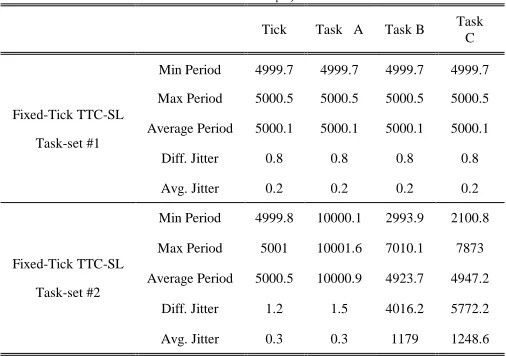
TICK AND TASK JITTER FROM THE FIXED-TICK TTC-SL SCHEDULER (ALL VALUES IN µS).
Tick Task A Task B Task C
Fixed-Tick TTC-SL
Task-set #1
Min Period 4999.7 4999.7 4999.7 4999.7
Max Period 5000.5 5000.5 5000.5 5000.5
Average Period 5000.1 5000.1 5000.1 5000.1
Diff. Jitter 0.8 0.8 0.8 0.8
Avg. Jitter 0.2 0.2 0.2 0.2
Fixed-Tick TTC-SL
Task-set #2
Min Period 4999.8 10000.1 2993.9 2100.8
Max Period 5001 10001.6 7010.1 7873
Average Period 5000.5 10000.9 4923.7 4947.2
Diff. Jitter 1.2 1.5 4016.2 5772.2
Avg. Jitter 0.3 0.3 1179 1248.6
From the results in this table, it can be seen that with the Fixed-Tick TTC-SL scheduler the tick occurs at deterministic timing (with very low levels of release jitter). It is worth noting that obtaining zero jitter in the release time of the tick is difficult, however, the tick jitter can still be very low. Also from the results, when fixing the duration times and periods of tasks (as with the task-set #1) the jitter in the release time of all tasks was maintained very low. This behavior is expected. Moreover, even if all tasks vary in their execution durations and regardless of the frequency (i.e. period) of the running tasks, the "top priority" task (which possesses the highest priority) always runs with low jitter in its release time (as with the task-set #2).
Results also show that when the scheduler major cycle had more than one tick (as in task-set #2) the tick jitter and Task A jitter values have slightly increased. This is due to the variation in time taken to leave the software loop – which is used in the SD mechanism – and begin to execute the tasks in the next tick. In Listing 6, one way of implementing such a SD mechanism is shown.
void SANDWICH_DELAY_ Wait(const unsigned int DELAY_MS) {
// The timer is set so that one count equals to one microsecond
int i = DELAY_MS;
// Wait for Timer 1 count to reach delay while (T1TC < i)
{ ; } }
Listing 6: An example of “sandwich delay” function used in TTC-SL scheduler.
B. CPU and memory requirements
mode [1] when not executing tasks: instead, the scheduler waits in a “while” loop.
TABLE III
CPU OVERHEAD FOR THE TTC-SL AND FIXED-TICK TTC-SL SCHEDULERS.
Scheduler time (s): Total time (s): Overhead %
TTC-SL
Task-set #2
25.00 25.00 100
Fixed-Tick TTC-SL
Task-set #2
25.00 25.00 100
Note that in any super loop scheduler, the CPU uses 100% of the time resources. Such a CPU requirement causes an increase in the overall system power consumption.
The memory required to implement the TTC-SL and Fixed-Tick TTC-SL schedulers are summarized in Table IV for comparison purposes. Note that there is no difference in memory requirements between the task-set #1 and #2. Hence, only task-set #2 was considered.
TABLE IV
MEMORY REQUIREMENTS (ROM AND RAM) FOR THE TTC-SL AND FIXED -TICK TTC-SL SCHEDULERS
ROM requirements
(Bytes)
RAM requirements
(Bytes)
TTC-SL 2150 120
Fixed-Tick TTC-SL
Task-set #1
2264 124
It can be seen from the table that implementing the Fixed-Tick TTC-SL scheduler would only required 5% and 3% increases in code and data memories, respectively. Such memory costs are totally insignificant.
V. CONCLUSIONS
Time-triggered cooperative (TTC) architectures provide a good solution for a wide range of embedded applications where predictability is a key concern and resources are limited. This paper discussed ways for implementing TTC scheduler using simple super loop architecture aimed at matching the requirements for the aforementioned types of real-time embedded applications.
This paper is only concerned with enhancing the performance of simple TTC schedulers based on the use of super loop. The results show that the time accuracy can be enhanced by applying a form of sandwich delay around each tick interval in the super-loop scheduler. The modified scheduler implementation was referred to as Fixed-Tick TTC-SL scheduler. Such a modification – as indicated in the results – required only a slight increase in memory overheads while achieving high timing predictability.
In general, software architectures based on super loop can be seen simple, highly efficient and portable. However, these approaches lack the provision of accurate timing and the efficiency in using the power resources, as the system always
operates at full-power which is not necessary in many applications. An appropriate solution to this problem is to make use of the hardware resources to control the timing and power behavior of the system. For example, a TTC scheduler implementation can be created using “Interrupt Service Routine” (ISR) linked to the overflow of a hardware timer. This approach is beyond the scope of this paper and is discussed in detail in [2].
Further work in this area may include the utilization of ISR approach (and low-power idle mode) along with advanced software techniques to achieve high timing predictability at low power requirements. Examples of some highly-predictable implementations of the TTC algorithm are discussed in [8],[17],[18]. Such implementations, however, require relatively large memory requirements.
ACKNOWLEDGMENT
The work described in this paper was part of a project carried out in the Embedded Systems Laboratory (ESL) at University of Leicester, UK. The author would like to thank Professor Michael Pont for supervising this project.
REFERENCES
[1] M.J. Pont, Patterns for time-triggered embedded systems: Building reliable applications with the 8051 family of microcontrollers, ACM Press / Addison-Wesley, 2001.
[2] S. Kurian, and M.J. Pont, “Maintenance and evolution of resource-constrained embedded systems created using design patterns,” Journal of Systems and Software, vol. 80, No. 1, pp. 32-41, 2007.
[3] T.P. Baker and A. Shaw, "The cyclic executive model and Ada," Real-Time Systems, vol. 1, No. 1, pp. 7 – 25, 1989.
[4] C.D. Locke, "Software architecture for hard real-time applications: cyclic executives vs. fixed priority executives," Real-Time Systems, vol. 4, pp. 37 – 52, 1992.
[5] M.J. Pont and M.P. Banner, "Designing embedded systems using patterns: A case study," Journal of Systems and Software, vol. 71, No, 3, pp. 201 – 213, 2004.
[6] D. Ayavoo, M.J. Pont and S. Parker, "Does a „simulation first‟ approach reduce the effort involved in the development of distributed embedded control systems?," in 6th UKACC International Control Conference, Glasgow, Scotland, 2006.
[7] T. Nghiem, G.J. Pappas, R. Alur, and A. Girard, "Time-triggered implementations of dynamic controllers," in Proceedings of the 6th ACM & IEEE International conference on Embedded software, Seoul, Korea, 2006, pp. 2-11.
[8] T. Phatrapornnant and M.J. Pont, "Reducing jitter in embedded systems employing a time-triggered software architecture and dynamic voltage scaling," IEEE Transactions on Computers, vol. 55, No. 2, pp. 113 – 124, 2006.
[9] M. Short and M.J. Pont, "Fault-Tolerant Time-Triggered Communication Using CAN," IEEE Transactions on Industrial Informatics, vol. 3, No. 2, pp. 13 – 142, 2007.
[10] D. Kalinsky, “Context switch,” Embedded Systems Programming, vol. 14, No. 1, pp. 94 – 105, 2001.
[11] M.J. Pont, S. Kurian and R. Bautista-Quintero, "Meeting real-time constraints using „Sandwich Delays‟," Transactions on Pattern Languages of Programming I, 5770/2009, 2009, Springer Berlin / Heidelberg, pp. 94 – 102, 2010.
[12] LPC2000 Evaluation and Development Kits datasheet, Ashling
Microsystems, 2007. Available:
http://www.ashling.com/pdf_datasheets/DS266-EvKit2000.pdf [13] LPC2106/2105/2104 USER MANUAL, Philips Semiconductors, 2003.
Available:
[14] Low-Cost E Series Multifunc-tion DAQ – 12 or 16-Bit, 200 kS/s, 16 Analog Inputs, National Instruments, 2006. Available:
http://www.ni.com/pdf/products/us/4daqsc202-204_ETC_212-213.pdf
[15] LabVIEW 7.1 Documentation Re-sources, LabVIEW, 2007. Available:
http://digital.ni.com/public.nsf/allkb/06572E936282C0E486256EB000 6B70B4
[16] G. Buttazzo, Hard real-time computing systems: predictable scheduling algorithms and applications, Springer, New York, 2005.
[17] M. Nahas, M.J. Pont and A. Jain, "Reducing task jitter in shared-clock embedded systems using CAN". In: Koelmans, A., Bystrov, A. and Pont, M.J. (Eds.) Proceedings of the UK Embedded Forum 2004 (Bir-mingham, UK, October 2004), Published by University of Newcastle upon Tyne, 2004, pp. 184 – 194.
[18] Z.M. Hughes and M.J. Pont, "Reducing the impact of task overruns in resource-constrained embedded systems in which a time-triggered software architecture is employed", Transactions of the Institute of Measurement and Control, vol. 30, 2008, pp.427 – 450.
Mouaaz Nahas (M‟01) was born in UK on 1977.
He received the B.Sc. degree (Electrical Engineering) from Jordan University of Science and Technology, Jordan, in 2001, the M.Sc. degree
(Communications Engineering) from
![Fig. 1. A time-triggered cyclic executive model for a set of four periodic tasks (adapted from [10])](https://thumb-us.123doks.com/thumbv2/123dok_us/1385475.1649382/2.612.94.256.54.232/fig-triggered-cyclic-executive-model-periodic-tasks-adapted.webp)