ISSN (Online): 2320-9364, ISSN (Print): 2320-9356
www.ijres.org Volume 5 Issue 10 ǁ October. 2017 ǁ PP. 65-69
Study And Calibration on the Intake Flow Control of Multipoint
Injection Gas Engine
Huang Mintao
1,Wu Changshui
2,Feng Chen
3,Wang Zhibin
4(College of Automotive Engineering, Shanghai University of Engineering Science, China)
Corresponding Author:Huang MintaoABSTRACT:
Engine ECU can achieve precise control of the throttle opening through the control strategy,which can precisely control the air flow rate.And the control precision of air flow rate determines the control accuracy of air-fuel ratio in the engine. So, it is vital to the precise calculation of the air flow. After the acquisition of steady state data by the engine testing, this paper calculates the air mass flow according to the flow characteristics of the injector, and then use throttle flow model to calculate and correct it . Finally we could obtain a formula which can accurately calculate the air mass flow of transient and steady state conditions. Using simulink to build the throttle flow model, so as to improve the air-fuel ratio control strategy module.During the calibration of engine ECU, avoid a lot of engine bench test was carried out on the fuel injection pulse-width MAP calibration.It has the vital significance of engine ECU calibration.Keywords :
Airflow;Air-fuel ratio;Gas engine--- Date of Submission: 12-10-2017 Date of acceptance: 27-10-2017 ---
I.
INTRODUCTION
The improvement and optimization of the engine's control strategy is carried out on the basis of the engine bench test, which is very important for the control of the air mass flow. The precise control of the quality of the air entering the cylinder directly affects the control of the air-fuel ratio, which is also an important part of the overall air-fuel ratio control[1]. By precisely controlling the electronic throttle opening to achieve precise control of the air mass flow, the appropriate amount of fuel is supplied according to the target air-fuel ratio. Therefore, selecting a suitable algorithm is critical to the calculation of engine air mass flow. This paper is based on a six-cylinder multi-point EFI gas engine ECU calibration project as the background. It is desirable to obtain a computational model that can accurately calculate the air mass flow to accommodate the control strategy of the multi-point EFI gas engine. Not only reduces the engine ECU calibration workload, but also improve the engine ECU calibration data accuracy.
II.
GET
ACTUAL
AIR
MASS
FLOW
In order to obtain the relevant calculation parameters, a multi-point EFI engine bench test was carried out. Using eddy current dynamometers, CANape online calibration tools, pressure sensors, temperature sensors and oxygen sensors.
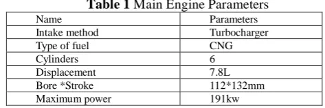
Table 1 Main Engine Parameters
Name Parameters
Intake method Turbocharger
Type of fuel CNG
Cylinders 6
Displacement 7.8L
Bore *Stroke 112*132mm
Maximum power 191kw
And then,we obtained a large number of engine bench test data through the engine bench test.
Table 2 Engine Bench Test Data
Air-fuel ratio
The pressure
before the Throttle Intake air Throttle Injection
Corresponding author.
rpm throttle (bar)
pressure (bar)
temperature (k) opening
%
pulse (ms)
900 20.83 1.04 0.71 315 16 2.7
900 16.56 1.34 1.28 308.2 60 6.5
900 21.88 1.27 1.04 313.5 23 4
1000 17.55 1.40 1.39 319.3 60 2.72
1000 20.36 1.05 0.75 312.6 18 6.48
1000 19.89 1.27 1.07 313 24 4.32
1300 20.83 1.05 0.66 305.4 19 2.3
1300 19.19 1.45 1.22 313.3 27 5.3
1500 20.83 1.06 0.66 320.4 20 2.4
1500 20.13 1.43 1.22 314.5 26 4.7
1700 20.01 1.11 0.76 317.4 24 2.8
1900 20.48 1.55 1.31 317.6 33 5.3
Before the air-fuel ratio control strategy has not been perfected, the engine bench calibration test is given by the man-made injection (gas) pulse width[2]. Since the engine is a six-cylinder multi-point EFI gas engine, six injectors are required to provide fuel for each cylinder. After the engine is converted into a multi-point EFI gas engine, the fuel is controlled by the injector of the control strategy. Therefore, according to the steady-state engine bench test data, according to the CANape interface display parameters, including the nozzle valve flow rate (injector flow characteristics is 16mg / ms), calculated steady state conditions per hour supply of natural gas , According to the air-fuel ratio, and then calculate the hourly air mass flow. The hourly fuel injection is calculated as:
6
3600
120
10
6
w
v
n
Q
Among them:
Q
---Hourly fuel injection (natural gas) mass floww
--Fuel injection pulse widthv
--Injector flow raten
--Engine speedThe fuel mass flow is multiplied by the corresponding air-fuel ratio to obtain air mass flow. The results are as follows:
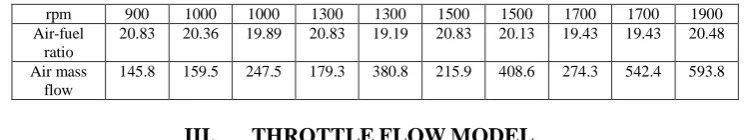
Table 3 Actual air mass flow
rpm 900 1000 1000 1300 1300 1500 1500 1700 1700 1900
Air-fuel ratio
20.83 20.36 19.89 20.83 19.19 20.83 20.13 19.43 19.43 20.48
Air mass flow
145.8 159.5 247.5 179.3 380.8 215.9 408.6 274.3 542.4 593.8
III.
THROTTLE
FLOW
MODEL
The accuracy of the air flow rate of the ignition engine determines the control of the air-fuel ratio. Inaccurate control results in a decrease in engine power and economy, and an increase in harmful emissions[3]. The speed density method can only guarantee the accuracy of the air under steady-state conditions, but in the transient conditions, the use of speed density method will produce a lot of error. So the need to introduce an algorithm to meet the engine under any conditions of air mass flow calculation, and to ensure its accuracy. Using throttle flow model[4]. Consider entering the intake air flow from the throttle passageway. Because the accurate calculation of the air flow through the throttle valve is the need to establish a three-dimensional unsteady flow model, the complexity is too large, which can be simplified as a one-dimensional isentropic stable flow calculation[5], throttle at the channel is also a simple change in the area of the circle The And taking into account the impact of other factors on the formula calculation results. It is desirable to find the relationship between the formula and the true value of the actual intake air volume and then correct it. Making the accuracy of the formula closer to the true value. Theoretically, the air mass flow equation at the throttle is described as:
A
P
C
m
a red thr 1)
cos
1
(
4
2
D
A
redT
R
C
im gk
k
)
1
(
2
153
.
0
,
1
1
)
1
2
(
1 1
P
P
k
thr im kk
k
53
.
0
,
)
(
)
(
1 2
P
P
P
P
P
P
thr im k k k thr im thr im
Where,
D
is the throttle diameter,k is the adiabatic index,R
g is air gas constant,P
im、
P
thr for theintake manifold (after the throttle), before the throttle pressure,
T
im is the intake air temperature.Table 2 in the engine bench test data into the formula, the results are as follows:
Table 4 Theoretical calculation of air mass flow
rpm 900 1000 1000 1300 1300 1500 1500 1700 1700 1900
Air-fuel ratio 20.83 20.36 19.89 20.83 19.19 20.83 20.13 19.43 19.43 20.48
Air mass flow 88.6 111.0 187.9 131.7 276.7 144.5 281.4 208.8 384.4 421.4
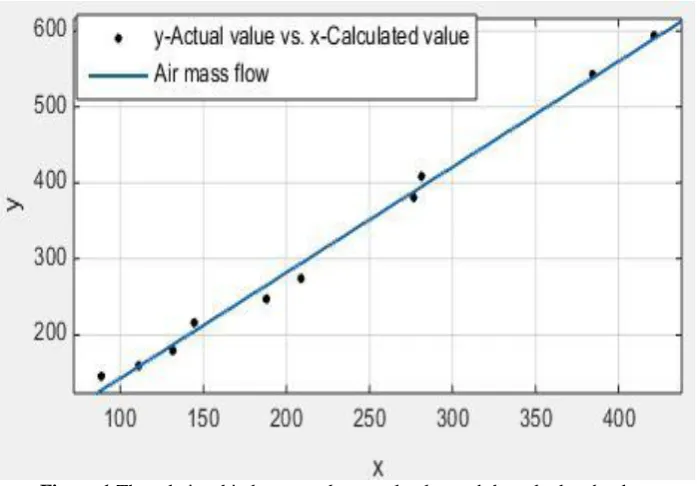
The calculated results of the throttle model and the actual air intake are fitted, and the following relationship exists:
Figure 1 The relationship between the actual value and the calculated value
It can be seen from the figure that there is a linear relationship between the theoretical air mass flow and the actual mass flow. The fitted linear relationship is:
b
m
a
Q
a
Where a and b are constants, according to the correlation analysis, a = 1.389, b = 4.055.So the modified throttle model is expressed as:
055 . 4 389
.
1
ma
Q
IV.
ENGINE
BENCH
TEST
TO
VERIFY
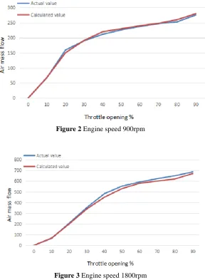
The actual air mass flow rate is compared with the calculated air mass flow rate according to the different throttle opening degrees by the gantry constant rotation torsional mode fixed speed 900rpm and 1800rpm. As shown below:
Figure 2 Engine speed 900rpm
Figure 3 Engine speed 1800rpm
According to the comparison, we can find that the calculated value of the modified formula is close to the actual value, thus verifying the feasibility of the formula..
V.
INFLUENCE OF THROTTLE MODEL ON ECU CALIBRATION
In the absence of a throttle model, the engine ECU calibration is required to perform a large number of engine bench tests to calibrate the MAP of the fuel injection pulse width, not only the workload is large, but also the accuracy of the calibration depends on the fineness of the bench test. Moreover, taking into account the car often run in the transition conditions, when the engine in the transition conditions, if the use of open-loop fuel injection control, the impact of air-fuel ratio is very large, oil and gas matching is difficult to achieve the best. And this also requires a large number of calibration tests for the engine ECU, which will undoubtedly increase the product development costs and cycles.
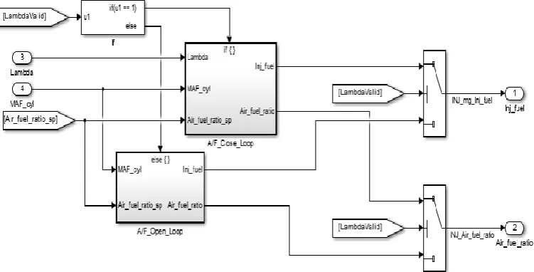
air-fuel ratio approaches the target air-air-fuel ratio, and when the condition is satisfied, the basic air-fuel injection amount under the working condition is obtained.
Figure 4 Control strategy of air - fuel ratio
VI.
CONCLUSION
In the engine control strategy, the air-fuel ratio control is essential, the engine running to a certain situation, the exact air mass flow determines the engine fuel supply. For gas engines, accurate fuel supply can make the engine lean, economical and emissions will be better. This paper provides a reliable method to correct the throttle model and obtain a model that can accurately adapt to the air flow of the engine by combining some of the data under the steady state of the engine bench test. Making the engine both in the transient or steady state can get a good response, which is the engine ECU calibration is of great significance.
REFERENCES
[1]. Zhang Xizheng. Automotive Engine Electronic Control Technology [M]. Beijing:Mechanical Industry Press,2012,P:78-90.
[2]. Chen Renzhe.Hardware and Software Development of Gas Engine Electronic Control System [D]. Beijing: Tsinghua University, 2011.
[3]. Zhou Qinghui. Modern Vehicle Emission Control Technology[M]. Beijing: Peking University Press, 2010.P:56-60.
[4]. Hendricks,E,Chevalier,A,Jensen.M.,etal.Modelling of the intake Mannifold Filling Dynamics[C],SAE paper 960037,1996.02.
[5]. Wu Wangyi. Fluid Dynamics[M]. Beijing: Peking University Press, 1983.P:28-40.