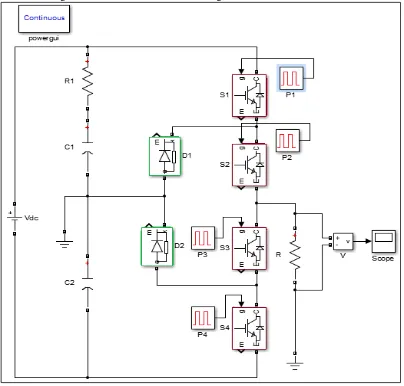
Switching Time Table to Generate Triggering Pulses for a Single Phase Diode Clamped Multilevel Inverter
Full text
Figure


Related documents
International Journal of Scientific Research in Computer Science, Engineering and Information Technology CSEIT1952238 | Received 11 March 2019 | Accepted 27 March 2019 | March April 2019
A thesis submitted in partial fulfillment of the requirements for the degree in Master of Music © Jeff Lupker 2016.. Follow this and additional works at:
In this transformed landscape of public policy, medical evidence, and treatment options, we sought to document patterns and correlates of missed work in a contemporary
We propose a Bayesian statistical method to infer networks of causal relationships among genotypes and phenotypes using expression quantitative trait loci (eQTL) data from
(C) The growth rates of wild-type strain ascospores (GR5, dashed line) and double ⌬ phoA ⌬ phoB mutant ascospores (916, solid line).. (D) Nuclear division in germinating ascospores
[r]
ABSTRACT : An attempt is made to understand difference of dynamic and static earthquake analysis and corresponding shear forces arising in 8 -storied reinforced
