Staying Cable Wires of Fiber Bragg
Grating/Fiber-Reinforced Composite
Jianzhi Li*
Shijiazhuang Tiedao University/Key Laboratory of Structural Health Monitoring and Control, Shijiazhuang, China Email: lijianzhigang@163.com
Yanliang Du and Baochen Sun
Shijiazhuang Tiedao University/Key Laboratory of Structural Health Monitoring and Control, Shijiazhuang, China Email: {sunbch, duyl}@stdu.edu.cn
Abstract—Intelligent hybrid reinforced plastics (IHFRP) with fiber Bragg grating (FBG) sensors embedded in the HFRP were produced in-situ. The FBG/HFRP interface bonding is discussed. Experimental results show that the interfacial bonding of FBG/HFRP is good, which ensures that it can transfer the external load to the FBG sensor well. The novel IHFRP has a higher strain-testing precision compared to the existing products, which is necessary due to the requirements of staying cables. The survival rate of the FBG sensor is high due to the packaged sensor used during the manufacturing process. In addition, a simple and theoretical model to estimate shear and peel-off stress is proposed. According to the simulation results, the maximum shear and peel-off stress are located at the ends of the FBG sensor, and this stress is less than the strength of interfacial adhesion of the matrix material. Moreover, the larger the diameter of the packaged sensor is,the more is the additional stress induced.
Index Terms—hybrid composites, smart materials, structural composites, interface, stress/strain curves
I. INTRODUCTION
Fiber-reinforced plastics (FRPs) have become an ideal future material for staying cables due to their low weight, great strength, corrosion and fatigue resistance, and low coefficient of thermal expansion; these advantages attract scholars and engineers of various countries to study their properties [1–3]. Especially, the railway cable bridge, whose dynamic load and dynamic response are large, needs a cable material with high tensile strength, high elasticity coefficient, and appreciable toughness and damping performance. Research results [4] show that composites with only one type of fiber cannot meet the requirements of mechanical strength and dynamic characteristics. However, with increasing tailoring, hybrid fiber–reinforced plastics (HFRP) attain properties that the individual components do not have. Moreover, HFRP also reduces the cost. Composite cables with high levels of tensile strength, toughness, and damping, in addition to a large elastic modulus, are prepared to meet these demands.
In addition, cable-health monitoring is a key issue. In
*Corresponding author, Tel: 86-311-87936614; Fax: 86-311-87935012
Email address: lijianzhigang@163.com (Jianzhi Li)
recent research, fiber Bragg grating (FBG) has been proven to be the most promising fiber-optic strain sensor due to its elaborate strain-sensing capability [5-9]. Numerous efforts have been undertaken to produce practical FBG strain-gage systems, either mounted on the surface or integrated within the structure. These research experiments provide a reliable guarantee of achieving intelligent functioning of the HFRP cable. For example, tension-monitoring systems based on FBG have huge attraction due to their wavelength-division multiplexing features. Zhang et al. [10–13] have designed an FBG system suitable for real-time, online cable monitoring. However, the FBG sensor in the above-cited studies was mounted on the surface, which reduced the FBG reliability. Therefore, Zhou et al. [14–16] carried out numerous experiments involving the embedding of bare FBGs in FRPs. Nevertheless, the survival rate of FBG is lower without stainless steel package of FBG. In addition, the cable-health monitoring process must possess a higher precision, and the strain errors must be less than a few microstrains. However, the cross-sensitivity of bare FBGs between temperature and strain seriously affect the accuracy of the strain-testing process. Therefore, increasing the test precision of intelligent hybrid fiber reinforced plastics (IHFRP) wires is of utmost importance.
In this study, we manufactured a novel IHFRP wire with a temperature-compensated FBG sensor embedded during the online production of HFRP; moreover, the encapsulation of bare FBG effectively protected the sensors from hostile attack. The novel IHFRP has a higher strain-testing precision compared to the existing products, which is necessary due to the requirements of staying cables. Meanwhile, a simple and theoretical model to estimate shear and peel-off stress is proposed. This study will be an important guide to the further development of IHFRP cables.
II. MODELING AND SIMULATION
stresses. Thus, due to the mismatch of the mechanical properties between the embedded sensor and the host structure, when a load is applied to the structure along the sensor’s longitudinal direction, the lateral mechanical response of the structure may induce further local stress on the embedded FBG sensor and, hence, may induce interfacial debonding. Therefore, refer to Fig. 1, we modeled an anisotropic structure with an embedded FBG sensor, which was developed by our research group [17–19].
A three-dimensional finite element model, with an FBG-sensor angle of 36°, was constructed, as seen in Fig.2. Different values were assigned to the mechanical properties of the structure, while an identical strain was loaded onto the structure along the direction of the embedded FBG sensor, so that the strain evolvement in the HFRP in a vicinity of the embedment can be evaluated along with the changes in the structural property. The structural property parameters are listed in Tab.1, together with those of the FBG sensor.
Figure 1. Concentric cylinder structure model
Figure 2. The 3D finite element model with the angle of 36◦
TABLE I
MECHANICAL PROPERTY OF STRUCTURAL ELEMENTS
EZa(Mpa) tb(mm) PRXZc
FBG sensor 200 0.2/0.25/1/1.5 0.3
IHFRC 200/210/220/245 11 0.28
a EZ represents elastic modulus along z-direction (loading direction) of FBG
sensor and IHFRC.
b t represents the thickness of the cylindrical sensor and diameter of the rod. c PRXZ represents major Poisson’s ratio between x- and z-directions
A. The Influence of Elastic Modulus on Shear Stress According to the numerical simulation result in Fig. 3, the maximum circumferential stress (6.98Mpa) is located at both ends of the sensor, named along L1 the direction,
and less than the adhesive strength between the sensor and epoxy resin (20Mpa). In addition, the shear stress is declining rapidly far away from the sensor end.
From Fig.4, with the modulus increasing of the sensor, the shear stress along L1, L2, and L3 is increasing from
0Mpa to 6.98Mpa. From Fig. 5, the interfacial stress is decreased gradually along the radius of packaged FBG sensor, named along the L2 direction; for example, the
stress located in the core of the FBG sensor is far lower than that of the outer of FBG sensor. From Fig. 6, the interfacial stress is declining rapidly far away from the sensor end, which is identical to the theoretical results. The above simulation results are identical with the theory model.
According to the simulation results, we can conclude that: due to their elastic modulus mismatch between FBG and host structure, embedded sensor did experience additional stress field when load was applied along sensor direction. The more the mismatch exists, the more the additional stress field is induced.
Figure 3. Shear stresses contour(Ecom=245Mpa, D=2mm, d=1.6,
t=0.2mm)
-1 0 1 2 3 4 5 6 7
0 1 2 3 4 5 6
sh
ea
r stre
ss(
×
10
6 )
Distance(×10-4m)
220 210 245 200
Figure 4. Shear stresses on L1 path for different elastic modulus
0.0 5.0x10⁻⁵
1.0x10⁻⁴ 1.5x10⁻⁴ 2.0x10⁻⁴
0.0 0.5 1.0 1.5 2.0 2.5 3.0 3.5 4.0 4.5 5.0 5.5 6.0 6.5
sh
ea
r st
re
ss(
×1
0
6 )
Distance(m)
220 210 245 200
0.00 0.02 0.04 0.06 0.08 0.10 -7
-6 -5 -4 -3 -2 -1 0 1 2 3 4 5 6 7
s
hear
s
tres
s
(
×10
6 Pa)
Distance(m) 220 210 245 200
Figure 6. Shear stresses on L3 path for various elastic modulus
B. The Influence of the Thickness of Packaged Sensor on the Shear Stress
From Fig. 7, we can conclude that: with the thickness increasing of the sensor, the shear stress along L1, L2, and
L3 is increasing from 7.13Mpa to 20.7Mpa. Thus, the
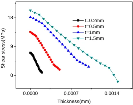
thickness of packaged sensor must be less than 3mm. From Fig. 8, it is shown that the stress is decreased significantly along the radius of FBG sensor, for example, the stress located in the core of the FBG sensor is far lower than that of the outer of FBG sensor. Hence, as long as the thickness of the FBG sensor is less than a certain value, the interfacial debonding between the FBG sensor and HFRP does not induced during the working period of
stayed cable. Therefore, based on the above analysis, the embedded sensor does not affect the mechanical properties of IHFRP.
According to the simulation, we can conclude that: the thickness of packaged sensor must be less than 3mm; the lager the thickness is, the more the additional stress is induced; in addition, the core stress is far lower than the outer stress of FBG sensor.
As we have discussed, according to the safest circumstances the diameter of the designed FBG sensor in this study is 2 mm.
C. Interface Stress Analysis between the Designed Sensor and IHFRP
According to the numerical simulation results shown in Fig. 9, the maximum shear stress (16.6 Mpa) is located at both ends of the sensor and is less than the adhesive strength between the sensor and the epoxy resin (20 Mpa). In addition, the shear stress rapidly declines away from the sensor end. Hence, interfacial debonding between the FBG sensor and the HFRP is not induced during the working period of the staying cable wire.
Fig. 10-12 show the shear-stress curves along the L1, L2,
and L3 paths for three typical cases of different diameters
of the sensor. The interfacial stress is declining rapidly far away from the sensor end, which is identical to the theoretical results in Fig. 10.
Figure 7. Stress contour of sensor model
((a)Ecom=245Mpa,D=3mm,d=2.6,t=0.2mm; (b)Ecom=245Mpa,D=3mm,d=2,t=0.25mm;
0.0000 0.0007 0.0014 0
9 18
S
h
e
a
r str
e
ss(M
P
a)
Thickness(mm) t=0.2mm t=0.5mm t=1mm t=1.5mm
Figure 8. Shear stresses on L3 path for various sensor thicknesses
From Fig. 11, it is shown that the stress is gradually decreased along the radius of the FBG sensor, for example, the stress in the core of the FBG sensor is far lower than that at the outer edges. In the case of a 2-mm diameter sensor, the core stress declines to –1.85Mpa. The maximum shear stress is located at both ends of the sensor (Fig. 10).The maximum shear stress of the FBG sensor with 2-mm diameter is 16.6 Mpa, which is less than the strength of the bond of the sensor with the epoxy
resin (20 Mpa). In addition, the shear stress rapidly declines away from the sensor end. Hence, as long as the diameter of the FBG sensor is less than 2 mm, interfacial debonding between the FBG sensor and HFRP is not induced during the working period of the staying cable. Therefore, based on the above analysis, the embedded sensor does not influence the mechanical properties of IHFRP.
Figure 9 Shear stress contour of sensor model (Ecom=245Mpa)
Figure 10 Shear stress curve on L1 path for composites (Ecom=245Mpa,
D=2mm)
Figure 11 Shear stress curve on L2 path for composites(Ecom=245Mpa,
D=2mm)
Figure 12. Shear stress curve on L3 path for composites(Ecom=245Mpa,
III. EXPERIMENTS AND RESULTS
A. FBG Optical Fiber Sensor Principle and The Other Experimental Materials
FBG is written and formed into a photosensitive optic fiber by modulating the core refractive index periodically using interference pattern created by ultra violet lights through a phase mask. When a broadband light transmits through the optic fiber, the FBG written in the core reflects back a wavelength depending on the Bragg condition:
2
B ne
λ = Λ (1)
Whereneis the effective refractive index of the core andΛis the grating period. The shift in the reflected wavelength of the FBG sensor is approximately linear to any applied strain or temperature. Therefore, the Bragg wavelength shift(ΔλB) caused by the change of strain (Δε) and the change temperature(ΔT) can be expressed as
(
)
(
)
0
0 0
1
B B B
e z f
B B
p T
λ λ λ ε α ξ
λ λ
− Δ
= = − + + Δ (2)
6
7.5 10
f
α + ≈ξ × − (3)
WhereλB0 is the Bragg wavelength at a reference state,pethe strain-optic coeffient of the fiber and ξ is the thermo-optic coefficent of the fiber, respectively.
(
)
2
12 11 12
2
eff
e n
p = ⎡⎣p −ν p +p ⎤⎦ (4)
0.22
e
p ≈ (5)
When the FBG in embedded into a host material and both experience temperature changes, the Bragg equation is modified to account for the thermally induced axial strains in the fiber as a result of the mismatch in the
coefficients of thermal expansion between the optical fiber(αf) and the host material(αm). Therefore, a more generalized equation can be written as
(
)
(
)
(
)
0
0 0
1
B B B
e z m f f
B B
p T T
λ λ λ ε α α α ξ
λ λ
− Δ
= = − + − Δ + + Δ
(6) In the case where the embedded sensor and the host
material are not subjected to any temperature variations, eq. (3) can be futher simplified to the following form:
(
)
0
0 0
1
B B B
e z B B p λ λ λ ε λ λ − Δ
= = − (7)
The Bragg wavelength is also affected by temperature changess. The relative change in the Bragg wavelength due to temperature change is expressed as
(
)
0
0 0
B B B
f B B T λ λ λ α ξ λ λ − Δ
= = + Δ (8)
The FBG used in this study is 10mm long with a reflectivity of more than 90% and bandwidths of 0.2nm. The packaged FBG sensor with temperature-compensated function is made by our team. Therefore, the wavelength is not moved with the temperature change. The FBG sensor used in this study is 2mm diameter and 10mm length.
Moreover, the experimental materials included carbon fiber (Japan Toray production, 6 k, M40J), glass fiber (Nanjing Fiberglass Research and Design Institute, 240Tex), aramid fiber (United States, Kevlar-29), E-618 epoxy resin, methyl tetrahydrophthalic anhydride (curing agent). The material properties is shown in Tab.1
TABLE.II
THE PERFORMANCE PARAMETERS OF VARIOUS FIBER
Fiber Producted Country Strength/Mpa Modulus/Gpa Elongation/% Density/G/cm3 Diameter/
μ
mcarbonfiber Japan 4400 377 1.2 1.77 6
Kevlar-29 America 2800 63 3.6 1.45 12
glassfiber China 4018 83.3 5.7 2.54 10
B. Specimen Fabrication
A cable is a one-dimensional rod suitable for the pultrusion process. The molding temperature was approximately 160 °C. To cure the resin completely, the online curing process was necessary after the molding, and the temperature was about 170~180 °C, which is higher than the glass-transition temperature; The pultrusion speed and molding pressure were, respectively, 0.1 m/min and 0.4–0.5 Mpa. To carry out a thorough investigation on the interface adhesion and the sensing properties of the intelligent HFRP with an embedded FBG strain gauge, two composite specimens were fabricated and studied, as shown in Fig. 13. Furthermore,
to assess and characterize the overall behavior of the embedded FBG sensors, mechanical testing of two pultruded IHFRPs was carried out by applying various loads to the cable wires while continuously monitoring the strain through the embedded FBG sensors and a standard extensometer clipped onto the pultruded rod. In addition, analysis of the interfacial adhesion between the FBG sensor and HFRP was carried out by scanning electron microscopy (SEM).
C. Results and Discussions
stress-sensing experiments show that the sensor can accurately reflect the wavelength changes. The photograph of an entire cross section of the cable is shown in Fig. 14, and the amplified SEM image of the FBG/HFRP interface is shown in Fig. 15. Figures 14 and 16 show that the diameter of the FBG sensor used in this study is approximately 2 mm and that the FBG sensor/HFRP interface bonding is good. Therefore, the interface can transfer the external load to the FBG well; moreover, the FBG sensor is able to accurately reflect the loading environment, which provides a reliable guarantee for achieving intelligent functions of the IHFRP cable wire. Figures 16 and 17 are the stress-sensing curves of two HFRP rods with embedded FBG sensors. The Bragg wavelength of the sensor is linearly dependent on its axial strain, and the strain-sensitivity values of the two
intelligent rods are respectively, 1.35 and 1.4 pm/με
which tallies with the theoretical strain intensity of the FBG sensor and is higher than that of the IHFRP rods in existing products. This also shows that FBG can reflect the external loading environment accurately.
Figure 13. Photo of pultruded intelligent stayed cable wire
Figure 14. Cross-section photo of intelligent wire
Figure 15. SEM of the interface between FBG and HFRP with different amplified times
Figure 16. Strain sensing properties of 1# intelligent HFRP rod
IV. CONCLUSIONS
A simple and theoretical model to estimate both shear and peel-off stress is proposed. The simulation results show: 1) Due to mechanical properties mismatch between FBG and host structure, particularly their elastic modulus, embedded sensor did experience additional stress field when load was applied along sensor direction; and the more the mismatch exists, the more the additional stress field is induced; 2) The interfacial stress is decreased significantly along the radius of FBG sensor for various thickness of packaged; and the larger the thickness is, the more the additional stress field is induced; 3) The maximum shear stress is 16.6 Mpa for the FBG sensor with 2-mm diameter, which is less than the interfacial adhesion strength. Neither fraction nor debonding was observed in this IHFRP rod produced by our team.
In addition, the novel IHFRP produced in this study has a higher strain-test precision and can satisfy the cable-monitoring requirements. Neither fracturing nor interface debonding was observed during specimen fabrication and stress measurements, which proved the survivability of the embedded FBG sensor. The interface between FBG and HFRP is intact, which can transfer the external load to the FBG well and reflects the external mechanical environment accurately. The Bragg wavelength of the packaged sensor is linearly dependent on its axial strain, and the strain-sensitivity values of the two intelligent rods are, respectively, 1.35 and 1.4 pm/με , which tally with the theoretical strain
intensity of an FBG sensor and are higher than those of the intelligent FRP rods found in existing products.
ACKNOWLEDGMENTS
The author would like to thank her collaborators and the financial support of the National Natural Science Foundation of China (50778116), the Natural Science Foundation of Hebei province (E2011210058) and education department in Hebei province.
REFERENCES
[1] Dumlao C, Lauraitis K, Abrahamson E, Hurlbut B, Jacoby M, Miller A,et al.,” Demonstration of low-cost modular
composite highway bridge,” Proceedings of The First
International Conference on Composites in Infrastructure,
Arizona, America, pp. 1141-1145,1996
[2] Taly N, “Design of modern highway bridges,” New York: McGraw Hill, pp.20-25 1998
[3] S. Meiarashi, I. Nishizaki, and T. Kishima, “Life-Cycle Cost
of All-Composite Suspension Bridge,” J. Compos. For
Constr, vol.6, pp.206-213, 2002
[4] Dai De Pei, Engineering applicaton of damping technology, Tsinghua University Press, Beijing, pp.86-88, 1991 [5] Jeannot Frieden, Joël Cugnoni, John Botsis, Thomas Gmür,
“Low energy impact damage monitoring of composites using dynamic strain signals from FBG sensors– Part II:
Damage identification,” Composite Structures, in press.
[6] Jeannot Frieden, Joël Cugnoni, John Botsis, Thomas Gmür, “Low energy impact damage monitoring of composites using dynamic strain signals from FBG sensors – Part I:
Impact detection and localization,” Composite Structures,
in press.
[7] Jeannot Frieden, Joël Cugnoni, John Botsis, Thomas Gmür, “Vibration-based characterization of impact induced delaminating in composite plates using embedded FBG
sensors and numerical modeling,” Composites Part B:
Engineering, Vol. 42,pp. 607-613, June 2011.
[8]Jeannot Frieden, Joël Cugnoni, John Botsis, Thomas Gmür,
Dragan Ćorić, High-speed internal strain measurements in
composite structures under dynamic load using embedded
FBG sensors, Composite Structures, Vol. 92,
pp.1905-1912, July 2010.
[9] Carlos Rodrigues, Carlos Félix, Armindo Lage, Joaquim Figueiras, “Development of a long-term monitoring system based on FBG sensors applied to concrete
bridges, ”Engineering Structures, Vol. 32, pp. 1993-2002,
August 2010.
[10] Zhang, Xushe, Ning, Chenxiao, “Application of fiber bragg
grating sensors on monitoring of cables' tension,”2007 8th
International Conference on Electronic Measurement and Instruments, ICEMI, p 4232-4235, 2007.
[11] Zhang Xu she, Du yan Liang, Jin xiu Mei, SUN Bao Chen,
Journal of Traffic and Transportation Engineering, vol.3,
pp. 22-24, 2003
[12] Zhang Xu she, Du yan Liang and Sun Bao Chen, “Study in Monitoring of Cables Tension with Fiber Bragg
Sensor,”China Safe Science Journal, vol.14, pp.98-100,
2004
[13] Du Yanliang, Shao Lin, Li Jianzhi, Sun Baochen, “Study on the intelligent hybrid composites suitable for stayed
cable,” Journal of Functional
Materials,vol.39,pp.282-286,2008
[14] Zhou Zhi, Zhang Zhichun, Deng Nianchun, Zhao, Xuefeng, Li Dong-sheng, Wang Chuang, Ou Jinping, “Applications
of FRP-OFBG sensors on bridge cables,” Proceedings of
SPIE - The International Society for Optical Engineering, vol.5765, pp.668-677, 2005
[15] Zhou Zhi, Zhou hui, Huang Ying, Ou Jinping, “R and D of smart FRP-OFBG based steel strand and its application in
monitoring of prestressing loss for RC,” Proceedings of
SPIE - The International Society for Optical Engineering,vol. 6933,pp.693313-693316,2008
[16] Fan, Yu Kahrizi, Mojtaba. Characterization of a FBG strain
gage array embedded in composite structure. Sensors and
Actuators A: Physical, vol.21 (2), pp.297-305, 2005
[17] Li Jianzhi, DuYanliang, Liu Chenxi, “FBG strain sensor
based on line forming,” Optics and Precision Engineering,
vol.17 (9), pp. 2069-2075, 2009
[18] Li Jianzhi, DuYanliang, Liu Chenxi, “FBG strain sensor
based on thermal stress mechnism,” Proceedings of the 2nd
International Symposium on Intelligent Information Technology Application, vol.1, pp. 640-642, 2008
[19] Du Yanliang, Li Jianzhi, Liu, Chenxi, “A novel fiber Bragg grating temperature compensated strain sensor,” Proceedings of the 1st International Conference on Intelligent Networks and Intelligent Systems, vol.1,
pp.569-572, 2008
University. Her research interest is strain measurement monitoring system based on FBG (fiber Bragg grating) sensors and intelligent material.
She joined Shijiazhuang Railway University in 2004 after graduating from Fiber Optic Sensing Technology Center, Wuhan University of Technology, undertaking research in novel optical instrumentation, especially in fiber optic sensor development for physical sensing. This work has led into several fields including FBG based strain and temperature sensor systems, intelligent materials, and smart structure. The work has been extensively published in the major journals and
at the international conferences in the field.
Yanliang Du was born in Shenze city
of China on 10 October 1956. He was awarded the degree of doctor in1999, graduating from Beijing University of Aeronautics and Astronautics. His research interest is strain measurement monitoring system based on FBG (fiber Bragg grating) sensors and intelligent materials. Professor Du is currently vice-president of Shijiazhuang Railway University.
Baochen Sun was born in Zhuzhou