Visual Inspection Method for Micro
Tool-Workpiece Contact Detection for Micromilling
Process
Muhammad Syafiq Rahim and Abang Annuar Ehsan
Institute of Microengineering and Nanoelectronics (IMEN),
Universiti Kebangsaan Malaysia,
43600 Bangi, Selangor, Malaysia
One of the issues in the micromilling process is the accuracy of the tool-workpiece settings due to the small cutting tool dimensions. Micron-sized endmill requires a proper detection mechanism for detecting the tool-workpiece contact. In this project, the tool-workpiece contact detection has been achieved using large magnification visual inspection method. Digital microscope with high magnification function is used to detect the contact between micron sized endmill tool with a tool diameter of 200 µm and the workpiece. The effectiveness of the proposed method was verified in a series of experiments conducted using 3-axis computer numerical control (CNC) milling machine. A 700-900x magnification digital microscope was attached to a 3-axes linear stage and positioned in front of the tool-workpiece setting at a working distance of 5 mm to 6 mm. The experimental trials involved the machining with 50 µm in depth on a flat Poly (methyl methacrylate) (PMMA) material. The structure fabricated on the PMMA material using the micromilling process is part of the micro structures for a prototype microfluidics device used for biomedical application. The results from the experiment were analyzed in situ using measurement software. The desired depth of cut is 50 µm and the highest difference depth of cut in the machining using the visual inspection method is 8.31 µm or 16.62 %. The experiment showed some significant and promising results which have improved the accuracy of the machining profiles due to the reduced contact error between the tip of the endmill and the surface of the workpiece.
Keywords: CNC; micromilling; microchannel; microfluidics; micro tools; tool-workpiece contact.
I. INTRODUCTION
Micromilling is one of the methods currently being adopted for microfluidics devices fabrication (Lin et al., 2012). Others micro fabrication technique for microfluidics devices are etching (Bahadorimehr et al., 2010)and 3D printing process (Waheed et al., 2016). Furthermore, a microfluidics channel structure can be in the form of a circular or rectangular microchannel shape cross sectioned (Rahim et al., 2016).
The micromilling process is based on the mechanical technique of selectively removing materials layer-by-layer and can be used to fabricate microfluidics with a rectangular microchannel shape cross section. The parameters for the micromilling operation consist of spindle speed, feed rate, cut of depth and working environments which will affect the final
surface quality of the machined workpiece (Arif et al.,
2010; Arif et al. 2014; Chen et al., 2014; Raja et al., 2014). Figure 1 shows some examples of microfluidic devices fabricated on PMMA, silicon substrates using micromilling process and cross section of a microchannel with a width size of 200 µm and a depth of 50 µm. The area of microchannel for the microfluidic device is vital as microchannel sizes and geometry can affect the focusing width which utilizes hydrodynamic focusing cell (Rahim et al., 2016).
(a) (b) (c)
Figure 1. Microfluidic device on (a) PMMA and (b) silicon (Rahim et al., 2016) with a width size of 200 µm and machined using micromilling process. (c) cross section of a microchannel with a width size of 200 µm and a depth of 50
µm
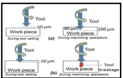
Figure 2. Contact of workpiece and tool during tool setting a) gap between tool and workpiece is 10 µm b) tool goes inside the workpiece by 10 µm (Roy et al., 2016)
The process of micromilling requires that the microtool tip be aligned and positioned on the surface of the workpiece substrate. As shown in Figure 2, a significant gap between the workpiece surface and the tip of the microtool can affect the quality of the machined part such as surface roughness and the actual size of the microchannel. If the gap of tool and workpiece is 10 µm during tool setting, and the desired depth of cut is 100 µm, the actual depth of cut will be 90 µm. On the other hands, as in Figure 2(b), if the tool goes inside the workpiece by 10 µm during tool setting, tool breakage might occur and workpiece might damage (Roy et al., 2016). Hence, there is a need to set an acceptable tool-workpiece contact gap which allows the desired machined part quality to be obtained. Normally, for macro milling process, tool-workpiece contact can be obtained by moving the tool gradually closer to the workpiece and by pinching a piece of paper repeatedly between the tool and workpiece to identify if the contact has occurred. However, this method only suitable in conventional macro machining operation and cannot be used for micromilling operation as the thickness of paper may be greater than 100 µm, hence inaccuracies will occur. From Figure 3, if the thickness of the paper is more than 200 µm, and by using this technique, it is impossible to get the accurate depth of cut of 50 µm.
Figure 3. Tool-workpiece between paper
A recent method for tool-workpiece contact detection method for micromilling is by using accelerometer data which logged into PC where the signals are correlated to detect the tool-workpiece contact (Roy et al., 2016). There are other techniques for tool-workpiece contact detection, such as voltage monitoring and acoustic emission. However, all of this tool-workpiece contact monitoring require additional sensors and due to very small tool dimension, this method requires the use of a high magnification microscope for tool and workpiece contact observation (Broel-plater et al., 2013; Min et al., 2011).
In this study, a simple visual inspection method using a digital microscope is used which allows the tool-workpiece contact detection to be achieved with significant result. Visual inspection is adopted in this project due to its ease of use and low cost and without compromising the quality of the milled surface. The setup comprises of a 700-900x magnification digital microscope attached to a 3-axis precision linear stage and positioned in front of the tool-workpiece setting. The combination micro-movement of the tool and adjusting the position of the linear stage of the microscope allows a microscopic view of the tool-workpiece contact.
II. METHODOLOGY
The tools used in this project composed of a 200 μm
diameter, two flute carbide endmill tool. The tool edge or
cutting radius for the endmill is basically in the range of 9
μm, whereas the rake angle is approximately 4o (Ko TJ et
al., 2005). The CNC milling machine used in this project is
a Mini Mill GX 5-axis desktop CNC machine. The parameter that will be will be investigated is the depth of cut. Table 1,
2 and 3 are the machining parameters of the CNC, tool
parameters and the design parameters respectively. Figure
Paper
PMMA
4 shows the setup for the experiment. As in Figure 4 a) and
Figure 4 b), the tool used is two flute carbide endmill tool with
a diameter of 200 µm, attached to the CNC’s machine spindle.
The digital microscope is positioned in front of the
tool-workpiece setting at a working distance of 5 mm to 6 mm as
shown in this figure.
Table 1. Machine Parameters
Parameters Values
Spindle speed 10,000 rpm
Table 2. Tool Parameters
Parameters Values
Tool Size 0.2 mm
Number of flutes 2
Material of tool Carbide (uncoated)
Table 3. Design Parameters
Parameters Values
Depth
Number of channels
50 µm
10
(a)
(b)
Figure 4. a) Digital microscope, tool setting and workpiece configuration setup b) Diagram of digital
microscope, tool setting, and workpiece setup
(a) (b)
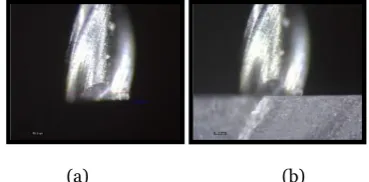
Figure 5. a) Tool inspection b) Tool-workpiece contact
Figure 5 shows a magnified view of the tool used which is
a two flute carbide (uncoated) endmill tool with a diameter
of 200 µm. The workpiece material used is PMMA, and the
digital microscope used, Dino-Lite digital microscope has a
magnification of between 700X to 900X, by using Dino-Lite
measurements tool software, the distance between
tool-workpiece contact can be seen and measured. An
anti-vibration table system is used to absorb anti-vibration that may
occur during machining. In addition, an ultra-clean air
supply unit is used to remove small amounts of burrs and
provide air pressure for cooling the heated spindle head.
The tool-workpiece contact detection process involved the
micro-movement of the tool and adjusting the position of
the microscope via the linear stage manipulator. The digital
microscope is set and focused on the tool or workpiece at a
specific magnification. As the tool is progressed in micro
step towards the workpiece surface, the position of the tool
is determined via measuring the gap between the tip of the
tool and the surface of the workpiece. The process is
repeated until a suitable gap is achieved. In this setup, the
gap is set 20 µm to allows tolerance due to the z-axis tool
setting error prior to the tool-workpiece contact detection.
In this experiment, the milling process is done 10 times,
indicated by channel 1 to 10. The target value for the depth
of cut is 50 µm.
III. RESULTS AND
DISCUSSION
The characterization of the microchannel fabricated using
micromilling process will involve the use of a digital Distance between
digital microscope and workpiece ranging 5 mm –6 mm
Computer Dino Lite Digital Microscope
Measurements Tools
CNC Controller
High Magnification Dino-Lite Digital Microscope
Spindle
Work Piece Tool
microscope. The microchannel for the microfluidic device must
be characterized in order to determine if the design or target
value for the micro channel has been achieved. The depth of cut
will be one of the parameters that must be controlled in order
to achieve the desired design value. The characterization is
done in-situ in which the digital microscope used for contact
detection is also used for measurement. Measurement software
is used to capture and analyzed the viewed image from the
digital microscope. The results for the measured depth of cut
are shown in Table 5.
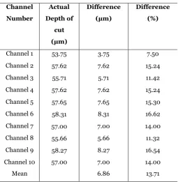
Table 5. The measured depth of cut of the microchannel and
the difference compared with the designed depth of cut by
using a digital microscope during tool-workpiece contact
detection
Channel
Number
Actual
Depth of
cut
(µm)
Difference
(µm)
Difference
(%)
Channel 1 53.75 3.75 7.50
Channel 2 57.62 7.62 15.24
Channel 3 55.71 5.71 11.42
Channel 4 57.62 7.62 15.24
Channel 5 57.65 7.65 15.30
Channel 6 58.31 8.31 16.62
Channel 7 57.00 7.00 14.00
Channel 8 55.66 5.66 11.32
Channel 9 58.27 8.27 16.54
Channel 10 57.00 7.00 14.00
Mean 6.86 13.71
The results shown in Table 5 illustrated that by using visual
inspection technique with a digital microscope, the mean value
for the difference between the actual depth of cut and desired
depth of cut is 6.86 µm or 13.71%. One of the reasons that affect
the accuracy of the measured depth of cut is the interaction
between the tool and workpiece during machining as illustrated
before in Figure 2. Nevertheless, there were no tool breakages
during this experiment. Figure 6 shows the run chart for the
measured depth of cut for the 10 samples as compared to the
designed value.
Figure 6: Run chart for the actual and desired depth of cut
The results shown in Table 5 illustrated that by using
visual inspection technique with a digital microscope, the
mean value for the difference between the actual depth of
cut and desired depth of cut is 6.86 µm or 13.71%. One of
the reasons that affect the accuracy of the measured depth
of cut is the interaction between the tool and workpiece
during machining as illustrated before in Figure 2.
Nevertheless, there were no tool breakages during this
experiment. Figure 6 shows the run chart for the measured
depth of cut for the 10 samples as compared to the designed
value.
IV. CONCLUSION
In this project, a simple and cost-effective real-time
approach is proposed for tool-workpiece contact detection
in micro milling process. The visual inspection method
using a digital microscope enabled a magnified view of the
interface between the tool tip and the workpiece surface.
The measured depth of cut of the channels is measured in-situ using the same digital microscope as used in the visual
inspection. The highest difference depth of cut in the
machining using the visual inspection method is 8.31 µm or
16.62 %. From the run chart, shows that this approach
provides an acceptably stable process in which no
additional device attached to the system is required.
V. ACKNOWLEDGEMENT
The authors would like to thank Universiti Kebangsaan
Malaysia for providing the research funding used in this
project under the UKM grant of GUP-2017-047. Actual
Desired
Channel Depth
Appreciation also goes to all the team members in the Institute
of Microengineering and Nanoelectronics (IMEN), Universiti
Kebangsaan Malaysia.
VI. REFEREENCES
Arif, Muhammad, Rahman, Mustafizur, San, WY &
Doshi, N 2010, ‘An experimental approach to study the
capability of end-milling for microcutting of glass’, The International Journal of Advanced Manufacturing Technology, vol. 53, no. 9–12, pp. 1063–1073.
Arif, Muhammad, Rahman, Mustafizur & San, W Y 2012,
‘An experimental investigation into micro ball end
-milling of silicon’, Journal of Manufacturing Processes,
vol 14, no. 1, pp. 52–61.
Bahadorimehr, AR, Jumril, Y & Majlis, BY 2010, ‘Low
cost fabrication of microfluidic microchannels for
Lab-On-a-Chip applications’, International Conference on
Electronic Devices, Systems and Applications, ICEDSA 2010 - Proceedings, pp. 242–244.
Broel-plater, B, Matuszak, M & Waszczuk, P 2013,
‘Force-measurement based tool-workpiece contact
detection in micromilling’, Pomiary Automatyka
Robotyka.
Chen, PC, Pan, CW, Lee, WC & Li, KM 2014, ‘An
experimental study of micromilling parameters to
manufacture microchannels on a PMMA substrate’,
The International Journal of Advanced
Manufacturing Technology, vol 71, no. 9–12, pp. 1623–1630.
Ko TJ, Rusnaldy, Kim JG, Kim HS 2005, ‘Feasibility study of ductile regime machining of silicon in
micro-end-milling', Proceedings of the First International
Conference on Manufacturing, Machine Design and Tribology. Seoul, Korea: JSME.
Kumar, M, Dotson, K & Melkote, SN 2010, ‘An
experimental technique to detect tool-workpiece
contact in micromilling’, Journal of Manufacturing
Processes, vol. 12, no. 2, pp. 99–105.
Lin, YS, Yang CH, Wang CY, Chang FR, Huang KS &
Hsieh WC 2012, ‘An aluminum microfluidic chip
fabrication using a convenient micromilling process for
fluorescent poly(DL-lactide-co-glycolide)
microparticle generation’, Sensors, vol. 12, no. 2, pp. 1455–1467.
Min, S, Lidde, JR, & Dornfeld, ND 2011, ‘Acoustic
emission based tool contact detection for
ultra-precision machining’, CIRP Annals -
Manufacturing Technology, vol. 60, no. 1, pp. 141–
144.
Muhammad Syafiq Rahim, Norasyikin Selamat, Jumril Yunas & Abang Annuar Ehsan 2016, 'Effect of geometrical shapes on 3D hydrodynamic focusing of a microfluidic flow cytometer', Proceedings of IEEE International Conference on Semiconductor Electronics (ICSE).
Raja Aziz Raja, Catherine, Louis Denis Kevin, Ma’arof
& Sangeeth Suresh 2014, 'Impact of machining parameters on the surface roughness of machined
PU block'. International Journal of Chemical,
Nuclear, Metallurgical and Materials Engineering vol. 8, no. 12, pp. 1370–1375.
Roy, S, Mandal, S & Nagahanumaiah, N 2016, ‘Tool
-workpiece contact detection in micro-milling using
wireless-aided accelerometer sensor’, Proceedings
of the Institution of Mechanical Engineers, Part B: Journal of Engineering Manufacture, vol. 230, no. 1, pp. 182–187.
Norasyikin Selamat, Muhammad Syafiq Rahim, &
Abang Annuar Ehsan 2016, ‘Effect of microchannel
sizes on 3D hydrodynamic focusing of a microflow
cytometer’, Proceedings IEEE International
Conference on Semiconductor Electronics (ICSE), pp. 109–112.