CAD/CAM (Computer Aided Design / Computer Aided Manufacturing) has been utilized in different ways by different people. Some people utilize it to produce drawing and document designs, visual tool by generating shaded images and animated displays, tool path generation, and process planning tools for machining of complex product. This research includes process planning for product manufacturing, machining conditions, and setting the time standards for a product. This research eliminates the demer its of traditional production planning and also improves the quality of a design with the help of CAM tool for CNC programming. It also includes product life cycle management technique which is used for production planning.
Introduction
The materials and manpower costs along with the expenditure required for a company have constantly increased. The requirements of shorter lead time to production have growing research interest in CAD/CAM [1]. For a systematic representatio n of the product is essential to produce a suitable process plan [2]. There has been a goal to reduce these costs by improving the manufacturing process and product design. For improving the process and planning in these days CAD/CAM technology is used. Computer Aided Process Planning (CAPP) is an important part of Computer Integrated Manufacturing (CIM) environment [3]. The process planning in manufacturing involves the coding sequences, selection of machine tools, selection of material for work piece and NC part programs [4].
The CAD interfacing provides the part shape and geometry which is one of the prime forces of the process planning [5]. In these days CAD/CAM development focuses on efficient and fast integration and automation of various elements of design and manufacturing along with the development of new algorithms and technique. In these days various CAD/CAM tools package available for direct usages that are user friendly and very proficient. The new development in CAD/CAM tools are Auto CAD 2014, NX 8, Solid Works 2013 and Creo 3.0.
The Process and operations planning covers many manufacturing processes for making complex shaped products. Suitability of CAD models for manufacturing purposes aims at analyzing the mathematical description of the product shape in relation to the information needed for the automatic process planning. The feature based technology and manufacturing driven geometrical analysis methods belong to the subjects within this research. Research in the field of milling focuses on the evaluation of several multi-axis cutting strategies, Dynamic model segmentation methods, accuracy checks of multi-axis operations v/s 3-axis operations and set-up dependency information retrieval are investigation topics herein.
This research focuses on CAD/CAM & NC programming tools for the design and manufacturing of complex shaped surfaces, tool path generation strategies for multi-axis milling, product design, process planning tools for the machining of complex shapes by multi-axis milling and collision free NC programming through the integration of tool path generation and machine simulation by CIM.
Literature review
Case study
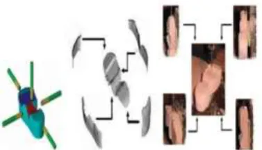
In this research CAPP plays a very special role to reduce cycle time and processing time. It also improves the efficiency of the product and cycle. CAPP enhances the manufacturing process and sequences. In terms of machining processes, the major process planning sequences consist of choosing product design data, selecting machining process, sequencing the operations, determining the proper cutting parameters and tolerance and generating the tool paths and numerical control (NC) data [3]. Traditionally shoe mold making is a very tedious job. By CAD/CAM we generate part design and tool path for shoe mold as shown in Fig 1. Firstly CAD model for shoe mold is generated by plaster casting or Die casting. After that CAD model is machined completely using the three-axis/five sided machining process. The use of five axis machining over three axis machining is only for lower cost and higher efficiency. But from a cost point of view, it is costly, time consuming, and complex.
This research provides an idea for making a complex product manufacturing easier and accurate. For making any complex product the processes are “Creating part design by CAD, Generate a mold for part designed, Generate tool path for NC machining, Finish the product.
Fig 1: Example of Shoe Mold Machining by 5-Axis Milling M/C [3]
Computerized Method
Computer Aided Design and Computer Aided Manufacturing (CAD/CAM) develop much technique for product design and process planning. The Computer Aided Process planning (CAPP) system offers potential for reducing the routine work of a manufacturing engineer. At the same time, it provides the opportunity to generate production routings which are rational, consistent, and perhaps even optimal than traditional.
Tools which required for optimization
The tools which required for product designing are Auto CAD, Pro-E, CATIA, Solid Works, etc. DFMA, DELCAM, PLM and ANSYS are used for optimizing the cycle time and accuracy.
The above mentioned software is used in this research paper for selection of material, product design, and NC tool path generation.
Methodology
Now these days information technology enhances productivity and creates new opportunities for the manufacturing environment. Powerful tools which are used for these planning and design are CAD/CAM/CAPP
The CAPP helps us to reduce the time for manufacturing simplify product design, simple process plan and flexibility in the process [6].
CAD Customization tailors the platform of custom product design to ensure the design consistency and shorter design time. CAPP Customization optimizes the machining parameters ensuring the efficiency and quality of the manufacturing processes.
The product design and selection of design based on the market demand and survey. The product designed with CAD software like CATIA, Pro-E, and UG. The design part checks the aesthetic look and process capability of the product. The designing of complex product and its process planning is a tough task.
The product descriptions geometry, dimensions, tolerances and surface finish with surface treatment. So that for a product, process planning a product should be represented as components which has features plus technological requirements [7].
Fig 3: Vacuum Cleaner Body Casing Lower Half
Fig 4: Vacuum Cleaner Body Casing Assembly Deign
The Figure 2, 3, and 4 shows the CAD model of vacuum cleaner body casing
After product designing the vacuum cleaner body casing is selected based on the complexity for process planning & NC tool path generation. The design selection focuses on product requirements, cost, and quality.
Analysis and selection of material using dfma
Cost breakdown bar chart
The graph in Fig 5 showing the comparison of three materials for cost breakdown. The three materials are Poly Propylene, Nylo n, and PMMA.
Fig 5: Cost Breakdown Bar Chart for Different Materials
Cost vs. life volume
Fig 6: Cost vs. Life Volume Graph for Different Materials Cost reduction
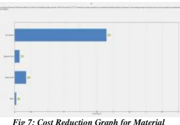
The graph in Fig 7 shows the cost reduction for Poly Propylene material. The graph is generated by DFMA software.
Fig 7: Cost Reduction Graph for Material
Material selection
The material selection is based on the various characteristic like “Good strain resistance, Good insulator, Flame resistance, Low haze, etc. Poly Propylene is cheapest polymer available in the market. Due to this cost of the product is also less as compared to “Poly Carbonate, Nylon, and PMMA”. PP material has also some limitation like melting point up to 2300C, tensile strength up to 3400 psi, etc. The Table I provides the material properties details.
Table1.Material Properties
Material Properties Of Material
Properties Values
Poly Propylene
(PP) Specific Gravity
1-3 kg/m3
Tensile Strength 3400 psi
Operating Temperature -40 to 1150C
Hardness 90 “R”Scale
Melting Point 220-230 0C
Mold Shrinkage 1-3%
Impact Strength 123
Refractive Index 1.49-1.50
Fig 8: Two Plate Injection Mold
Number of impression
The impression depends on the size of the product and the type of mold. Number of impressions mean more volume of product. But more impressions cause more complexity and wastage of material. The more impressions also affect molten plastic flow rate. As preferred “Two Plate Mold” for molding the product. So most preferable design is “Two Impressions”.
Selection of plate material
The selection of mold plate material is based on the nature of work. The core and cavity plate require more finish. The guide pillar and guide bush require more hard. According to all nature and load of work most preferred plate material data are as given in table II:
Table II. Mold Plate Material
Mold Plate
Properties of Material
Mold Material Compositi
on Hardness
Core & Cavity Insert EN30 B
C, Cr, Mn,
Ni, Si 60 HRC
Guide Pillar & Bush EN24
C, Cr, Mn,
Ni, Si 60-62 HRC
Sprue Bush & Knock Out Rod EN18
C, Cr, Mn,
Si 55 HRC
Mold Supprot Plate EN 2A Mn, Si 61 HRC Ejector Pin & Return
Pins Silver Steel
C, Cr, Mo 64-66 HRC
After material selection, heat treatment process is required for improving the mechanical properties of the plate.\
Core/cavity design and nc tool path
Core and Cavity Design
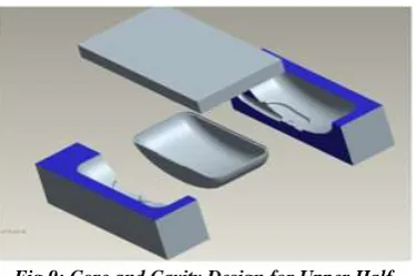
The core and cavity are designed for upper half of the body with the help of CAD tools (fig 9). The upper half has one protrusion on the surface for that generates a split core.
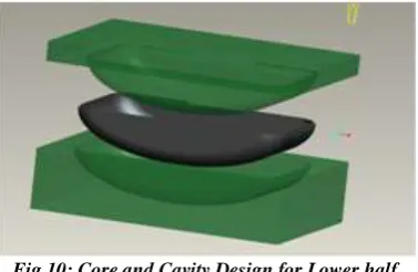
Fig 10: Core and Cavity Design for Lower half
The above Figure 10 shows the core and a cavity half design for the bottom half. The core and cavity are extracted by CAD packages.
NC tool path generation
The NC tool path is generated for all the core and cavity half of the body. The generation of NC programming provides manufacturing possibility of the product. The NC programming reduces the manufacturing time and cost of the product for large volume production. The NC programming is generated by CAM tool and operated by CNC machine.
Conclusion
In this research paper all the data regarding designing, process planning and material selection have been validated with the help of a CAD / CAM tool. The CAD/CAM tool optimizes the time for designing and process planning. The DFMA tool analyzes the lesser cost and high quality product based on the Machine and volume of product manufactured
References
1. Ramanujam Raman and Michael Marefat (2003).”Integrated process planning using tool/process capabilities and heuristic search”. The Journal of Intelligent Manufacturing Vol.15. pp141-174, 2003.
2. M. Kalta and B. J. Davies (1994). “Product representation for an expert process planning system for rotational components”. The Journal of Advance Manufacturing Technology 1994/9. pp 180-187
3. Hsin-Chuan Chen, Hong-Tzong Yau, and Chien-Chung Lin (2011). “Computer-aided process planning for NC tool path generation of complex shoe molds”. The Journal Advance Tool Manufacturing 10.1007/S00170-011-3398-Z.
4. R. L. Sakal and J. G. Chow (1994). “An integrated intelligent process planning system for prismatic parts using PC –based CAD and CAM software packages”. The Journal of Int J Adv Manufacturing Technology 1994 9. pp 166-174
5. Sanjay Joshi and Tien Chien Chang (1990). “Feature extraction and feature based design approaches in the development of design interface for process planning”. The Journal of Intelligent Manufacturing 1990-1. pp 1-15
6. Mikell P. Groover and Emory W. Zimmers, Jr. “CAD/CAM (Computer Aided Design/Computer Aided Manufacturing)”, Low price edition. 2006. pp 320-345.