COUPLING CHARACTERISTICS OF
NON-STANDARD RECTANGULAR
WAVEGUIDE H-PLANE TEE
JUNCTION
M.SUNIL PRAKASH
Professor, Department of Electronics and Communication Engineering,
Maharaj Vijayaram Gajapathi Raj College of Engineering, Vizianagaram, Andhra Pradesh, India [email protected]
Dr. G.S.N. RAJU
Professor, Department of Electronics and Communication Engineering, and
Principal, College of Engineering, Andhra University, Visakhapatnam, Andhra Pradesh, India [email protected]
Abstract:
The analysis of H-Plane Tee junction containing standard rectangular waveguides is extensively reported. In these junctions, coupling takes place through a rectangular slot from primary to secondary guide. Moreover, such structures cannot accommodate the slots of required dimensions due to the fixed dimension of waveguides. In order to have flexibility in the design, non-standard waveguides are proposed for the fabrication of H-plane Tee junctions. Variational method is used for the analysis. The variation of coupling in dB as a function of frequency and slot width are computed. Coupling is evaluated from the equivalent network parameter. The data presented in this paper is extremely useful as there exists sufficient flexibility for the junction designer.
Keywords: H-Plane Tee, Rectangular Waveguide, Non-standard Waveguide, Slot, Coupling
1. Introduction
A narrow slot cut in the wall of a rectangular waveguide is an useful radiating element in highly directive radar antennas and flush mounted antennas. The radiated power in a specified direction is controlled by the slot parameter, dimension of the wave guide and geometry of the slot including its location, feed network and exciting function. Slots cut in the narrow wall should be inclined at least by a small angle from the vertical axis as the vertical slot does not radiate. Earlier papers dealing with both resonant and non resonant slots used equivalent circuits for shunt and series slots which were constructed by employing a standing wave formulation of the wave guide modes [1].
The waveguide junctions are used to split waves from one waveguide into other waveguides. In order to make a three-port waveguide junction it is possible to connect a third arm in a waveguide. The waveguide can be added across the long dimension of the waveguide or across the narrow dimension of the waveguide. The later connection yields a H-plane Tee. An H-plane Tee is electrical equivalent of connecting the arm in parallel or in shunt. In this junction, the circulating magnetic field traveling down in arm 3 meets the junction between arm 1 and 2 and splits the power between the two arms if, as is common, they are of same length. The resulting H-field has the same phase and magnitude in each arm.
In the paper reported by Hanyang et al. [3] the same method is adopted for the analysis of similar Tee junction but the effect of wall thickness is not presented. Oliner et al. [4] reported the analysis of multiport rectangular waveguide devices using pulsed finite-difference time domain technique. A H-plane geometry is considered and the results for the scattering parameters are obtained. Pandharipande et al. [5] obtained the equivalent circuits of a narrow wall waveguide slot coupler and impedance characteristics are presented.
Elliot [6] has done good work on the design of longitudinal shunt slot arrays for resonant and non resonant spacings. Watson [7] derived a relation between the variation in amplitude and slot conductance. The equivalent circuit parameter determination from polarizabilities of the aperture using Bethe’s [8] formulation based on asymptotic representation by dipole moments is limited to smaller slots. This theory has been extended to long slots by Cohn [9]. The internal Green’s functions used to analyze the scattering of a longitudinal slot excited by an incident TE10 were obtained by Stevenson [10].Marcuvitz et al [11] has presented the representation of electric and magnetic fields produced by currents and discontinuities of waveguides. The analysis of electromagnetic energy through the common broad wall between two rectangular waveguides using variational method was reported by Sangster [12].A variational analysis for calculating the admittance of the inclined slots in the narrow wall of a rectangular wave guide was presented by Chen-Gen Jan et al [13].The scattering properties of longitudinal slots using moment method were analyzed by Khac [14].
The analysis of radiating slots in a thick wall rectangular waveguide using moment method was obtained by Lyon and Sangster [15].The characterization of slots in rectangular waveguide by method of moments with proper edge condition was analyzed by Park [16]. Josefsson [17] studied the resonant length of a broad wall longitudinal slot using an accurate method of moment analysis.
No data is available on coupling as a function of frequency and slot width for non-standard waveguide junctions. In view of this, in the present work on H-plane Tee junction the variations of coupling are presented as a function of slot width and frequency for the standard X-band and non-standard waveguide junctions.
2. Formulation
The H-Plane Tee junction of Fig.1 is considered to obtain the formulation for coupling.
Assume the electric field as sinusoidal and it is replaced by its equivalent magnetic current for the junction analysis. The admittance loading is evaluated from the concept of self reaction of the magnetic current with the magnetic field in the coupled guide. Modal voltages Vmn of TE mode and Vmn of TM mode [18] are given by
a
Narrow wall of feed guide
φ
Ψ
φ1
ξ1 Ψ1
W
b
Coupled slot
Secondary Guide Port 1
Port 2
Port 3
L
ξ
a
Fig.2
Fig. 1
Yo
jB Feed Port
Port 1
Yo Port 2 p
− −=
W/2 W/2 L/2 L/2 ' ' e mn slot emn
.
d
ξ
d
ψ
V
E
e
− −=
W/2 W/2 L/2 L/2 ' ' m mn slot mmn
.
d
ξ
d
ψ
V
E
e
(1)The modal voltage in the coupled guide is given by
s 2 2 e 10 slot e 10 E b π L π 2b πL cos L π 4W ab 2 da . V − =
=
E e (2)where ee10 is the dominant mode vector function.
If Vs represents modal voltage of the dominant mode, it is given by [18]
s Es
2 WL
V = (3)
Let Ys represent admittance at the interface of the two guides and Y represent admittance at the primary guide. The relation between Ys and Y is given by
Y = YsN22 (4)
where N2 is no of turns of the transformer
Above expression is valid if the slot coupled junction is replaced by equivalent network consisting of a transformer. The slot admittance is represented by
[
]
e 10 e 10 m n m o m mn e o e mn s V . V y V y V Y 2 2
+= (5)
and the electric field in the slot is given by
< < − < < − = 2 W ξ 2 W 0 2 L φ 2 L L πφ cos E E ' ' ' s
slot (6)
It is well known that the reaction on both sides of the slot interface is considered. Using this concept [18] we have 1 ' 2 10 s 10 s Y I I. Y . V .
V = − (7)
Here I is the discontinuity in modal current [11] and is given by φ)da cosβ j φ sinβ ( E Y
I slot 01 01 z01 01
slot
01 a × • h + h
=
n (8) = 0 01 01 ωμ β Y 2 2 01 b π β β − =
The admittance loading at the primary of the transformer is 2 1 ' 2 1 N Y
Y = (9)
where N1 is no of turns of the transformer and is expressed as
( )
(
)
( )
' 2 2 s s 2 2 n 1 Y . V . V da 1 N
× ⋅ = r E a (10)Using the analysis carried out by Oliner [4] and B N Das et al [2] the imaginary part of the admittance is given by
( )
( )
( ) 2 2 n 2 o ' ' ' ' slot n n dφ dξ Y dφ dξ dφ dξ φ , ξ . .j φ ξ, jX ⋅ × × × =
r E a E a B E a (11)B
j
is expressed using the formulation reported by Marcuvitz [11](
2) ( )
'r r, K
ωμ
j
jB= I+∇∇ •G (12)
where K is the wave number and I is the unit dyadic given by I=aξaξ +aψaψ +aϕaϕ
Using the expression for G(r,r') from Markov[19] and Harrington[18],
)] b nππ cos b nππ cos b nππ sin b nππ sin ( a mππ cos a mππ cos b mππ cos b mππ cos a mππ sin a mππ sin |].[ φ φ | γ exp[ 2abγ ε ε ) r (r, ' φ φ ' ψ ψ ' ' ' ξ ξ ' mn
m n mn
n m a a a a a a G + + − − = ′
(13)expression for jX is simplified in the following form [2]
( )
+ − + + + − − ∈ ∈ = −
2 2 2 2 2 2 2 2 2 L γ 2 2 2 o1 2 o1 2 o1 2 o m n 2 n m L π γ γL L π k L π γ 2 L cosh γ L 2π e γ k 2 L β cos β L π L 2π W bβ π ab 2 y 2a nππ 2a sin 2 nπ cos W 2 ωμ j jX W n ab π γ (14)The normalized admittance loading between p and pl is given by
2 Y Y S T T 11 +
= ,S12 =1+S11 and S33
(
)
(
o I)
I o Y Y Y Y + − = T T Z 1
The admittance loading is used to find out scattering parameters. That is,
Here 's
s 2
1 o
' os
s ' os 2 1
o
2 2 ' os
I jB
t
tanhγ
N 2 Z jX Y
t
tanhγ
Y N
2 Z jX
N Y
Y +
+ +
+
= (16)
and jB's is the imaginary part of ' s
Y
S13 is obtained from the equations which satisfy the unitary property of scattering matrix S*.S=U
Here S* is complex conjugate of S.
(17) An expression for coupling is obtained as
Coupling (dB) = 10 log |S13|2 (18)
3. Results
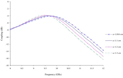
From the analysis presented in the preceding section the following computations are made. 1. Variation of coupling with frequency for different dimensions of narrow wall i.e. a=1.016, 1.1, 1.2, 1.3 cm.
2. Variation of coupling with frequency for different dimensions of broad wall i.e. b=2.286, 2.1, 2.2, 2.4 cm.
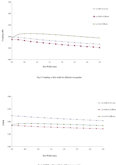
3. Variation of coupling with slot width for a=1.016, b=2.1cm; a=1.016, b=2.286cm & a=1.4, b=2.286 cm. 4. Variation of VSWR with slot width for a=1.016, b=2.1cm; a=1.016, b=2.286cm & a=1.4, b=2.286 cm. 5. Variation of coupling with frequency for a=1.016, b=2.1cm for different slot lengths i.e.
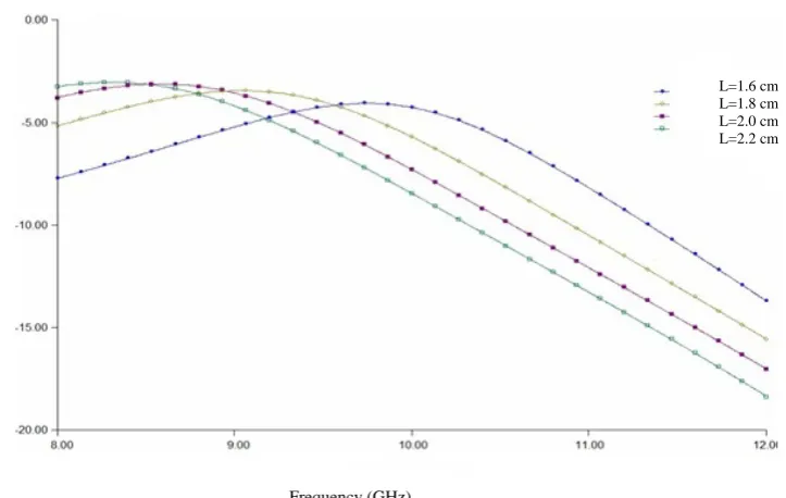
L=1.6, 1.8, 2.0, 2.2 cm.
6. Variation of coupling with frequency for a=1.016, b=2.286 cm for different slot lengths i.e. L=1.6, 1.8, 2.0, 2.2 cm.
7. Variation of coupling with frequency for a=1.4, b=2.286 cm for different slot lengths i.e. L=1.6, 1.8, 2.0, 2.2 cm.
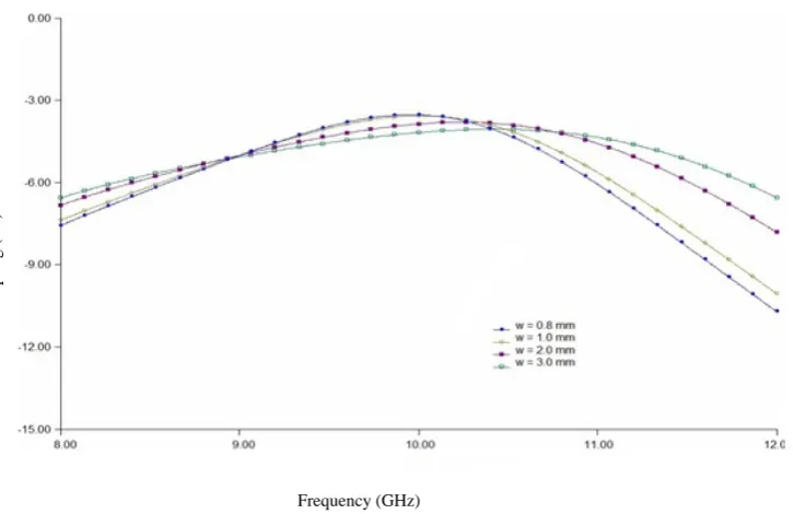
8. Variation of coupling with frequency for a=1.016, b=2.1 cm for different slot widths i.e. W=0.8, 1.0, 2.0, 3.0 mm.
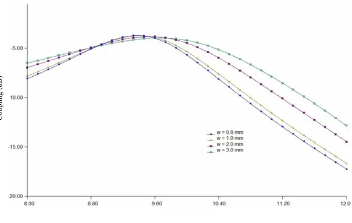
9. Variation of coupling with frequency for a=1.016, b=2.286 cm for different slot widths i.e. W=0.8, 1.0, 2.0, 3.0 mm.
10. Variation of coupling with frequency for a=1.4, b=2.286 cm for different slot widths i.e. W=0.8, 1.0, 2.0, 3.0 mm.
And the above results are presented in figures 3 to 12 respectively.
(
)
2 213
2 4 | |
+ =
T T
-18 -16 -14 -12 -10 -8 -6 -4 -2 0
8 8.5 9 9.5 10 10.5 11 11.5 12
a=1.016 cm
a=1.1 cm
a=1.2 cm
a=1.3 cm
Fig3: Coupling vs Frequency for different waveguides varying narrowwall dimension
-18 -16 -14 -12 -10 -8 -6 -4 -2 0
8 8.5 9 9.5 10 10.5 11 11.5 12
b=2.286 cm
b=2.1 cm
b=2.2 cm b=2.4 cm
Fig 4: Coupling vs Frequency for different waveguides varying broadwall dimension Frequency (GHz)
Frequency (GHz)
Couplin
g (
d
B)
Couplin
g (
d
-6.00 -5.00 -4.00 -3.00 -2.00 -1.00
0.2 0.6 1.0 1.4 1.8 2.2 2.6 3.0
a=1.016 , b=2.1 cm
a=1.016, b=2.286 cm
a=1.4, b=2.286 cm
Fig 5: Coupling vs Slot width for different waveguides
1.00 1.50 2.00 2.50 3.00
0.2 0.6 1.0 1.4 1.8 2.2 2.6 3.0
a=1.016, b=2.1 cm
a=1.016, b=2.286 cm
a=1.4, b=2.286 cm
Fig 6: VSWR vs Slot width for different waveguides Slot Width (mm)
Slot Width (mm)
Couplin
g (
d
B)
VSW
Fig 7: Coupling vs Frequency for non-standard waveguide with a=1.016 cm and b=2.1 cm for different slot lengths
Fig 8: Coupling vs Frequency for standard waveguide with a=1.016 cm and b=2.286 cm for different slot lengths
L=1.6 cm L=1.8 cm L=2.0 cm L=2.2 cm L=1.6 cm L=1.8 cm L=2.0 cm L=2.2 cm
Frequency (GHz)
Couplin
g (
d
B)
Couplin
g (
d
B)
Fig 9: Coupling vs Frequency for non-standard waveguide with a=1.4 cm and b=2.286 cm for different slot lengths
Fig 10: Coupling vs Frequency for non-standard waveguide with a=1.016 cm and b=2.1 cm for different slot widths
L=1.6 cm L=1.8 cm L=2.0 cm L=2.2 cm
Couplin
g (
d
B)
Couplin
g (
d
B)
Frequency (GHz)
Fig 11: Coupling vs Frequency for standard waveguide with a=1.016 cm and b=2.286 cm for different slot widths
Fig 12: Coupling vs Frequency for non-standard waveguide with a=1.4 cm and b=2.286 cm for different slot widths
Couplin
g (
d
B)
Couplin
g (
d
B)
Frequency (GHz)
4. Conclusions
It is evident from the results of coupling that, it varies between -4dB and -16dB over an X-band frequency range. Coupling is approximately the same for waveguides of different narrow wall dimensions, and above the centre frequency coupling is found to depend on the narrow wall dimension. Similarly is the case with different broad wall dimensions. When the h-plane tee junction is made of standard X-band waveguides, the coupling is found to vary between -4.3dB and -4.8dB.When the tee junction is made with non-standard wave guides it has been possible to enhance the coupling. At the same time when the length of the slot is varied from 1.6 to 2.2cms the coupling is found to vary between -4dB and -18dB and it varied between -3dB and -18dB when the width of the slot is varied from 0.8 to 3.0mm.VSWR is found to be dependant on the waveguide dimensions and marginally on slot width. The data presented in the present work is extremely useful for the design of array of h- plane tee junctions.
Acknowledgements
I, M.Sunil Prakash, thank Maharaj Vijayaram Gajapathi Raj College of Engineering, Vizianagaram for the support for my Ph.D work. I also thank Department of Electronics and Communication Engineering, College of Engineering, Andhra University, Visakhapatnam for providing all facilities to pursue my Ph.D work.
References
[1] G.S.N.Raju. Antennas and Wave Propagation. Pearson Education, 2005.
[2] B.N. Das, N.V.S. Narasimha Sarma and A. Chakraborty. “A rigorous variational formulation of an H-plane slot-coupled tee junction”.
IEEE Transactions on Microwave Theory and Techniques, 1990, vol. 38, No. 3, pp. 93-95.
[3] W.Hanyang and W. Wei. “Moment method analysis of a feeding system in slotted-waveguide antenna”. Proc. Inst. Elec. Eng., pt. H, No. 5, pp. 313-318, Oct. 1988.
[4] A.A.Oliner, “The impedance properties of narrow radiating slots in the broad face of rectangular wave guides: part I&II –Theory”, I R E Trans. Antennas Propagat., pp 4-20, Jan, 1957
[5] V.M. Pandharipande and B.N. Das. “Equivalent circuit of a narrow-wall waveguide slot coupler”. IEEE Transactions on Microwave Theory and Techniques, September 1979, vol. MTT-27, No. 9. pp. 800-805.
[6] Robert S. Elliot, “An Improved design procedure for small arrays of shunt slots”, IEEE Transactions on Antennas and propagation, AP-31, No.1, January 1983.
[7] W.H.Watson, “Resonant Slots”,Proc.Inst.Elec.Eng.,part III-A, Vol.93, pp.747-777, 1946.
[8] H.A.Bethe, “Theory of Diffraction By small holes”, Physics Revision, Vol.66, pp.163-182, October 1944. [9] Seymour B.Cohn, “Microwave Coupling by Large Apertures”, Proc.IRE, VOL.40, pp.697-699, 1952.
[10] A.F.Stevenson, “Theory of slots in Rectangular Wave guides”, Journal of Applied Physics, Vol.19,January, 1948, pp.24-38. [11] N. Marcuvitz and J. Schwinger. “On the representation of electric and magnetic fields produced by the currents and discontinuities in
waveguides”. J. Appl. Phys., June 1951, vol. 22, no. 6, pp. 806-819.
[12] A.J.Sangster, “Variational Method for the analysis of waveguide coupling”, Proc.IEE, Vol. 112, No. 12, December 1965, pp. 2171-2179.
[13] Cheng-Geng Jan, Ruey-Beei Wu, and Powen Hsu, “Variational Analysis of Inclined Slots in the Narrow Wall of a Rectangular Waveguide”, IEEE Transactions on Antennas and Propagation, Vol. 42, No. 10, October 1994, pp.1455-1458.
[14] Vu Khac Thong, “Solutions for some waveguide discontinuities by the method of moments”, IEEE Transactions on Microwave Theory and Techniques, June 1972, pp. 416-418.
[15] R.W.Lyon, A.J.Sangster, “Efficient moment method analysis of radiating slots in a thick-walled rectangular waveguide”, IEE Proc., Vol. 128, Pt.H, No. 4, August 1981, pp. 197-205.
[16] Pyong K.Park, George J.Sternn, Robert S.Elliott, “An improved Technique for the Evaluation of Transverse Slot Discontinuities in Rectangular Waveguide” IEEE Transactions on Antennas and Propagation, Vol. 31, No. 1, January 1983, pp.148-154
[17] Lars G.Josefsson, “Analysis of Longitudinal Slots in Rectangular Waveguides”, IEEE Transactions on Antennas and Propagation
Vol., AP-35, No. 12, December 1987, pp. 1351-1357.