TESTING WEB BASED APPLICATIONS
USING FINITE STATE MACHINES
EMPLOYING GENETIC ALGORITHM
Kulvinder Singh
Faculty of Computer Science & Engineering, University Institute of Engineering & Technology,, Kurukshetra University, Kurukshetra-136118 Haryana India
Rakesh Kumar
Faculty of Computer Science & Applications, Department of Computer Application,
Kurukshetra University, Kurukshetra-136118 Haryana India.. Iqbal Kaur
Faculty of Mathematics, Department of Mathematics,
Government Post Graduate College Sec-14 Karnal Haryana India. Abstract
The World Wide Web has become global communication system for delivering information and services. In addition, Web applications becoming more extensive, larger, more interactive, and more essential to the international use of computers. The technological evolution, however, is not supported by adequate Web testing methodologies. Web testing is usually carried out without following a well-defined process and lacks suitable tool support. Since the Web applications, are highly dependable, and as a ground, researcher just now beginning to understand how to model and test Web applications. The Web provides a new mechanism to set up software and there are a number of differences between Web application use and traditional methods. Web applications are installed across a network and they can reveal unusual flows of control. This research addresses external testing issues related to the unique user-level operation and software design structure for web testing. In this paper researcher modeled the web applications into Finite State Machines and then apply the Genetic Algorithm for generating the test cases for testing.
Keywords: Web application; Finite state machines; Genetic Algorithm, Unique Input-output.
1. Introduction
WWW stands for World Wide Web, and it is an advanced information retrieval system. Currently it is mostly in an experimental stage, but it is being developed rapidly. WWW supports information like pictures, graphs, colors, and fonts, if the user's device supports them. Voice can also be delivered, if the user's device has a sound generator [1].
The basis of the WWW is hypertext, which means, among other things, that when the user is navigating on the information he can pick up an interesting word or expression within a text and request for more information about it. This never be applied to all words in a text but only to those which are properly designated as such by the producer of the information and which are displayed on screen e.g. as underlined [1]. In practice, the use of WWW is still largely similar to the use of simpler, menu-driven information systems.
Web site is a collection of Web pages and linked software components which are associated semantically by content and syntactically through links and other control systems. Web sites may be dynamic and interactive. A Web application is a program that runs in whole or in part on one or more Web servers which is run by users through a Web site.
Finite state machines (FSMs) provide a convenient way to model software behavior. Several methods has been proposed for deriving tests from FSMs. Theoretically, Web applications can be completely modeled with FSMs as the web pages have the data, if data is there then this have the states and if states are there, they easily represented using the FSMs. However, there may be large possible inputs to text fields, a large number of options on some Web pages, and choices as to the order in which information can be entered. Factors such as these mean that a finite state machine can become prohibitively large, even for a single page. Thus, an FSM-based testing method can only be used if techniques are found to generate FSMs that are descriptive enough to yield effective tests yet small enough to be practically useful [2].
2. Web Application Structure
The Web Application architecture involves organizing information and navigation mechanisms so that users may find and use that information effectively. The purpose of this workflow detail is to organize the Website’s content and features into a logical structure of the whole Website, define page structures for individual pages or page types (i.e., templates), and to develop navigation mechanisms to facilitate users’ access to information and functionality. The information architecture consists of two major objects: Site Map and Wireframes. Developing information architecture involves organizing information structure and navigation mechanisms so users can find and use that information effectively. The Site Map categorizes all the pages in a Website or Web-based application to show the big picture of the overall structure. Wireframes complement the Site Map. A wireframe is an abstract diagram illustrating the structural aspects of a page or page template. A wireframe defines the types of information and services (including navigation) available on a page. Colors, imagery, shapes, and other graphic design elements are generally addressed in the development of creative approach activities. Therefore, through close collaboration among roles and the use of a controlled set of complementary Site Map and Wireframes and other possible artifacts, the team specifies the functional requirements and information architecture in an optimal fashion [3][4]. So, the process of an effective information architecture should involves the following aspects of design: (i) Clarify site’s mission and vision, (ii) Determine content and functionality, (iii) Map out how the site will change and grow, and (iv) Specify how users will find information by defining: Organization, Navigation, Labeling, and Searching systems[9].
2.1. Organizational Structures
Organization structure presented various ways in which user can search the information. The organizational structures can be classified in various ways: (i) Linear: one after another, (ii) Hierarchy: top-down, (iii) Hypertext: any piece of information can be linked to any other, (iv) Database: information can be brought out as needed, and (v) Programmatic structures: used to provide a look more like that of a computer application than a document
2.2. Linear Structure
It is the simplest structure, which involves only links to a “next” page, or possibly a previous one. Due to this reason, it has limited applications on the Web. Example of linear structure includes slide shows.
2.3. Hierarchical Structure
Resources are deleted from the Web server according to the bin number. If, every n day, one HTML page or PDF file is deleted from bin b. Then, at any given day d during the experiment (where d = 0 is the starting day and d ≤ T), the total number of resources in the Website is defined as: -
The total number of HTML, PDF and image files in bin b on any day d is defined as: Totalb(b ,d) = HTML(b ,d)+PDF(b, d)+ JPEG(b, d)+MPEG(b, d)+IMG(b, d)
The total number of resources in each update bin decreases with the update bin’s periodicity[9]. The total number of resources in each update bin decreases with the bin’s periodicity. The number of HTML, PDF and image files in each bin b on any day d is defined as: -
HTML (b, d) = [T/b] − [d/b] +1
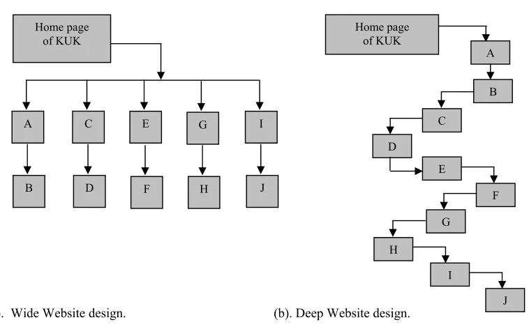
It has been observed that the search engines “prefer” sites that are wide rather than deep, and that having a site index will result in more thorough crawling by the big three crawlers – Google, Yahoo!, and Lycos. Simply put, the resources on a wide Website are found near root level, and have very few “slashes” in the URL:
http://www.kukinfo.com/dirI/X.html, for example. The resources on a deep Website occur in many levels below root and will have several slashes in the URL:
http://www.kukinfo.com/dirA/dirB/dirC/dirD/dirE/dirF/dirG/dirH/dirI/X.html, e.g.: -
(a). Wide Website design. (b). Deep Website design.
Figure 1 (a) and (b) shows wide and deep Websites.
A wide Website has a large number of directories and resources listed at or near root level, i.e., there are only a few “slashes” in the URL. Slashes are an indication of depth in a Website [6][9]. Figure 8.1 (a) is wide, and its 20 resources (A to J) will each only have one or two slashes. For example, the URL for J.html in figure 8.1 (a)
would be http://www.kukinfo.com/dirI/J.html. A deep Website has many slashes in its URLs. The following:
http://www.kukinfo.com/dirA/dirB/dirC/dirD/dirE/dirF /dirG/dirH/dirI/J.htmlis theURL for J.html in figure 8.1
(b), which has 10 slashes, i.e., it is very deep. 2.4. Distributed or Hypertext Structure
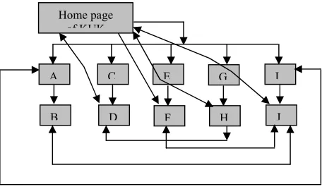
It allows any piece of information to be linked to any other. This provides great flexibility to the designer, but this leads to uncertainty for both the designer and the user. As an organizational standard, the best way to use distributed structure is to add it to a simpler structure such as a hierarchy etc., in the form of links that take the user to all the important pages on the Website. It is good for less structured, creative relationships.
Home page of KUK
A C E G I
B D F H J
Home page of KUK
A
B
C
D
E
F
G
H
I
Figure 2 shows hypertext structure of Website.
2.5. Database Structure
It is a collection of information, which has been divided into records. The records consist of fields, and each field has the same kind of information. The advantages of database in Web-based application is to store online information, which can be repurposed easily, used in different contexts (Web, printed, etc.), and every field has a different way to organize the records[3][4][9]. The disadvantages of database contain: records must follow rigid rules, entire content of a Web page cannot easily be put into a database, and database information must be merged into a Web page template. In Web based applications, the relational database records are grouped into tables and each database table is linked to others by key fields. In order to implement databases in Web-based applications, the static HTML pages can be produced once and put on a server, dynamic Web pages can be produced “on the fly”, static Web pages can be indexed by Web search engines, and dynamic pages can’t be indexed by search engines, and are sometimes called the dark matter of the Web.
2.6. Programmatic Structure
Advanced Web features, such as XML and Extended Style Sheets, can be used to provide some exciting features to a particular Web document. Semantic Web based applications using NeOn toolkit can be used for effective searching, and some other programming languages, such as Java, can be used to provide an interface similar to a computer game[3][4]. JPEG and MPEG media standards can be used to offer a 3D interface with animation, sound, and live video. An example is the Java based Internet railway reservation system, or Internet banking system etc.
3. Modeling Web Applications
Major headings should be typeset in boldface with the first letter of important words capitalized. For testing Web-based application, the Internet Banking System (IBS) of State Bank of India is considered which helps to manage data associated with the customers by offering Personnel Banking, Corporate Banking, and SBI F.A.S.T. as shown in the figure 3. IBS supports several services for each user. Customers first go through a login screen, where they enter a username and password to see personal data related to their account. The services that IBS provides to their customers in Personnel Banking are listed in Table.
Home page of KUK
A C E G I
Figure3: Presents the IB System of SBI
Table1 depicts the services provided by IBS of SBI for personnel banking.
3.1. Modeling Web Applications as FSMs
The modeling of the Web applications as FSMs proceeds in two parts. Part 1 builds a model of the Web application, which further includes four steps: (1) the Web application is partitioned into small modules, (2) My
Account
Payment/ Transfer
Bill Payment
Request Enquiries Profile
e-Tax DEMAT/
ASBA
Account Summery Account Statement Loyalty Points
Fund transfer Third Party Transfer Interbank transfer Demand Draft Status enquiry
Manage Bills
eTDR / e-STDR
Find Transactions
Personnel Details Define limits Manage beneficiary
Enable high Security
Change password Manage Account Display
State Govt Tax
IPO Service only ASBA Add/
modify/ view/ delete/ approve
logical Web pages (LWP) are defined, (3) FSMs are built for each module, and (4) an Application FSM is built to represent the entire Web application. Part 2 generates tests based on the model defined in Part 1 using different methods.
Many Web pages contain more than one HTML form, some of which can be connected to a different back-end software module. To facilitate testing of these modules, Web pages are modeled as Logical Web Pages (LWP). An LWP is either an entire physical Web page or the portion of a Web page that accepts data from the user through an HTML form and then sends the data to a specific software module. The back-end software that processes the form data is declared in the Form Action attribute and client-side software are referred to in individual Form input fields. So if using any hierarchical decomposition, the tester must consider different types of information at different levels of abstraction. However, it is possible that design documentation will already exist that can be used to support this activity, but for now researcher assume the decomposition is the tester’s job and leave the use of pre-existing documentation to future research [2]. The number of decomposition levels may be large or small which depends on the size and complexity of the Web application.
The first step in decomposition will be to partition the Web application into modules. At the highest level, modules should be abstractions that implement functions that can be identified by users. At lower levels, modules should be cohesive software modules and Web pages that collectively work together to implement a portion of a user level function. At the bottom level, modules may be individual Web pages and software modules that represent single major functions themselves. Moreover, modules can be identified from the site navigation layout, coupling relationships among the components, and design information [2].
After a Web application has been partitioned into modules, the next step is to derive a Finite State Machine (FSM) for each module. First, FSMs are generated from the bottom-level clusters that only contain software modules and Web pages. Next, aggregate FSMs are constructed for high-level clusters, in which each FSM from constituent clusters is represented by a single state. Finally, an Application Finite State Machine (AFSM) will define a finite state model of the entire Web application. The FSM of few modules of IBS of SBI is as shown below.
4. Finite-state machine:
A finite state machine [7] is a Six-tuple (X, Y, Q, qo, S, O), where
X is a finite set of input symbols also known as the input alphabet.
Y is a finite set of output symbols also known as the Output alphabet.
Q is a finite set of states.
qoЕQ is the initial state.
S: Q ×X →Q is a next state or state transition function.
O: Q × X → Y is an output function.
Enable High Security Demand
Draft
Select A/C SelectA/C Third party
Back My A/C Home Home Status Enquiry Interbank transfer Fu nd Trans fer Th ir d pa rt y Tr a nsfer Payment /transfer Ba ck R (Username, Password) Personnel Banking
Home Corporate banking
SBI F.A.S.T.
Login MyAccount
Reset Balance Page Ba la nce Payment /transfer Third party
Transfer
Payment option
TP A/C
Submit
In some cases of FSM, more than one state could be specified as an initial state. In addition, sometimes it is convenient to add F Q as a set of final or accepting states while specifying an FSM. The definition of the
transition function S implies that for any state q in Q, there is at most one next state. Such FSMs are also known
as deterministic FSMs. In this chapter, the Nondeterministic FSMs are also concerned. The state transition function for nondeterministic FSMs is defined as which implies that such an FSM can have more than one possible transition out of a state on the same symbol. Nondeterministic FSMs are usually abbreviated as NFSM or NDFSM or simply as NFA for nondeterministic finite automata.
One of the major features of programming is that liquidation of logic in the event handlers and forming of system of interacting automata, which are called from these handlers, causes logic centralization. Automata in this type of system can interact by nesting, by calling ability and with the help of state numbers interchange. Another important feature of state based approach is that automata in it are used for specification, implementation and for drawing up the procedure, which is performed in terms of automata that allows to verify the propriety of FSMs functioning. This procedure could also be used for large-scale tasks and for task with difficult, smeared software logic.
4.1. Unique Input / Output (UIO) Method
However, the number of tests generated using the W-method is usually large. Several alternative methods have been proposed that generate fewer test cases. In addition, these methods are either as effective or nearly as ef-fective as the W-method in their fault-detection capability [7]. A method for test-generation based on unique
input/output sequences is presented in this section. The UIO-method generates tests from an FSM representation
of the design. All the assumptions in this methods are similar to the W method. In addition, it is assumed that the IUT has the same number of states as the FSM that specifies the corresponding design.
A UIO sequence is a sequence of input and output pairs that distinguishes a state of an FSM from the remaining states. Consider FSM M = (X; Y, Q, qo, , 0). A UIO sequence of length k for some state S єQ, is denoted as
UIO(s) and looks like the following sequence:
(s, in(UIO(s))) ≠ (t, in(UIO(s))), t є Q, t ≠ s. 4.1.1. Generation Of UIO Sequences
The UIO sequences are crucial to the UIO-sequence method for generating tests from a given FSM. An algorithm for generating VIO sequences for all states of a given FSM is as follows [MAT 2008]. Procedure for generating UIO sequences
Input: (a) An FSM M = (X; Y, Q, qo, ,O). Where IQI = n.
(b) State s є Q.
Output: UIO[s] contains a UIO sequence for state s; UIO(s) is empty if no such sequence exists.
/* Set(l) denotes the set of all edges with label I. label( e) denotes the label of edge e. A label is of the kind a/b, where a є X and b є Y head ( e) and tail ( e) denote, respectively, the head and tail states of edge e. */
step 1 for each distinct sdge label el in FSM, compute Set(el). Step 2 Compute the set Oedges(s) of all outgoing edges for state s. NE =| Oedges|·
Step 3 For 1≤ i ≤ N E and each edge eiє Out Edges, comp Oled [ij, Opattern [i], and Oend [i] as follows:
Oled [i] = Set (label (ei)) - {ei} Opattern [i] = label(i) Oend [i] = tail (i)
Step 4 Apply algorithm gen-l-uio(s) to determine if UIO[s] consists of only one label.
Step 5 If simple UIO sequence found then return UIO[s] and terminate this algorithm, otherwise proceed to the next step.
Step 6 Apply the gen-long-uio (s) procedure to generate longer UIO
Step 7 If longer UIO sequence found then return UIO[s] and terminate this algorithm, else return with an empty UIO[s]
End of Procedure gen-uio
5. Derivation of Finite State Machine (FSM)
node in a higher level FSM that models behavior of modules. Edges in both levels of FSMs are explained with inputs and constraints that may be associated with the transition.
The Inputs to the FSMs can be of a variety of types, including text (from single digits to single lines to large files), buttons (from single button to choices from a set of buttons), links, etc. Table shows a list of the types of inputs found in Web applications.
Text Non-Text Digit Line Email Phone URL Multiline file Links Buttons Radio buttons Dropdown list Check boxes
Table 2 shows the type of Inputs to the FSMs 6. Web Testing using FSMs
6.1. Representation of Web into FSMs
The banking system divided into small modules. The top level is divided in to three subsystems, which are Personnel banking, corporate banking, and SBI F.S.A.T. which are further divided into modules and WebPages. Table shows the partitioning of physical and logical Web pages for the Personnel banking.
Node Modules Details
SS PB CB SF Select Service Personnel banking corporate banking SBI F.S.A.T.
Menu of main Services
View Personnel banking Services View corporate banking Services View SBI F.S.A.T. Services
Table 3 Shows the Services by SBI Internet Banking.
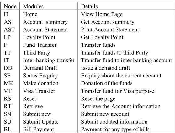
Moreover, the table shows the nodes and the logical web pages related to the personnel banking system .
Node Modules Details
H AS AST LP F TT IT DD SE MK VT RS RT SN SU BL Home
Account summery Account Statement Loyalty Point Fund Transfer Third Party Inter-banking transfer Demand Draft Status Enquiry Make donation Visa Transfer Reset Retrieve Submit new Submit Update Bill Payment
View Home Page Get Account summery Print Account Statement Get Loyalty Point Transfer funds
Transfer funds to third Party
Transfer fund to inter banking account Issue a demand draft
Enquiry about the current account Donation of the funds
Transfer fund for Visa purpose Reset the page
Retrieve the Account information Submit new account
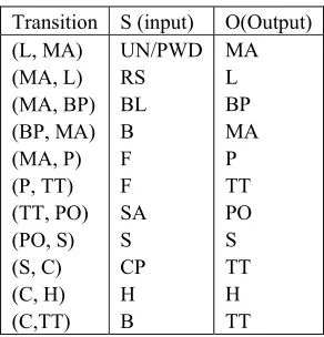
Transition S (input) O(Output) (L, MA)
(MA, L) (MA, BP) (BP, MA) (MA, P) (P, TT) (TT, PO) (PO, S) (S, C) (C, H) (C,TT)
UN/PWD RS BL B F F SA S CP H B
MA L BP MA P TT PO S TT H TT
Table 5 Annotations for Third Party fund Transfer in Internet Banking system of SBI.
6.2. Selecting Inputs
The test sequences for selecting inputs for FSMs define test requirements by encoding the critical design and test criteria decisions[2]. The selection of test value for a sequence T1 is based on random selection. Let Ti be a
test sequence. It contains state identifiers for module FSMs, and AFSM annotations. Processing of testing sequence from the beginning, skipping states, and processing constraints based on following four types:
Required inputs: selects inputs from valid values, subject to relationships in the database and restrictions due to active annotations that can require a particular value be propagated or exclude that value from consideration. Selection can be random, with or without replacement, or driven by other considerations such as small, medium, or large values, or value partitions.
Optional inputs: Randomly select which of the optional inputs are to be assigned values, then select valid values for them as above.
Single choice of input: Randomly select a choice with or without replacement. A valid value is chosen based on the type of input (for example, text field, or “submit” button).
Multiple choice: Randomly select how many and which choices, with or without replacement. Valid values are also selected based on the type of input.
At this point, the values for the inputs have been selected, but not the order in which they will be entered. This depends on the existing sequencing constraints.
Any order: Select a permutation of inputs covered by the any constraint. This may be done with or without replacement, randomly, and/or in a particular order.
Required Sequence: Put the input values in the required order.
Input value selection need not be random. It is also possible to generate input values by covering partitions or by applying sequencing options (for example based on requiring certain permutations). The result of this phase is a collection of ordered sets of inputs to be applied to the Web application. They can be applied by a human or through an automated test execution tool.
7. Testing Web Applications using GA
Generation of test cases uses both the test model and the test criteria [8]. Generation proceeds in two steps: 1 Path selection for each FSM is based on the required coverage criterion. This is easily automatable via
existing Unique Input / Output (UIO) algorithms. Path selection algorithms that do not end in the last state require the addition of a proper sequence to an end state. Otherwise, the sequence cannot be aggregated properly with the follow-on test sequence in the aggregate test sequence.
2 Test case selection: The test cases are generated by the genetic algorithm with the UIO technique of the FSM and Input constraints decide which inputs to select and in which order. One issue is to satisfy all constraints and criteria during selection.
3 Fitness function: Fitness function is calculated from the transition ranking process. The transition ranking process ranks each input/output pair of the FSM according to number of times it reoccurs in the transition table of the FSM. If any input/output pair occurs only once that pair gets the lowest rank, a pair that occurs twice is ranked next etc. if any pairs have the same number of occurrences in the transition table get the same rank [2].
hypertext works as the edges of the FSM and these edges connect the two WebPages which are states in the FSM.
The proposed framework for automatic test case generation using GA and UIO of FSM is as under: Generate the FSM // i.e. finite state machine of Web application to be tested
P: =Generate Test Cases using UIO for FSM //Generate a test set of n test cases
FAIL: =FALSE // initialize the variable
While (Not (terminating condition)) do { Generate the mutant of V
While (~FAIL) {
Generate the next generation S (of size n) from P using Genetic Algorithm. Perform FSM testing
If failure {
FAIL=TRUE
Then add the test case killing the mutant to the population P }
} } End.
The following figure 4 shows how the test are generated using the Genetic algorithm and UIO of FSM.
Figure4 Illustrate the model for testing Web based applications using FSM and Genetic Algorithm
8. Conclusions and Future Work
of constraints on input values are used to generate user input data in a semi-automatic fashion. The data is chosen from a collection of possible values provided by the tester, and the constraints are used to ensure that the data is valid for the test requirements. The proposed testing methodology has been demonstrated by a case study on a moderately sized Web application of the SBI internet banking.
9. References
[1] Korel, B.: Automated software test data generation. IEEE Transactions on Software Engineering 16, pp 870-879, 1990. [2] Andrews, A. A., Offutt J., and Alexander R.T.(2010), “Testing Web applications by modeling FSM”
[3] Dhawan, S., and Kumar, R., “Effort Assessment and Predictions for High Volume Web-based Applications: a Pragmatic Approach”, International ERCIM Workshop on Software Evolution, Université des Sciences et Tech. de Lille, France, 2006.
[4] Dhawan, S., and Kumar, R., “Analyzing Performance of Web-based Metrics for Evaluating Reliability and Maintainability of Hypermedia Applications”, The 3rd International Conference on Broadband Communications, Information Technology & Biomedical
Applications (BroadCom 2008), Published in IEEE On-line Proceedings, 2008.
[5] Smith, J.A., and Nelson, M.L., “Site design impact on robots: An examination of search engine crawler behavior at deep and wide Websites”, D-Lib Magazine, 2008, Vol. 14(3/4).
[6] Kumar, R., and Dhawan, S., “Search Engine as a Tool for Destination Choice: A Paradigm shift”, 4th Annual General Meeting of
Indian Tourism Congress and National Seminar on “Tourism Development, Impacts and Future Strategies”, Kurukshetra University, Kurukshetra, India, 2007.
[7] Mathur, A. P.,”Foundation of Software testing”, Pearson Education Publication, 2008.
[8] Singh, K. and Kumar, R. “Design of Fault Tolerance System Using Genetic Algorithm Employing Mutation and Back-to-Back Testing” International Journal of Computer Theory and Engineering (IJCTE), Published by: International Association of Computer Science and Information Technology Press (IACSIT),Singapore; ISSN: 1793-821X (Online Version); 1793-8201 (Print Version) 2009.
[9] Dhawan, S., and Kumar, R., “Early Design Performance Prediction for Authoring Web-based Hypermedia Applications”, 5th
International Conference on Adaptive Hypermedia & Adaptive Web-Based Systems, Hannover, Germany, 2008.
[10] Benhard, P.J. “A reduced test suite for protocol conformance testing”, ACM Transactions Software engineering methodology 3(3),pp 201-220,1994.
[11] Derderian, K., Hierons, R. M. , Harman, M. and Guo, Q., “Automated Unique Input Output Sequence Generation for Conformance Testing of FSMs” The Computer Journal 2006 49(3):331-344; doi:10.1093/comjnl/bxl003
[12] Fujiwara S., G.v., Bochmann, F. k., M. Amalou and Ghedamsi, A.” test selection based on the finite stste models”, IEEE tranctions on software engineering 17(6), pp 591-603,1991.
[13] Gill A “Finite state models for logical machines”, New York John Wiley & sons, inc. 1968.
[14] Gonenc, G,”A method for design of fault detection experiments”, IEEE transactions on Computers c-19,pp 551-558,1970.