COMPARATIVE ANALYSIS OF SINGLE AND DOUBLE
EFFECT LiBr-WATER ABSORPTION SYSTEM
Suhail Ahmad Khan
Department of Mechanical Engineering, Aligarh Muslim University, Aligarh (India)
ABSTRACT
Energy analysis of single and double Effect Vapour Absorption cycle has been carried out for one ton capacity
of refrigeration (TR), using LiBr-H2O solution as working pair and compared all the systems. The double effect
cycles considered here are series, parallel and reverse flow systems. Optimization of solution distribution in
double effect parallel flow cycle has also been carried out for maximum COP of the cycle.
Effect of the high pressure generator temperature, at which heat is to be supplied for operating the absorption
system, on the coefficient of performance (COP) have been studied in detail for different temperatures in the
condensers and the evaporator. Effect of the use of precooler on the performance of cycles has been
investigated in details.
From the literature review it seems less work has been done on performance analysis of the reverse flow cycle.
Also, optimization of the solution distribution ratio in the parallel flow cycle has not been well defined. None of
paper show effect of using precooler on the COP in the vapour absorption system. Therefore Energy analysis of
single effect, double effect series, double effect parallel, and double effect reverse flow cycles has been done
using precooler in the absorption system.
Keywords: Series Flow, Parallel flow, Reverse flow, Double Effect, LiBr-H2O, Absorption Cycles
I. INTRODUCTION
The absorption refrigeration system utilizes non CFC’s natural refrigerant and is therefore, more environment-friendly. Also, it consumes less electricity and uses waste heat/low grade energy for its operation. Most of the absorption cooling system use either LiBr-H2O or NH3-H2O solutions. The LiBr-H2O system can operate at a low generator temperature with better coefficient of performance than NH3-H 2O system. However, COP of absorption system is relatively less as compared to the compression system.
Kaushik and Arora [1] performed energy and exergy analysis of single effect and double effect absorption LiBr-H2O system. The results indicate that coefficient of performance of the single effect system lies in range of 0.6–
0.75 and the corresponding value of coefficient of performance for the series flow double effect system lies in the range of 1–1.28. Seraj and Siddique [2] carried out performance analysis of parallel flow single and double effect cycles. Arun, M.B. et al [3] compared the performance of double-effect parallel-flow and series flowLiBr-H2O absorption system and found that the maximum attainable COP for parallel flow cycle is greater
analysis of absorption refrigerator using lithium bromide and water as working fluids and gives numerical results in tabulated formSiddiqui [5] carried out optimization of generator temperature in the cycle using H2
O-NH3, LiNO3-NH3, NaSCN-NH3 and LiBr-H2O mixtures for fixed values of absorber, condenser, rectifier and
evaporator temperatures corresponding to minimum cost of the energy source (biogas, LPG & solar collector).
II. SYSTEM DESCRIPTION
2.1 SINGLE EFFECT VAPOUR ABSORPTION SYSTEM
The single effect vapour absorption cycle using lithium bromide –water as working fluid is shown in fig 1. Evaporator (E), Absorber (A), Generator (G), Condenser(C), Precooler (PC), Preheater (PH) and Pump are the main components of this system. An evaporator and absorber work at low pressure whilethe generator and condenser work at high pressure.
In this system the refrigerant enters the evaporator at state 7and leaves at state 8 thereby producing the cooling effect. The refrigerant vapour leaving the evaporator is then passed through the precooler for cooling the condensate liquid refrigerant coming from the condenser and enters into absorber at state 9.In the absorber, the refrigerant vapour is absorbed by strong solution coming from generator, forming weak or dilute solution of LiBr-H2O mixture. This weak or diluted solution of LiBr-H2O mixture leaves the absorber at state 1 and is
pumped to the generator through the preheater. In the preheater the solution is heated before entering the generator by using the heat rejected from the strong solution leaving the generator at state 10. The solution after getting heat in the generator releases pure refrigerant at state 4 that flows to the condenser. The remaining strong solution flows down to the absorber through the preheater. This improves COP of the system. On the other hand, the refrigerant vapour passing through the condenser condenses after rejecting heat to the sink. The condensate refrigerant is allowed to pass through the precooler. The condensate refrigerant is throttled through the throttle valve to reduce it to the evaporator pressure and temperature and enter into evaporator. Thus, the cycle gets completed.
Cold space (Qe)
Heat dissipation (Qa) Heat input
(Qg)
Heat dissipation (Qc)
1
2 3
4
5
6
7 8
9
10
11
12
GENERATOR (Tg) CONDENSER
(Tc)
EVAPORATOR (Te)
ABSORBER (Ta)
2.2 Double Effect Series Flow Vapour Absorption Refrigeration System
`` TV1 Heat Dissipation (Qc) PC TV2 Qsc TV3 TV4 PUMP (Wp) Heat dissipation (Qa) Heat Input (Qg) 1 2 2a 3 4 10 10a 10b 10c 4c 4a 5 4b 6 7 8 9 PH1 PH2 Cold space (Qe) 11 12 TV=Throttle Valve PH=Prheater PC=Precooler Q=Rate of Heat TransferMAIN GENERATOR (Tg) SECONDERY CONDENSER (Tsc) SECONDERY GENERATOR (Tsg) MAIN CONDENSER (Tc) EVAPORATOR (Te) ABSORBER (Ta)
Fig.2 Double effect series flow vapour absorption refrigeration system
The figure 2 shows Double Effect series flow vapour absorption system. It consists of two generators: a main generator (G) and a secondary generator (SG), and two condensers: a secondary condenser (SC) and a main condenser (C) which rejects heat to the surrounding. The main generator (G) and the secondary condenser (SC) work at high pressure (P3 = Pg) while the secondary generator (SG) and the main condenser (C) operate at
medium pressure (P2 = Pc). The evaporator and the absorber work at low pressure (P1 = Pe = Pa). In the system,
2.3 Double Effect Parallel Flow Vapour Absorption Refrigeration System
`` TV1 Heat dissipation (Qc) PC TV2 Qsc TV4 PUMP (Wp) Heat dissipation (Qa) Heat Input (Qg) 1 2 2b 3 4 10 4c 4a 5 4b 6 7 8 9 PH1 PH2 Cold Space (Qe) 11 12 TV=Throttle Valve PH=Prheater PC=Precooler Q=Rate of Heat Transfer10a 2a 2c 2d 10b 10c 10d TV3 TV5 MAIN GENERATOR (Tg) SECONDERY CONDENSER (Tsc) SECONDERY GENERATOR (Tsg) MAIN CONDENSER (Tc) EVAPORATOR (Te) ABSORBER (Ta)
Fig.3 Double Effect parallel flow vapour absorption refrigeration system
The figure 3shows Double Effect parallel flow vapour absorption system. In parallel flow arrangement weak solution that is pumped from absorber and leaving low temperature heat exchanger is distributed at state point 2a into two parts. These distributed streams are flows in parallel that is why the system is called as parallel flow system. A part of this solution flows to the main generator (G) through a high temperature heat exchanger (PH2), and the other part flowsto the secondary generator (SG). All the remaining processes are same as in double effect series flow system that is earlier discussed. The strong solution coming from main and secondary generators mix at a state point 10d before entering the absorber through the low temperature heat exchanger.
2.4 Double Effect Reverse Flow Vapour Absorption Refrigeration System
`` TV1 Heat Dissipation (Qc) PC TV2 Qsc PUMP(Wp) TV3 PUMP (Wp) Heat dissipation (Qa) Heat Input (Qg) 1 2 10a 10 4 3 2c 2b 2a 4c 4a 5 4b 6 7 8 9 PH2 Cold space (Qe) 11 12 TV=Throttle Valve PH=Prheater PC=Precooler Q=Rate of Heat Transfer
MAIN GENERATOR (Tg) SECONDERY CONDENSER (Tsc) SECONDERY GENERATOR (Tsg) MAIN CONDENSER (Tc) EVAPORATOR (Te) ABSORBER (Ta)
Fig.4 Double Effect Reverse flow Vapour Absorption refrigeration system
III. MATHEMATICAL MODELLING
Assuming each component of system as control volume, energy balance lead to the following heat transfer equations:
Absorber:
(1)
Solution pump:
(2)
Evaporator:
(3)
High pressure generator:
(4)
Condenser of the single effect cycle
:
(5)
Secondary generator and main condenser of the double effect cycle:
(6)
(7)
(With neglecting pump work i.e. Wp
The crystallization limit in the system have been checked using the following equation, for 300 ≤ T ≥ 375 K[8]: Xc=9.8459E-02(T-273.15) + 59.7995
The thermodynamic properties of the refrigerant (water) and LiBr-H2O mixture, such as specific enthalpy,
the cycle using the available correlations [4,6] in the form of subroutines in the main computer program written in Fortran
IV. RESULTS AND DISCUSSION
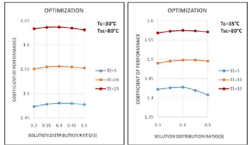
4.1 Optimization of Solution Distribution Ratio In The Double Effect Parallel Flow Cycle
The weak solution is distributed in double effect parallel flow cycle therefore it is important to find out optimum value of solution distribution ratio which yields maximum coefficient of performance. The maximum values of COP are plotted against solution distribution ratio at given conditions in figure 5. The maxima of the curve gives optimum value of solution distribution ratio.
Fig.5 Variation of COP with Solution distribution ratio for the parallel flow cycle for different values of
evaporator, condenser, and main condenser temperature
4.2 Coefficient Of Performance
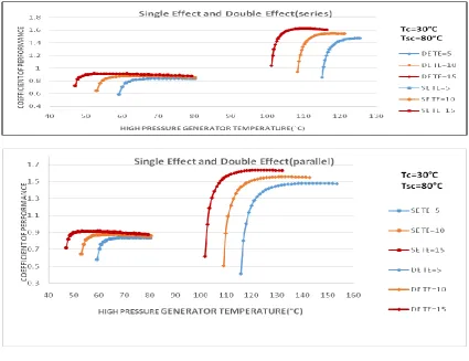
Figure 6 and 7 shows the variation in coefficient of performance of single and double effect (series, parallel
and reverse flow) cycles with generator temperature (to which heat is supplied) at different values of the
decrease of solution circulation ratio at slower rate at higher generator temperature. But at evaporator temperature of 5°C double effect (series flow) it is seen that the coefficient of performance of the absorption cycle increase drastically from low values at the low generator temperatures, reach to a maximum value and terminate. This is because, in the single effect cycle there is no limit, other than crystallization, in increasing the generator temperature. While, in the double effect cycle, the generator temperature and concentration will terminate when heat rejected in the secondary condenser balances the heat input to the secondary generator; the constant values appear more at high TC1. It is observed that maximum COP is found out in case of parallel flow (double effect cycle).One can also notice drastic increase in COP of the advance stage cycles, that is,
COPdouble> COPsingle. In double effect COPparallel>COPseries>COPreverse is observed.generator temperature then after achieving maximum value COP drops with further increase in generator temperature at evaporator temperature of 5, 10, 15 °C. The solution circulation ratio (i.e. ratio of mass flow rate of strong solution required per unit mass flow rate of refrigerant) is important for behaviour of COP. The increase in generator temperature results
Figure 6 Variations in COP of single effect and double effect(series and parallel) flow cycles with
generator temperature at different values of temperatures in the evaporator and the condensers at
various pressure levels
Figure 7 Variations in COP of single effect and double effect reverse flow cycles with generator
temperature at different values of temperatures in the evaporator and the condensers at various pressure
levels (Ta=Tc=30°C,Tsc=80°C.)
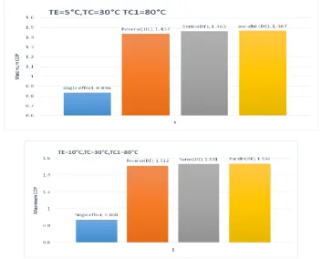
4.3 Comparision Of Maximum Cop
Figure 8 shows comparison of maximum COP in all four cycles i.e. in single effect, double effect (series,
parallel, and reverse flow) on bar graph at different evaporator temperatures and main condenser temperature of 30°C, and secondary condenser temperature of 80°C.COP is found out to be maximum in parallel flow cycle and least in single effect cycle i.e. COPparallel>COPseries>COPreverse>COPsingle effect.
Fig.8 Comparison of maximum coefficient of performance of single effect, double effect
(reverse flow, series flow and parallel flow) at different evaporator temperature and main &
V. CONCLUSIONS
1. The coefficient of performance of single effect, double effect series flow, reverse flow and parallel flow LiBr-H2O vapour absorption cycle increases with an increasing in generator temperature to which heat is supplied up to a certain limit and then decreases.
2. Lowering of the evaporator temperature and raising of the condenser temperature leads to decrease in the coefficient of performance for all the three cycles.
3. COP of double effect parallel flow cycle is greater among all the four cycles and single effect cycle having least.
4. Maximum COP of single effect cycle comes out to be 0.836 to 0.902, while for double effect series flow maximum COP comes out to be 1.455 to1.604, in case of reverse flow cycle it comes out to be 1.537 to 1.583 and for parallel flow 1.470 to 1.610 in case when main condenser temperature is 30°C and secondary condenser temperature is 80°C.
REFERENCES
Journal Papers:
[1] Kaushik S.C and Arora A (2009), “Energy and exergy analysis of single effect and series flow double effect water–lithium bromide absorption refrigeration systems”, International Journal of Refrigeration;32:1247-1258
[2] Seraj M, Siddique M. Altamush (2013), “Performance analysis of parallel flow single and double effect
absorption cycles”, International Journal of Innovative Research in Science, Engineering and Technology, Vol.2, Issue5,pp 1570-1576
[3] Arun, M.B., Maiya, M.P. and Murthy, S.S. (2001); “performance comparison of double effect parallel flow
and series flow water-lithium bromide absorption systems”. Applied Thermal Engineering,21:1273-1279
[4] Talbi MM, Agnew B. Exergy analysis: an absorption refrigerator using lithium bromide and water as working fluid. Applied Thermal Eng. 2000; 20:619–30
[5] Siddiqui M.A (1993), “Optimum generator temperature in four absorption cycle using different sources of
energy”, Energy conversion and management, No.24, pp. 251-266
[6] Kaita Y. Thermodynamic properties of lithium bromide-water solutions at high temperatures. International Journal of Refrigeration 2001; 24:374–390
Books:
1. Cengel Y.A and Boles M.A. “Thermodynamics an engineering approach”, 2008, Tata McGraw Hill Education Private Limited New Delhi
2. C.P. Arora “Refrigeration and Air Conditioning”, Tata McGraw Hill Education Private Limited New Delhi