using Multi-Lobe Beam Patterns
Adrian Loch
IMDEA Networks InstituteHany Assasa
IMDEA Networks Institute and Universidad Carlos III de MadridJoan Palacios
IMDEA Networks Institute and Universidad Carlos III de MadridJoerg Widmer
IMDEA Networks Institute [email protected]
Hans Suys
imec [email protected]Björn Debaillie
imecABSTRACT
Millimeter-wave devices must use highly directional antennas to achieve GBit/s data rates over reasonable distances due to the high path loss. As a consequence, it is important to precisely align the antenna beams between sender and receiver. Even minor movement or rotation of a device can result in beam misalignment and thus a strong performance degradation. Existing work as well as stan-dards such as IEEE 802.11ad tackle this issue by means of antenna sector probing. This comes at the expense of a significant overhead, which may significantly reduce the performance of millimeter-wave communication, particularly in mobile scenarios. In this paper, we present a mechanism that can track both movement and rotation of 60 GHz mobile devices with zero overhead. To this end, we transmit part of the preamble of each packet using a multi-lobe beampattern. Our approach does not require any additional control messages and is backward compatible with 802.11ad. We implement our scheme on a 60 GHz testbed using phased antenna arrays, and show that we reduce the angle error to less than 5◦in most cases. We also
perform simulations to validate our approach in a wide range of scenarios, achieving up to 2×throughput gain.
CCS CONCEPTS
•Networks→Mobile networks;Physical links;Network experi-mentation; •Hardware→Beamforming;
ACM Reference Format:
Adrian Loch, Hany Assasa, Joan Palacios, Joerg Widmer, Hans Suys, and Björn Debaillie. 2017. Zero Overhead Device Tracking in 60 GHz Wireless Net-works using Multi-Lobe Beam Patterns. InCoNEXT ’17: The 13th Interna-tional Conference on emerging Networking EXperiments and Technologies, December 12–15, 2017, Incheon, Republic of Korea.ACM, New York, NY, USA, 14 pages. https://doi.org/10.1145/3143361.3143395
Permission to make digital or hard copies of all or part of this work for personal or classroom use is granted without fee provided that copies are not made or distributed for profit or commercial advantage and that copies bear this notice and the full citation on the first page. Copyrights for components of this work owned by others than the author(s) must be honored. Abstracting with credit is permitted. To copy otherwise, or republish, to post on servers or to redistribute to lists, requires prior specific permission and/or a fee. Request permissions from [email protected].
CoNEXT ’17, December 12–15, 2017, Incheon, Republic of Korea
© 2017 Copyright held by the owner/author(s). Publication rights licensed to Associa-tion for Computing Machinery.
ACM ISBN 978-1-4503-5422-6/17/12...$15.00 https://doi.org/10.1145/3143361.3143395
1
INTRODUCTION
+1
+1
‒
1
+1
+1
‒
1
+1
+1
‒
1
Rotation to the left
Rotation to the right
Correct alignment
TX
RX
TX
RX
TX
RX
1
stpreamble half 2
ndpreamble half
Data transmission
+1 +1 +1 +1‒1 +1 +1
Misalignment cases
Figure 1: Toy example of our device tracking mechanism.
retraining, most approaches only react to SNR dropsafterthey occurred, causing transient link degradation and interruptions.
In this paper, we present a device tracking mechanism for IEEE 802.11ad that incurs zero overhead. Moreover, it does not rely on SNR measurements to detect beam misalignment but continuously adjusts the beam-steering as the user moves. Our approach can track both Line-Of-Sight (LOS) and Non-Line-Of-Sight (NLOS) paths, thus being suitable for scenarios with blockage. We only perform one initial beam-sweep to find the path. After that, we can track it as long as the path changes gradually. Abrupt changes are due to sudden blockages. Finding a new path during such a blockage is an orthogonal problem to tracking a given LOS/NLOS path, and thus out of scope of this paper. However, we discuss the impact of this problem in our evaluation in Section 4.2. Further, our scheme does not require any feedback but operates on each node indepen-dently. We do not modify the 802.11ad protocol. Thus, a device implementing our mechanism is fully backward-compatible with regular 802.11ad nodes. More importantly,a device still benefits from our approach when communicating with a regular node.
The key idea of our mechanism is to use a beam pattern with two strong adjacent lobes (Figure 1) instead of just one main lobe when receiving part of the preamble of each packet. The rest of the preamble as well as the headers and the data payload of the packet are received with a regular beam pattern, as shown at the top of Figure 1. Recent work [8, 9] shows that such fast switching among beam patterns is feasible in practice. The segment of the preamble that the node receives with the two-lobe beam pattern allows to infer whether the node has rotated or moved. To this end, we design our two-lobe beam pattern such that the signal received via one of the lobes has a 180◦phase shift compared to the other
lobe, indicated by +1 and -1 in the figure. This is feasible with a conventional phased array and a single transmit chain since the phase shift is due to the beam pattern itself. By comparing the phase of the first half of the preamble to that of the second half, we can deduce whether the node received the second half primarily via the positive or the negative lobe. This reveals whether a rotation
has taken place. As shown in Figure 1, a rotation to the left results in both preamble parts being in phase, whereas a rotation to the right results in a 180◦phase shift. Further, correct alignment results
in very low received signal strength, which we can easily detect. In this case, the receiver only receives half of the preamble, but we show that this does not compromise signal acquisition quality (c.f. Section 2.2.3). Depending on the outcome, the receiver steers the beam to the right, to the left, or not at all. The same principle is valid not only for data packets but also for acknowledgments, allowing both sides of the link to track one another. The undesired side-lobes of practical beam patterns do not hinder the operation of our scheme since they do not point to the transmitter. We validate this in our practical experiments. Since our mechanism operates on the regular 802.11ad preamble, it does not incur any additional overhead. Our design becomes even more important for future antennas with higher number of elements and narrower beam width. Such antennas incur an even higher steering overhead with conventional approaches, while they allow to design more fine grained multi-lobe patterns and thus more efficient preamble based beam steering.
For our design, we leverage several physical layer effects inherent to mm-Wave communication:
(1) Beam Pattern Design.Conventional phased arrays allow to design multi-lobe beam patterns with a pre-defined phase shift among the lobes. We exploit this characteristic to trans-mit a signal with 0◦and 180◦phase shift simultaneously.
(2) Indoor Propagation.Due to the high absorption of walls, 802.11ad Access Points (APs) typically cover a single room only. We show that this results in a sufficiently high SNR to allow signal acquisition with only the first part of the preamblewhen the antenna beams are roughly aligned. In case of strong misalignment, we resort to the full preamble. (3) Correlation Properties.The excellent correlation proper-ties of the Golay sequences in the 802.11ad preamble [22] allow to reliably estimate the phase shift between the first and the second preamble half even at very low SNRs. This enables our system to work even if the lobes of the two-lobe beam are relatively far apart (c.f. Section 4.1.2).
We build on these effects to implement zero-overhead mm-Wave device tracking. Our contributions are as follows:
• We design a mechanism that enables accurate rotation and movement tracking on a per-packet basis, without incurring any control overhead.
• We present a method to infer link changes by detecting phase inversion compared to a reference phase in the 802.11ad packet preamble.
• Our mechanism is fully backward compatible and works when communicating with legacy 802.11ad devices. It only requires changes to the antenna pattern with which packet preambles are received.
• We evaluate the steering accuracy of our approach in practice using 60 GHz electronically steerable antenna arrays. For most cases, our error is below 5◦.
2
DEVICE TRACKING
We consider indoor scenarios such as home or office environments. Our tracking mechanism supports both infrastructure-based net-works as well as individual point-to-point connections. In the for-mer case, one of the nodes is an AP installed at a fixed location near a wall. Nodes may rotate and move along arbitrary trajectories.
2.1
General Operation
Similarly to 802.11ad, we require a beam-sweep to establish a con-nection between two devices. This allows both endpoints to find the strongest path between them, which may be LOS or NLOS. We donotrequire this initial sweep to be very precise. Our ap-proach naturally corrects for initial misalignment, if present. After the beam-sweep, the devices start with the data exchange. Since 802.11ad includes physical layer acknowledgments, the nodes ex-change frames in both directions, allowing both endpoints to track one another. That is, our mechanism works regardless of the di-rection of upper-layer traffic. The operation is identical for the infrastructure-based case and the point-to-point case. The track-ing takes place at each device individually and does not require any feedback. This does not assume symmetry regarding the beam patterns used on each side, since each device tracks its own Angle of Arrival (AoA). The receiver uses the AoA obtained from each packet to adjust its transmit and receive beam for thenextdata packets and acknowledgments. Thus, the rate at which the receiver can adjust for AoA changes is equivalent to the rate at which it receives packets. We discuss this in detail in Section 2.3.
2.2
Exploiting Preambles in 802.11ad
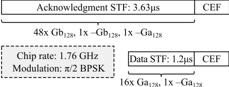
Our approach is tailored to 802.11ad to be backward compatible with existing devices and avoid any change to the standard. Rotation and movement estimation is based on standard-compliant frames. For each transmitted frame, the receiver infers its relative rotation from the preamble of the data packet. Conversely, the transmitter does the same based on the preamble of the corresponding physical layer acknowledgment. In both cases, the preamble consists of a Short Training Field (STF) and a Channel Estimation Field (CEF) [22], as depicted in Figure 2. The STF allows for packet detection, and the CEF is used to estimate the channel impulse response of the path currently in use. The CEF is identical for both data packets and acknowledgments whereas the STF is longer for the latter to improve robustness.
2.2.1 Short Training Field Structure.For brevity, in the follow-ing we focus on data packets only. Due to the short length of their STF, this case is more challenging compared to the case of acknowl-edgments. Still, the subsequent discussion applies to both. The STF of a data preamble consists of seventeen Golay sequences [14]. These sequences have excellent correlation characteristics, which 802.11ad exploits to reliably detect arriving packets. Essentially, the receiver computes the cross-correlation of incoming samples with a standard Golay sequence. If the samples include the preamble of a packet, the cross-correlation results in a strong spike that the receiver can easily detect. The seventeen sequences are so-called Ga128sequences, which have a length of 128 bits. The last sequence is inverted to account for multi-path effects in the CEF.
Chip rate: 1.76 GHz
Modulation: π/2 BPSK
CEF
CEF
Acknowledgment STF: 3.63μs
Data STF: 1.2μs
48x Gb
128, 1x ‒Gb
128, 1x ‒Ga
12816x Ga
128, 1x ‒Ga
128Figure 2: Preamble of acknowledgment and data packets as defined in the IEEE 802.11ad standard.
2.2.2 Beam Switching.When using our device tracking mecha-nism, a receiver switches to the two-lobe beam pattern after receiv-ing eight out of the sixteen Golay sequences, as sketched in Figure 1. The specific timing of the beam switching is strongly implementa-tion dependent, since it is closely related to the switching time of the antenna. The faster the switching, the more Ga128sequences the receiver can receive before switching to the two-lobe beam pattern. The sequences receivedduring the switching itself are discarded, since the beam pattern is in an unknown state. Strictly speaking, our mechanism only requires that the receiver receives one Ga128 se-quence via each of the two beam patterns. However, receiving more than one allows for averaging, which in turn improves accuracy. The receiver must have switched back to the regular single-lobe beam pattern before the seventeenth Golay sequence. The underly-ing reason is that 802.11ad uses the last sequence of the STF as well as the full CEF to estimate the Channel Impulse Response (CIR). If the receiver receives part of it via the two-lobe beam pattern, the resulting CIR is wrong. This impairs channel equalization and the receiver would not be able to decode the payload data. Ideally, the beam switching time should be less than 70 ns, that is, the duration of one Golay sequence. State-of-the-art antennas achieve switching times below 50 ns [53], and switching times as low as 50 ps can be achieved with better designs [8, 9]. This time includes changing all of the antenna weights, and stabilizing at the new beam pattern. Even slower antennas with switching times of a few hundred ns can be supported, at the expense of fewer Golay sequences available for averaging. Thus, switching among two beam shapes during the STF of an 802.11ad data frame is feasible. For acknowledgments, this constraint is even further relaxed.
2.2.3 Preamble Robustness.In the worst case, a receiver using our tracking mechanism only receives half of the STF. This occurs when the use of the two-lobe beam pattern results in a very low SNR, and the receiver cannot detect any of the Ga128sequences in the second part of the STF. Even in this case, the node still receives the first part of the STF as well as the CEF and the data payload, which typically allows for packet decoding. However, it degrades the robustness of the preamble since, in the worst case, the receiver must be able to detect the packet based on half of the Ga128 sequences. If interference or low SNR prevent the detection of some of the sequences, the receiver may miss the packet. To assess this risk, we study the impact of removing half of the preamble both in simulation and in practice using COTS 802.11ad hardware.
-30 -20 -10 0 10 20 30 SNR (dB)
0 4 8 12 16
Detected Ga
128
seq.
Figure 3: Average number of Ga128sequences detected in the STF of an 802.11ad frame for a range of SNRs.
in the detection of less than eight sequences. Since 802.11ad APs typically cover a single room only, such a low SNR due to path loss is unlikely [43, 47, 51]. A simple back-of-the-envelope calculation using Equation 1 reveals that an indoor link would have to be 27 meters long to fall below 4 dB of SNR. This is uncommon in indoor environments, particularly for short-range 60 GHz communication. Hence, the impact of our mechanism on robustness is negligible. While we use the simple path loss model in Equation 1 for this estimation, note that Section 4.2 is based on detailed ray-tracing.
PR=PT+GT+GR+20 log10
λ 4π R
(1)
where PRis the received power, PTthe transmitted power, GTthe transmit antenna gain, GRthe receive antenna gain,λthe wave-length at 60 GHz, andRthe link length. We obtainRbased on the Equivalent Isotropically Radiated Power (EIRP) allowed for the 60 GHz band, and assume a receiver noise factor of 10 dB [22].
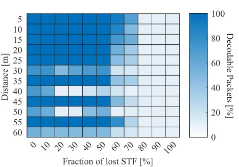
To validate our simulative analysis, we carry out a practical measurement campaign using COTS hardware. We use a TP-Link Talon AD7200 router to transmit 802.11ad frames. Since we do not connect the router to any station, the router periodically transmits a sequence of beacon frames to announce its presence to potential stations. We capture those beacons with a Sivers IMA FC2221V/01 V-band converter attached to a Keysight DSOS254A oscilloscope. Since the bandwidth of the oscilloscope is 2.5 GHz, we can decode the received beacons in post-processing. To this end, we use the Keysight Wideband Waveform Center, which implements a full IEEE 802.11ad decoder. Prior to decoding, we substitute part of the preamble with white Gaussian noise. In particular, we compare the impact of loosing 0% to 100% of the STF in steps of 10%. To assess the impact of low SNRs, we repeat the experiment at different distances ranging from 5 meters to 60 meters. In order to reach such long indoor link distances, we carry out the measurements in a long corridor using a 7◦horn antenna. We also perform the
experiment with a 20◦antenna but results are equivalent except
for the shorter overall range of the communication.
Figure 4 depicts the result of the experiment for multiple link distances and STF fractions. We capture 30 frames for each link distance, and compute as a percentage how many of them are de-codable. We consider that a frame is decodable when the Keysight Wideband Waveform Center (a) detects the packet, and (b) reports that the decoded bytes pass the codeword parity check. Figure 4 reveals that performance decreases as soon as a frame lacksmore than50% of the STF. However, for 50% or less, frames are fully decodable. This trend holds for distances up to 25 to 30 meters, as
0 10 20 30 40 50 70 80 90 100 Fraction of lost STF [%] 5
10 15 20 25 30 35 40 45 50 55 60
Distance [m]
0 20 40 60 80 100
Decodable Packe
ts [%
]
60
Figure 4: Percentage of decodable frames for multiple link distances and lost STF fractions (0%stands for a full STF).
predicted in our simulation study. Beyond that distance, Figure 4 re-veals an alternating pattern of decodable and non-decodable frames. This is due to the impact of reflections in the corridor that cause constructive and destructive interference. Most importantly, we observe that reducing the length of the STF up to 50% has a very limited impact on the decoding of frames. Thus, we conclude that the potential loss of half of the STF is not critical.
2.3
Tracking Speed
Nodes can track each other at the rate at which they receive frames at the physical layer (c.f. Section 2.1). That is, our device tracking ap-proach works whenever data is being exchanged. Otherwise, nodes resort to a single beam-sweep when the communication resumes, and then continue tracking each other according to our mechanism. The tracking speed is thus related to the amount of traffic on the link. However, as a result of the large amount of frames exchanged in 802.11ad, our system can easily track typical indoor human mo-bility. As an extreme example, consider a transmitter and a receiver located at a distance of only 0.1 meters that use very narrow beams with a beam width of only 7◦. This is a worst case scenario, since
any slight movement or rotation results in a strong misalignment. Assuming that one of the nodes moves at the maximum human walking speed described in the literature (3 m/s [29]), we can easily compute that the nodes are out of the boresight of each other after 2.03 ms. Thus, the system needs to transmit at least one frame every 2.03 ms to be able to track the movement. Frame size plays a role because larger frames result in less preambles being transmitted per time unit. However, even assuming the highest level of A-MSDU frame aggregation in 802.11ad (7935 bytes [22]), this would only require a data stream of about 30 megabits per second. For typical indoor walking speeds and link distances, this limitation is relaxed even further. Thus, frame rate and size have a negligible impact on the operation of our device tracking mechanism.
2.4
Golay Sequence Phase Detection
Increase
estimated
AoA
Obtain Ga
128sequence via one-lobe beam pattern
Obtain Ga
128sequence via two-lobe beam pattern
Compute cross-correlation of both sequences
Adjust AoA of beampatterns for next packet
Decrease
estimated
AoA
Keep
estimated
AoA
Figure 5: Basic operation of our tracking mechanism.
switching time allows the receiver to capture multiple sequences with each beam pattern (c.f. Section 2.2.2), the receiver can aver-age them to reduce the impact of noise. Still, this is not strictly needed due to the inherent robustness of Golay sequences. These sequences are essentially a sequence of ones and minus ones. A straightforward approach to compare two such sequences would be to compute the phase of each pair of symbols in a symbol-by-symbol manner. However, this is challenging because the receiver receives each of the two sequences with a different beam pattern. While both beams point roughly in the same direction and use the same LOS or NLOS path, they result in different CIRs due to their different shape. Thus, the phase shift among the two sequences is not exactly 0◦or 180◦, but often lies somewhere in between.
More-over, we cannot correct the impact of the different CIRs, since we only obtain the CIR for the one-lobe beam pattern (c.f. Section 2.2.2). To tackle the above issue, we exploit the properties of Golay sequences. Basically, we compute the cross-correlation of the se-quence obtained via the one-lobe beam pattern, and the sese-quence ob-tained via the two-lobe beam pattern. If the sequences are in phase, the cross-correlation results in a large positive spike. Conversely, if the sequences are shifted by 180◦, the cross-correlation yields a
large negative spike. Intermediate states stemming from channel distortions reduce the size of the spike, but the cross-correlation usually reveals a clear trend. This allows us to easily identify the direction of rotation and/or movement. Figure 5 depicts the basic diagram of our device tracking mechanism. Based on the sign of the cross-correlation spike, we adjust the estimation of the AoA of the signal for the next packet. If the cross-correlation does not result in a spike, we keep the current AoA. This typically occurs when the AoA is close to the optimal alignment. In that case, the node receives the second half of the STF via the null of the two-lobe beam pattern, resulting in noise. Thus, no AoA adjustment is needed.
This simple yet highly effective approach is the core of our device tracking mechanism. It leverages the properties of Golay sequences, and works even for very low SNRs. In practice, our scheme faces a few more challenges, which we address and discuss in Section 3.
2.5
Adaptive Rotation Step
The rotation step is the angle by which we increase or decrease the AoA estimate based on the outcome of the preamble correlation. If it is too small, the system cannot track the device fast enough. If it is too large, the system overshoots the range of suitable AoA values. Fortunately, the rough value of the rotation step depends to a large extent on the resolution of the phased antenna array, and thus can be set to a constant value in most cases. The minimum beam width of the beam patterns that the antenna can generate determines the step at which our system must track rotation and movement. For instance, if the antenna beam width is 20◦, misalignment below that
value has a small impact. To avoid undesired SNR drops in case of noisy AoA estimates (c.f. Section 3.2), a rotation step value of about half of the antenna beam width is suitable. In other words, our system doesnotrequire a minimum antenna steering granularity but can be adjusted to the specifics of each antenna.
Movement at highly variable speeds may still benefit from fine-grained adjustment of the rotation step. We sketch an adaptive mechanism that adjusts the rotation step flexibly. If the system is not tracking a device fast enough, Figure 5 results in a long sequence ofniidentical decisions—it either continuously increases or decreases the AoA. In contrast, if we overshoot the actual angle, the mechanism alternates between increasing and decreasing the AoA. We define the number of such consecutive switches asns. The rotation step is well adjusted whenniandnsare close to zero. Thus, we define the misadjustmentmas in Equation 2, where tunable parameterαcontrols the impact of such misadjustments.
m=(ni−ns)α (2)
Adjusting the rotation step as a function ofmallows our system to adapt to highly variable movement and rotation speeds. We implement and validate this approach, but do not discuss it further in this paper due to space constraints.
2.6
Two-Lobe Beam Pattern Generation
Our device tracking mechanism builds on the beam forming capa-bilities of 60 GHz devices. For each potential receive direction, our mechanism requires two beam patterns, namely, the conventional one-lobe beam pattern and our custom two-lobe beam pattern. To implement this in practice, devices would simply use a larger code-book of beam patterns encompassing both types. Our approach assumes a conventional analog beam forming architecture [34]. That is, the system can operate with a single radio-frequency chain, unlike more complex fully digital or hybrid architectures. Analog beamforming allows us to set arbitrary phase shift and amplitude control values at each antenna element. Such control is not only pos-sible on lab hardware but also on commercial off-the-shelf devices such as the WilocityWil6200cards [12, 39], which are the most
widespread 60 GHz wireless cards for consumer hardware. The Wilocity cards allow for amplitude control, but this is not strictly needed to form two-lobe beam patterns [34]. Two-lobe beam shapes are feasible even with one-bit phase shifters [59]. Adding one bit more allows also for 180◦phase shift among lobes [34]. That is, our
and 4, whereNis the number of antennas andϕeis the estimated AoA. That is, the beam points towards the estimated AoA.
wn′ =ejπ ncosϕe (3) wn=wn′/wn′ (4)
We compute the weights of our two-lobe beam pattern as the sum of two one-lobe beam patterns, as shown in Equations 5 and 4. The sum becomes a subtraction because the phase of the second lobe is inverted. The minus sign in Equation 5 is the key to the 180◦
phase shift sketched in Figure 1.
wn′ =ejπ n(cosϕe+2rN) −ejπ n(cosϕe−2rN) (5)
Equation 5 results in a beam pattern with a null in the direc-tion of the AoA. If the estimated AoA is noisy, the beam may be slightly misaligned. Our mechanism inherently corrects for this (c.f. Section 3.2). Parameterrin Equation 5 controls the relative angle among the two lobes. If the angle is large, the receiver takes longer to detect a rotation/movement. If the angle is too small, the lobes merge and thus the phase of the Ga128sequences may not exhibit a clear trend. Our evaluation shows thatr=0.75 works well.
2.7
Handling Obstacles
In 60 GHz communication, obstacles typically fully block the signal. As a result, the current path becomes unavailable. In this case, our mechanism resorts to a beam sweep to find an alternative path, such as a strong reflection. We then track the reflection in exactly the same way as the previous LOS path. That is, our mechanism does not need to be aware of whether the current path is LOS or NLOS. In both cases movement and rotation lead to equivalent angle changes. In typical home or office scenarios, blockage events take place at rather large timescales, that is,seconds. In contrast, rotation and movement happen continuously at the timescale ofmillisecondsas a user handles a device. Thus, the overhead of triggering an individual beam sweep when blockage occurs is negligible compared to the effort required to track the rotation and movement of a user as in 802.11ad, that is, using continuous beam sweeps. Our approach eliminates the need for the latter, thereby incurring zero overhead.
3
PRACTICAL CHALLENGES
In the following, we discuss practical lessons that we learned from testbed experiments and that have impacted our design.
3.1
Antenna Structure
We design our mechanism such that it can track a device across the entire azimuthal range of 360◦. However, practical 60 GHz devices
usually cover less than 180◦because the antenna is attached to a
specific side of the device. In other words, the device blocks itself. Our mechanism can operate on such a device without any modifi-cation. While it can only circumvent the blockage if a reflection is available, this is inherent to mm-Wave and not a limitation of our design. For the simulative evaluation in Section 4.2, we use a device model with one antenna on each of the sides of the device to cover 360◦. This is not possible in our practical setup since it consists of
a single antenna array. Thus, we limit the device rotation in our testbed experiments to[−45◦,+45◦].
3.2
Beam Pattern Imperfections
Due to hardware limitations, the two-lobe beam pattern of a re-ceiver may not be perfectly aligned to the transmitter even if the single-lobe beam is. As a result, the system detects a misalignment and corrects the orientation of both patterns. The impact of this noisy AoA estimate depends on the value of the rotation step. As discussed in Section 2.5, we choose the rotation step to be smaller than the beamwidth of the main lobe. Thus, even if a noisy AoA estimate causes a slight misalignment of the single-lobe beam, the transmitter is still within the main lobe of the receiver. In Section 4.1, our practical experiments show that this effect takes place, and that it may lead to a harmless fluctuation of the AoA within the safe limits of the beam width of the main lobe (c.f. Figure 10).
3.3
Phase Impairments
As discussed in Section 2.4, we exploit the correlation properties of Golay sequences to estimate whether the sequences received via the one-lobe and the two-lobe beam patterns are in phase or counter-phase. The first concern is Carrier Frequency Offset (CFO), which is a slight but inevitable frequency mismatch of the reference clocks at the transmitter and at the receiver. This mismatch causes a phase drift throughout the packet, which also shifts the relative phase of the symbols in the first and in the second part of the preamble. As a result, comparing their phases becomes harder. Fortunately, we can apply the same CFO correction techniques used for 802.11ad. After receiving the packet, the receiver estimates and corrects the CFO on all symbols, including the two halves of the preamble. The second concern is that the result of the cross-correlation of the received complex signal samples and the Ga128sequence is again complex. For 802.11ad this is not a problem since signal detection is based on detecting spikes in the absolute value of the above cross-correlation. However, our approach must detect thesignof the spike. Thus, it cannot operate on the absolute value. This means that we must perform channel equalization on the received Golay sequences, but as mentioned in Section 2.4, the CEF only allows us to compute the CIR for the case of the one-lobe beam pattern.
−0.01 0 0.01
−0.01 0 0.01
-0.01 0 0.01
-0.01 0 0.01
IQ [V] IQ [V]
Figure 6: Two independent examples of k-means clustering of received preamble samples from our testbed.
3.4
Cumulative Errors
Practical issues such as hardware impairments, measurement errors, and amplifier saturation are unavoidable in testbed and real-world operation. Such issues can result in a wrong estimate of our tracking mechanism. In the best case, the cross-correlation results in noise and our tracking mechanism keeps the same AoA as for the current packet. However, in some cases the system may classify such cases wrongly, resulting in incorrect AoA estimations. The key problem is that such errors are cumulative, since the next estimation is biased by the output of the current one. In the worst case, errors that add up may lead to a strong misalignment. While the resulting SNR drop would trigger a beam-sweep that would correct the error, a performance degradation is inevitable. To prevent this behavior, devices can use existing techniques to deal with noisy estimates [24]. A straightforward approach is to obtain multiple measurements and update the AoA based on the mode of those estimates. While this introduces a tracking delay, in practice the impact is negligible since we obtain a new AoA estimate with each packet that a node receives. Given the high rates in 802.11ad, nodes obtain many more estimates than needed to track human indoor mobility.
4
EVALUATION
We perform both a practical and a simulative evaluation of our de-vice tracking mechanism. The practical part in Section 4.1 validates that our approach is feasible using an actual electronically steer-able phased antenna array. The simulative part of our evaluation in Section 4.2 allows us to assess a broad range of scenarios and thus generalize our insights. Finally, in Section 4.3, we compare the performance of our mechanism to existing approaches.
4.1
Practical Evaluation
We implement our tracking mechanism on an electronically steer-able phased antenna array developed at imec Belgium [27]. We carry out all of our experiments at the imec laboratories. We first describe the testbed and then delve into the experimental results.
4.1.1 Testbed Setup.The 60 GHz testbed at the imec radio fre-quency laboratory consists of a transmitter and a receiver. Both devices operate on the standard 802.11ad channels, and each one features a 2×8 phased antenna array [27] formed by four imec PHARA4 modules [23]. The resolution of the phase and amplitude control of each antenna element is eight bits. While the scanning granularity of the antenna is below 1◦, our approach doesnot
re-quire such a high resolution (c.f. Section 2.5). Figure 7 depicts the
Figure 7: imec’s2×860 GHz electronically steerable phased array antenna [27]. Each pair of patches is one element.
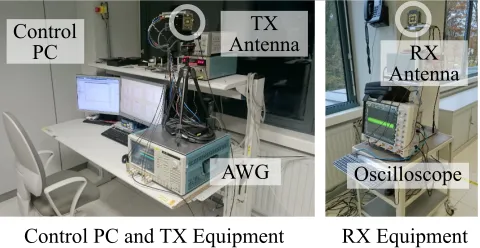
Control PC and TX Equipment
Control
PC
AWG
TX
Antenna
RX Equipment
RX
Antenna
Oscilloscope
Figure 8: Full-bandwidth 802.11ad testbed. Transmitter and receiver are separated by about four meters. This distance is fixed due to the specifics of the lab environment at imec.
-30º -15º 0º
15º 30º
0 1
2 3
4
RX Power [W
x10 -5] -30º
-15º 0º
15º 30º
0 1
2 3
RX Power [W
x10 -4 ]
(a)
(b)
Figure 9: Measured beam patterns. In beam pattern (a), the left lobe is positive and the right lobe is negative.
beam pattern. Our tracking mechanism operates identically but requires the involvement of both sides. This limitation is given by the experimental setup in the lab, which we cannot modify. Figure 8 shows our setup in the lab including all of the elements described above. The window in the back of the pictures acts as a surprisingly strong reflector. Other lab objects cause reflections, too. That is, we validate our mechanism in a multi-path environment.
4.1.2 Experimental Results. We first validate that we can gen-erate a two-lobe beam pattern on our testbed. We then use a real-world gyroscope trace to test that our approach works. Finally, we perform a misalignment study to evaluate its performance.
Beam Pattern Generation.Figure 9 depicts the measured two-lobe and one-two-lobe beam patterns that we generate in our 60 GHz testbed. This shows that we can successfully generate the desired beam shapes in practice. Although the two-lobe beam is relatively wide, this does not necessarily sacrifice accuracy. Our results in this section show that we can track even slight rotations. The reason is that the Golay sequence correlation results in a clear spike even if we only receive a small amount of energy of one of the lobes when the misalignment has not yet reached the peak of the lobe.
Tracking Example.Next, we let the transmitter gimbal rotate ac-cording to a gyroscope trace of a person walking [44]. As discussed in Section 3.4, we take each rotation decision based on the mode of multiple measurements to avoid cumulative errors. In this case, we take the mode every five measurements, and use a rotation step of 2◦. Figures 10 and 13 show that we can clearly identify and follow
the rotation. Our AoA estimation lies in nearly all cases within the beamwidth of the single-lobe beam pattern. Thus, we obtain uninterrupted high throughput despite the rotation without costly beam sweeping. In Figure 13 we observe a slight tracking error aroundt=0.5sbut our mechanism quickly recovers. The tracking resolution and accuracy is directly related to the beamwidth that the antenna uses. If an antenna uses narrower beams for the single and multi-lobe beams, the shaded area in Figure 10 becomes nar-rower but also the tracking accuracy improves. Conversely, wider beams would relax the constraints on the tracking accuracy. In other words, our system adapts to the capabilities of the antenna. Misalignment Study.To understand the impact of misalignments and thus derive the accuracy that we need to ensure high-throughput communication, we measure the 802.11ad Bit Error Rate (BER) for
0 0.5 1 1.5 2 2.5 3
Time [s] -30
-20 -10 0 10 20
Device Rotation [º]
Beamwidth Tracked Rot.
Actual Rot.
Figure 10: Tracking example for a gyroscope trace of a per-son walking. The rotation trace is taken from [44].
Table 1: BER and SNR for increasing misalignment
Misalignment 0◦ 2◦ 4◦ 6◦ 8◦ 10◦ 12◦
BER <10−3 <10−2 0.28 SNR [dB] 18 18 17 17 16 13 6.57
Rate [Gbps] 2.5 2.3 1.5 0
a range of misalignment values. Table 1 shows our results. We observe that up to a misalignment of 10◦, the BER is low.
How-ever, at 12◦the BER increases by more than 30×, reaching up to
roughly 28% and thus causing outage. That is, to ensure proper operation of the link, we must achieve an angle error below 10◦.
To validate that our device tracking mechanism is able to achieve this, we perform a misalignment study in which we let the gimbal periodically increase and decrease the misalignment according to a sinusoid. Whenever outage occurs, we trigger a beam-sweep. After the sweep, the beams are well aligned. However, rotation continues resulting again in misalignment.
Figure 11 depicts the evolution over time of the rate as the gimbal rotates for both a sinusoidal rotation of 10◦and 20◦. As predicted in
Table 1, for the 10◦case neither 802.11ad nor our mechanism cause
outage. However, 802.11ad operates at the limit since it is agnostic to the rotation and thus occasionally reaches 10◦misalignment. As
a result, we observe significant link rate degradation for 802.11ad in Figure 11(a). In contrast, our mechanism successfully tracks the rotation and thus achieves a stable rate of 2.5 Gbps. For rotations up to 20◦misalignment, Figure 11(b) shows that 802.11ad causes outage
frequently. Due to the misalignment, the link rate degrades to zero and 802.11ad must trigger costly beam-sweeps. In contrast, our device tracking mechanism avoids misalignments larger than 10◦,
Rate [G
b/s]
Time [s] Time [s]
Rate [G
b/s]
Device Tracking 802.11ad
3
2
1
00 0.25 0.50 0 0.25 0.50
3
2
1
0O O O O
(a) (b)
R
Figure 11: Physical layer rate for (a)10◦and (b)20◦rotations. Each “O” marks an outage of 802.11ad. The shaded area “R” indicates the impact of a reflection on a nearby window.
0 2 4 6 8 10 12
Rotation [º]
An
gle E
rro
r
[º
]
5 10 15 20 25 Max. Allowable Angle
Error (c.f. Table I)
Figure 12: Angle error of our tracking mechanism for dif-ferent sinusoid amplitudes.
0 1
Time [s] -20
-10 0 10 20 30
Device Rotation [º]
Beam Tracked Actual
0.5
Figure 13: Tracking example on a real-world gyroscope trace with error recovery.
both sides can track one another, such a degradation would not occur. For both experiments in Figure 11 we also observe occasional small ripples. This is due to the few cases for which our mechanism looses track of the rotation due to multiple subsequent estimation errors (c.f. Section 3.4). In our testbed, the capture delay of the oscilloscope constrained our measurements to five estimates per step, thus resulting in these rare but present errors. On production hardware, the high amount of packets per time unit would result in many more estimates per step, allowing the system to statistically identify errors. Finally, in Figure 12 we show the average error for further amplitude values. Overall, we are able to keep the angle error below 10◦and thus can maintain high link throughput.
4.2
Simulative Evaluation
To complement our practical experiments, we implement our device tracking mechanism in Matlab using standard-compliant 802.11ad signals as a basis. Further, we use the resulting SNR and MCS traces as input to the ns-3 simulator [42]. This allows us to understand the impact of rotations and movement not only at the physical layer but throughout the protocol stack for a wide range of scenarios.
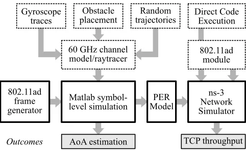
4.2.1 Simulation Setup. Figure 14 depicts the architecture of our simulator. It consists of a symbol-level part and a packet level part. The former is based on Matlab and the latter on ns-3. As a result, we obtain an accurate model of the physical layer while at the same time understanding the impact on the transport layer.
802.11ad frame generator
Matlab symbol-level simulation 60 GHz channel model/raytracer Gyroscope
traces
AoA estimation
PER Model
ns-3 Network Simulator Direct Code
Execution
802.11ad module
TCP throughput Random
trajectories Obstacle
placement
Outcomes
Figure 14: Architecture of our full protocol stack simulator. Bold boxes indicate the simulation tool-chain, dashed boxes are inputs, and gray boxes are outputs.
Symbol-Level Simulation.Our simulator considers indoor sce-narios. At the beginning of the simulation, we generate random spline-shaped node trajectories within a room. Further, for certain scenarios (c.f. Section 4.2.2) we add a given number of obstacles at random locations. We use a real-world dataset of mobile phone gyroscope traces [44] to obtain realistic values for the rotation of the nodes as they move on the generated trajectories. Based on these inputs, we use a publicly available ray-tracing tool specifically designed for 60 GHz communication [46] that builds on the 60 GHz channel models defined in the 802.11ad standard [26] to obtain the full channel description for our scenario. That is, we obtain all available paths including multiple-order reflections as well as AoA and Time of Arrival (ToA) values. We then compute the beam patterns for the current AoA according to Section 2.6, and use the channel from the ray-tracer to obtain the CIR for each beam pattern. Next, we use an 802.11ad Waveform Generation API [30] to obtain the IQ samples of a standard-compliant physical layer frame. We compute the convolution of the frame with the channel to obtain the received IQ samples, and process it according to our device tracking approach. Moreover, we obtain the SNR and MCS of the frame. Starting from the ray-tracing, we repeat the full process for each frame that the nodes exchange.
Accuracy Gain [%
] No Obstacle, Large Room
PTP AP
AP, Two Obstacles
Large R. Small R. 0
20 40 60 80
0 20 40 60 80
Figure 15: Angle error improvement in simulation.
infrastructure-based scenarios (c.f. Section 4.2.2), we also use ns-3 to model a backbone network and a remote server. The delay to reach the server is 40 milliseconds. In all of our scenarios, we use theBulkSendApplicationof ns-3 at the application layer, which
behaves similarly to a File Transfer Protocol (FTP) server. As a result, we obtain the TCP throughput for each of the trajectories that we generate in the symbol-level part of the simulation.
4.2.2 Scenarios. To generate our scenarios, we consider three basic parameters: size of the room, type of the network (AP or point-to-point), and type of obstacles. As a baseline mechanism, we recreate the behavior of 802.11ad. That is, whenever the SNR decreases due to misalignment or blockage, the baseline performs a beam-sweep to correct for the misalignment or find a new path.
Room Size.The room size has a direct impact on the strength of the reflections. We consider medium rooms with a size of 7×7 meters such as open-plan areas in offices, and large rooms with a size of 15×15 meters such as a conference hall.
Network Type.We consider both infrastructure-based and point-to-point scenarios. In the point-point-to-point case, two mobile devices communicate within the same room. Both follow arbitrary trajecto-ries. In the infrastructure-based case, we place an AP in a randomly chosen corner of the room, and let the mobile device move on an arbitrary trajectory. This mimics a scenario where a user is access-ing a remote server on the Internet via 802.11ad. The key difference among the two network types is that the delay is much higher in the infrastructure-based case. While TCP recovers quickly in the point-to-point case due to the low delay, the impact of SNR fluctuations is much higher in the remote server case.
Blockage Type.We generate scenarios both with and without blockages at random locations. Their size is 1×1 meters, and the default material is metal. We also consider self-blockage scenarios. In this case, we model a person holding a phone as a mobile obstacle that follows the node movement. The material is such that it absorbs most of the energy, similar to a human. The size of the obstacle is 0.3×0.875 meters, based on the average human size [31].
4.2.3 Results.For readability and conciseness, in the following we refer to the infrastructure-based case as the AP scenario and to the point-to-point case as the PTP scenario.
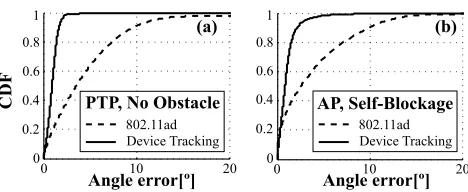
Steering Accuracy.Our mechanism improves steering accuracy significantly. Figure 15 shows by how much we reduce the angle error for four different scenarios. In the case without obstacles, we improve accuracy by nearly 80% for both PTP and AP. The gain
CDF
Angle error[º] Angle error[º]
0.8
0.6
0.4
0.2 1
0
0 10 20 0 10 20
0.8
0.6
0.4
0.2 1
0
(a) (b)
802.11ad
Device Tracking 802.11adDevice Tracking
AP, Self-Blockage PTP, No Obstacle
Figure 16: CDF of the angle error in simulation.
is slightly higher in the AP case since only one node is moving. Further, the Cumulative Distribution Function (CDF) in Figure 16(a) reveals that this improvement actually reduces the angle error to less than 3◦in virtually all cases. For the case with two obstacles,
Figure 15 shows that the accuracy is still above 60%. This validates that our mechanism can handle NLOS cases seamlessly. Perfor-mance degrades 5% for the small room compared to the large room since blockage is more likely to occur the smaller the room for a fixed number of obstacles. Finally, Figure 16(b) depicts the angle error CDF for the particularly challenging case of self-blockage. Even for this case, the angle error is below 5◦in nearly all cases.
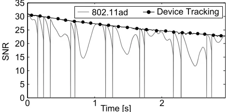
0 5 10 15 20 25 30 35
0 1 2
Time [s]
SNR
802.11ad Device Tracking
Figure 17: Example of the SNR fluctuations for one experi-ment in the PTP, large room, no obstacle scenario.
0 0.2 0.4 0.6 0.8 1 1.2 1.4 1.6 1.8
0 1000 2000 3000
0 5 10 15 2 25
Throughput (Mbps)
Device tracking
802.11ad
(a)
Throughput (Mbps)
Dev. tracking 802.11ad
(b)
x10-3
1000 2000 3000
x10-3
0
Figure 18: Throughput PDF of (a) PTP and (b) AP scenarios for a large room with no obstacles. 100 repetitions.
PTP AP
0 200
400 No Obst., Large Room
Out
ag
es
Two Obst. Self-Block. 0
200
400 AP, Small Room 802.11ad Dev. tracking
0.35 0.65
(a) (b)
Blocked
Block.
Figure 19: Number of outages due to steering misalignment and/or blockage. The arrows in (a) show the values of the bars that are too small to be legible. The arrows in (b) indi-cate the fraction of outage which occurs because of no work-ing (reflected) path bework-ing available due to the blockage.
our system is only affected by blockage outages, whereas 802.11ad additionally suffers from misalignment outages. Still, the gain is much smaller than for the case without obstacles. The reason is twofold. First, often no reflected path is available during a blockage. Thus, the outage cannot be avoided. Second, once blockage occurs, we often keep tracking the reflection even after the LOS is available again. Due to the robustness of Golay sequences, NLOS tracking continues even if the reflection is too weak for communication. That is, our tracking mechanismis too accurate. To address this, our mechanism can be paired with a LOS recovery approach.
Table 2: Average overhead and throughput stability of existing approaches for a 16-element antenna array
Mechanism Overhead1 σThroughput2 802.11ad Default [11, 22] 640µs
σ>1 Gbps Agile-Link [2] 385µs
BBS [33] 121µs
Reduced Search [36] 91µs Adaptive Search [37] 70µs
MOCA [17] 20µs
802.11ad Tracking [22] 11.04µs
σ=0.32 Gbps
Our approach 0µs
4.3
Comparison to Existing Approaches
5
DISCUSSION
Accuracy.Our evaluation shows that our device tracking mecha-nism achieves very high robustness and accuracy in terms of AoA estimation. In Section 4.2.3, we observe that for the NLOS case this can even result in sub-optimal performance in terms of through-put. This highlights the difference among pathdiscoveryand path maintenance. While both issues are often tackled using similar tech-niques (c.f. Section 6), our work shows that each is a topic on its own. As a result, accurate AoA estimation is not necessarily a syn-onym of high throughput. We conclude that our work is a perfect complement to existing approaches that excel at finding new paths when the current path becomes unavailable [48].
Cross-Layer Effects.Further, we observe that taking into ac-count not only the physical layer but also the link, network, and transport layers is crucial to fully understand the impact on perfor-mance of the characteristics of 60 GHz communication. Beyond the influence of TCP dynamics discussed in Section 4, rate adaptation at the link layer also plays a crucial role. We evaluated our system for the worst-case, that is, for a perfect rate adaptation algorithm that always chooses the optimal MCS and thus mitigates the impact of the high SNR fluctuations of 802.11ad. To avoid rate adaptation errors resulting in high packet losses, maintaining a stable SNR is crucial. Our approach tackles this problem extremely well.
Multi-User Scenarios.A natural question arising from our de-sign is how it performs in case of multiple users. Similarly to the 802.11ad protocol itself, our mechanism discards AoA estimations obtained from frames which are not addressed to the current node. While a receiver could receive higher interference due to the wider shape of the two-lobe beam pattern, this does not affect the data part of the packet, which is still received via the one-lobe beam pat-tern. To fully avoid this type of interference, nodes could perform clear channel assessment using the two-lobe beam pattern.
Future Work.The next steps of our device tracking approach include the integration with techniques to recover the LOS path after a blockage, the design of more accurate beam patterns when steering towards the edge of a phased array in practical deploy-ments, and the improved filtering of AoA estimates based on typical human movement to better identify outliers due to measurement errors. Further, we consider extending our scheme to 3D.
6
RELATED WORK
Device Tracking.Earlier work uses 60 GHz communication for object tracking following a radar-based approach [25, 56]. However, this requires nodes to simultaneously transmit and receive to, for example, track hand gestures or a pen. In contrast, we aim at track-ing an independent transmitter, and operate our mechanism at the receiver side only. Other approaches use external radars in the 60 GHz band to track the movement of objects [4, 45]. Our work stands apart from such schemes since our approach does not require any additional devices and is backward compatible with 802.11ad.
AoA Estimation.Similarly to related work, our mechanism tracks changes in the AoA [15, 55, 57]. The key difference to our approach is that we only compute relative changes, which simplifies our design significantly and allows us to operate with a single receive chain. Moreover, our mechanism does not need to resort to lower frequency bands for AoA estimation such as [33, 38].
Efficient Steering.Instead of using complex AoA estimation techniques, a large body of work focuses on sector-level accuracy, improving on the techniques standardized in 802.11ad [22]. To this end, such approaches often resort to beaconing on different sec-tors to determine the approximate angle to the receiver [21, 54]. This includes transmitting beacons on multi-lobe beam patterns, using beam patterns with random phase shifts for compressive sensing based tracking [2, 28, 41], or collecting historic information to reduce the duration of the beam-sweep [36, 37]. Still, in contrast to our work such approaches still incur training overhead. Other approaches use hybrid beam-forming to receive beacons from multi-ple directions simultaneously [35]. This requires a commulti-plex antenna design as well as multiple receiver chains, while we operate with a regular analog beam-forming antenna.
Hardware Validation.A key challenge in 60 GHz research is validating that mechanisms work in practice. Related work builds hardware for this purpose [1, 3, 58, 59] but typically does not achieve the full bandwidth of 802.11ad and uses antenna arrays with a limited number of elements. As a result, researchers often must resort to mimicking the behavior of 60 GHz radios using horn antennas. While this does provide fundamental insights into the performance of a mechanism, it cannot fully capture how it would operate on actual 60 GHz COTS hardware. In contrast, we validate our approach on a full-bandwidth system with a highly flexible phased antenna array. This allows us to get deep insights into our mechanism which otherwise would not be feasible.
7
CONCLUSION
Tracking mobile devices in 60 GHz networks is challenging but crucial to prevent harmful beam pattern misalignments. Existing ap-proaches to maintain alignment typically resort to periodic probing of adjacent beam patterns to keep track of the rotation and/or move-ment of a device, and thus incur significant overhead. In contrast, we present a device tracking mechanism that accurately tracks both rotation and movement of a device without incurring any overhead. The key idea is to receive part of the preamble of each packet via a custom two-lobe beam pattern. One of the lobes introduces a phase shift of 180◦. This allows the receiver to identify via which
lobe it received the preamble, and thus estimate its relative rotation towards the transmitter. We implement our mechanism in practice using a full-bandwidth IEEE 802.11ad setup with an electronically steerable phased antenna array. We also perform a simulation cam-paign in a broad range of scenarios. We show that our mechanism can reduce the steering error to below 5◦and achieves up to 2×
throughput gain. The mechanism becomes even more beneficial for future phased antenna arrays with higher number of antenna elements and narrower beam widths.
ACKNOWLEDGMENTS
REFERENCES
[1] Omid Abari, Haitham Hassanieh, Michael Rodreguiz, and Dina Katabi. 2016. Poster: A Millimeter Wave Software Defined Radio Platform with Phased Arrays. InProceedings of the 22Nd Annual International Conference on Mobile Computing and Networking.
[2] Omid Abari, Haitham Hassanieh, Michael Rodriguez, and Dina Katabi. 2016. Millimeter Wave Communications: From Point-to-Point Links to Agile Network Connections. InProceedings of the 15th ACM Workshop on Hot Topics in Networks.
[3] Julian Arnold, Ljiljana Simic, Marina Petrova, and Petri Mähönen. 2015. Demo: Spectrum-Agile mm-Wave Packet Radio Implementation on USRPs. InProceedings of the 2015 Workshop on Software Radio Implementation Forum.
[4] Julian Arnold, Ljiljana Simić, Marina Petrova, and Petri Mähönen. 2016. Radar-enhanced Mm-wave Agile Beamsteering: Demo. InProceedings of the Tenth ACM International Workshop on Wireless Network Testbeds, Experimental Evaluation, and Characterization.
[5] David Arthur and Sergei Vassilvitskii. 2007. K-means++: The Advantages of Careful Seeding. InProceedings of the Eighteenth Annual ACM-SIAM Symposium on Discrete Algorithms (SODA’07).
[6] Hany Assasa and Joerg Widmer. 2016. Implementation and Evaluation of a WLAN IEEE 802.11Ad Model in Ns-3. InProceedings of the Workshop on Ns-3. [7] Hany Assasa and Joerg Widmer. 2017. Extending the IEEE 802.11ad Model:
Scheduled Access, Spatial Reuse, Clustering, and Relaying. InProceedings of the Workshop on ns-3.
[8] R. Bonjour, M. Burla, F. C. Abrecht, S. Welschen, C. Hoessbacher, W. Heni, S. A. Gebrewold, B. Baeuerle, A. Josten, Y. Salamin, C. Haffner, P. V. Johnston, D. L. Elder, P. Leuchtmann, D. Hillerkuss, Y. Fedoryshyn, L. R. Dalton, C. Hafner, and J. Leuthold. 2016. Plasmonic phased array feeder enabling symbol-by-symbol mm-wave beam steering at 60 GHz. In2016 IEEE International Topical Meeting on Microwave Photonics (MWP).
[9] R. Bonjour, M. Singleton, S. A. Gebrewold, Y. Salamin, F. C. Abrecht, B. Baeuerle, A. Josten, P. Leuchtmann, C. Hafner, and J. Leuthold. 2016. Ultra-Fast Millimeter Wave Beam Steering.IEEE Journal of Quantum Electronics52, 1 (2016).
[10] J. Canilho, M. Véstias, and H. Neto. 2016. Multi-core for K-means clustering on FPGA. InProceedings of the 26th International Conference on Field Programmable Logic and Applications (FPL).
[11] Alecsander Eitan and Carlos Cordeiro. 2016.Short SSW Format for 11ay (IEEE 802.11-16/0416-01-00).
[12] Maya Erez and Kalle Valo. 2017. Low Level RF Sector API for Wil6210 Driver. https://patchwork.kernel.org/patch/9726747/. (2017).
[13] Mike Estlick, Miriam Leeser, James Theiler, and John J. Szymanski. 2001. Al-gorithmic Transformations in the Implementation of K- Means Clustering on Reconfigurable Hardware. InProceedings of the 2001 ACM/SIGDA Ninth Interna-tional Symposium on Field Programmable Gate Arrays.
[14] M. Golay. 1961. Complementary series.IRE Transactions on Information Theory
7, 2 (1961).
[15] Frank Gross. 2005.Smart Antennas for Wireless Communications. McGraw-Hill Professional.
[16] Sangtae Ha, Injong Rhee, and Lisong Xu. 2008. CUBIC: A New TCP-friendly High-speed TCP Variant.SIGOPS Oper. Syst. Rev.42, 5 (2008).
[17] Muhammad Kumail Haider and Edward W. Knightly. 2016. Mobility Resilience and Overhead Constrained Adaptation in Directional 60 GHz WLANs: Protocol Design and System Implementation. InProceedings of the 17th ACM International Symposium on Mobile Ad Hoc Networking and Computing (MobiHoc).
[18] Daniel Halperin, Srikanth Kandula, Jitendra Padhye, Paramvir Bahl, and David Wetherall. 2011. Augmenting Data Center Networks with Multi-gigabit Wireless Links. InProceedings of the ACM SIGCOMM 2011 Conference.
[19] Christian Hennig. 2007. Cluster-wise assessment of cluster stability. Computa-tional Statistics and Data Analysis(2007), 258–271.
[20] Christian Hennig. 2008. Dissolution point and isolation robustness: Robustness criteria for general cluster analysis methods.Journal of Multivariate Analysis99,
6 (2008).
[21] K. Hosoya, N. Prasad, K. Ramachandran, N. Orihashi, S. Kishimoto, S. Rangarajan, and K. Maruhashi. 2015. Multiple Sector ID Capture (MIDC): A Novel Beam-forming Technique for 60-GHz Band Multi-Gbps WLAN/PAN Systems.IEEE Transactions on Antennas and Propagation63, 1 (2015).
[22] IEEE. 2012. Wireless LAN Medium Access Control (MAC) and Physical Layer (PHY) Specifications Amendment 3: Enhancements for Very High Throughput in the 60 GHz Band.IEEE Std 802.11ad-2012(2012).
[23] IMEC International. 2016. PHARA4 Antenna Module. https://www.imec-int. com/en/mmwave-wireless-communication. (2016).
[24] R.E. Kalman. 1960. A New Approach to Linear Filtering and Prediction Problems.
ASME Journal of Basic Engineering82, 1 (1960).
[25] Jaime Lien, Nicholas Gillian, M. Emre Karagozler, Patrick Amihood, Carsten Schwesig, Erik Olson, Hakim Raja, and Ivan Poupyrev. 2016. Soli: Ubiquitous Gesture Sensing with Millimeter Wave Radar.ACM Trans. Graph.35, 4 (July
2016).
[26] Alexander Maltsev. 2010.Channel Models for 60 GHz WLAN Systems (IEEE 802.11-09/0334r8).
[27] G. Mangraviti, K. Khalaf, Q. Shi, K. Vaesen, D. Guermandi, V. Giannini, S. Brebels, F. Frazzica, A. Bourdoux, C. Soens, W. Van Thillo, and P. Wambacq. 2016. 13.5 A 4-antenna-path beamforming transceiver for 60GHz multi-Gb/s communication in 28nm CMOS. In2016 IEEE International Solid-State Circuits Conference (ISSCC).
[28] Z. Marzi, D. Ramasamy, and U. Madhow. 2016. Compressive Channel Estimation and Tracking for Large Arrays in mm-Wave Picocells.IEEE Journal of Selected Topics in Signal Processing10, 3 (2016).
[29] A.E. Minetti. 2000. The Three Modes of Terrestrial Locomotion. InBiomechanics and Biology of Movement, Joachim Mester Benno Maurus Nigg, Brian R. MacIntosh
(Ed.). Human Kinetics.
[30] Prem Nerella. 2014. IEEE 802.11ad PHY Waveform Generation API. (2014). [31] Ernst Neufert. 1970.Architects’ Data. Lockwood.
[32] Thomas Nitsche, Guillermo Bielsa, Irene Tejado, Adrian Loch, and Joerg Widmer. 2015. Boon and Bane of 60 GHz Networks: Practical Insights into Beamforming, Interference, and Frame Level Operation. InProc. of CoNEXT’15.
[33] T. Nitsche, A. B. Flores, E. W. Knightly, and J. Widmer. 2015. Steering with eyes closed: Mm-Wave beam steering without in-band measurement. In2015 IEEE Conference on Computer Communications (INFOCOM).
[34] Sophocles J. Orfanidis. 2016.Electromagnetic Waves and Antennas.
[35] J. Palacios, D. De Donno, D. Giustiniano, and J. Widmer. 2016. Speeding up mmWave beam training through low-complexity hybrid transceivers. In2016 IEEE 27th Annual International Symposium on Personal, Indoor, and Mobile Radio Communications (PIMRC). 1–7.
[36] Avishek Patra, Ljiljana Simić, and Petri Mähönen. 2015. Smart mm-Wave Beam Steering Algorithm for Fast Link Re-Establishment Under Node Mobility in 60 GHz Indoor WLANs. InProceedings of the 13th ACM International Symposium on Mobility Management and Wireless Access (MobiWac ’15).
[37] A. Patra, L. Simic, and M. Petrova. 2016. Experimental evaluation of a novel fast beamsteering algorithm for link re-establishment in mm-wave indoor WLANs. In2016 IEEE 27th Annual International Symposium on Personal, Indoor, and Mobile Radio Communications (PIMRC). 1–7.
[38] A. Patra, L. Simić, and M. Petrova. 2017. Design and experimental evaluation of a 2.4 GHz-AoA-enhanced beamsteering algorithm for IEEE 802.11ad mm-wave WLANs. In2017 IEEE 18th International Symposium on A World of Wireless, Mobile and Multimedia Networks (WoWMoM).
[39] Qualcomm. 2017. Linux Wil6210 Driver. https://github.com/torvalds/linux/tree/ master/drivers/net/wireless/ath/wil6210. (2017).
[40] T. S. Rappaport, S. Sun, R. Mayzus, H. Zhao, Y. Azar, K. Wang, G. N. Wong, J. K. Schulz, M. Samimi, and F. Gutierrez. 2013. Millimeter Wave Mobile Communica-tions for 5G Cellular: It Will Work!IEEE Access1 (2013).
[41] Maryam Eslami Rasekh, Zhinus Marzi, Yanzi Zhu, Upamanyu Madhow, and Haitao Zheng. 2017. Noncoherent mmWave Path Tracking. InProceedings of the 18th International Workshop on Mobile Computing Systems and Applications. [42] George F. Riley and Thomas R. Henderson. 2010.The ns-3 Network Simulator.
Springer Berlin Heidelberg, 15–34.
[43] S. K. Saha, V. V. Vira, A. Garg, A. Tennenbaum, and D. Koutsonikolas. 2015. On the feasibility of indoor IEEE 802.11ad WLANs. In2015 IEEE Conference on Computer Communications Workshops (INFOCOM WKSHPS).
[44] M. Shoaib, S. Bosch, O.D. Incel, H. Scholten, and P.J.M. Havinga. 2014. Fusion of Smartphone Motion Sensors for Physical Activity Recognition.Sensors14 (2014),
10146–10176.
[45] Ljiljana Simić, Julian Arnold, Marina Petrova, and Petri Mähänen. 2016. RadMAC: Radar-enabled Link Obstruction Avoidance for Agile Mm-wave Beamsteering. In
Proceedings of the 3rd Workshop on Hot Topics in Wireless.
[46] D. Steinmetzer, J. Classen, and M. Hollick. 2016. mmTrace: Modeling millimeter-wave indoor propagation with image-based ray-tracing. In2016 IEEE Conference on Computer Communications Workshops (INFOCOM WKSHPS).
[47] Sanjib Sur, Vignesh Venkateswaran, Xinyu Zhang, and Parmesh Ramanathan. 2015. 60 GHz Indoor Networking Through Flexible Beams: A Link-Level Pro-filing. InProceedings of the 2015 ACM SIGMETRICS International Conference on Measurement and Modeling of Computer Systems.
[48] Sanjib Sur, Xinyu Zhang, Parmesh Ramanathan, and Ranveer Chandra. 2016. BeamSpy: Enabling Robust 60 GHz Links Under Blockage. In13th USENIX Sym-posium on Networked Systems Design and Implementation (NSDI 16).
[49] Hajime Tazaki, Frédéric Uarbani, Emilio Mancini, Mathieu Lacage, Daniel Camara, Thierry Turletti, and Walid Dabbous. 2013. Direct Code Execution: Revisiting Library OS Architecture for Reproducible Network Experiments. InProceedings of the Ninth ACM Conference on Emerging Networking Experiments and Technologies (CoNEXT’13).
[50] Robert Tibshirani, Guenther Walther, and Trevor Hastie. 2001. Estimating the number of clusters in a data set via the gap statistic.Journal of the Royal Statistical Society: Series B (Statistical Methodology)63, 2 (2001).
[52] Y. M. Tsang, A. S. Y. Poon, and S. Addepalli. 2011. Coding the Beams: Improving Beamforming Training in mmWave Communication System. In2011 IEEE Global Telecommunications Conference - GLOBECOM 2011.
[53] Alberto Valdes-Garcia, Sean T. Nicolson, Jie-Wei Lai, Arun Natarajan, Ping-Yu Chen, Scott K. Reynolds, Jing-Hong Conan Zhan, Dong G. Kam, Duixian Liu, , and Brian Floyd. 2010. A fully integrated 16-element phased-array transmitter in SiGe BiCMOS for 60-GHz communications.IEEE Journal of Solid-State Circuits
45, 12 (2010).
[54] J. Wang. 2009. Beam codebook based beamforming protocol for multi-Gbps millimeter-wave WPAN systems.IEEE Journal on Selected Areas in Communica-tions27, 8 (2009).
[55] Ju Wang, Jie Xiong, Hongbo Jiang, Xiaojiang Chen, and Dingyi Fang. 2016. D-Watch: Embracing "Bad" Multipaths for Device-Free Localization with COTS RFID Devices. InProceedings of the 12th International on Conference on Emerging Networking EXperiments and Technologies.
[56] Teng Wei and Xinyu Zhang. 2015. mTrack: High-Precision Passive Tracking Using Millimeter Wave Radios. InProceedings of the 21st Annual International Conference on Mobile Computing and Networking.
[57] Jie Xiong and Kyle Jamieson. 2013. ArrayTrack: A Fine-grained Indoor Location System. InProceedings of the 10th USENIX Conference on Networked Systems Design and Implementation.
[58] P. Zetterberg and R. Fardi. 2015. Open Source SDR Frontend and Measurements for 60-GHz Wireless Experimentation.IEEE Access(2015).
[59] Jialiang Zhang, Xinyu Zhang, Pushkar Kulkarni, and Parameswaran Ramanathan. 2016. OpenMili: A 60 GHz Software Radio with a Programmable Phased-array Antenna: Demo. InProceedings of the 22Nd Annual International Conference on Mobile Computing and Networking.