GLOBAL JOURNAL OF ADVANCED ENGINEERING TECHNOLOGIES AND
SCIENCES
FORKED MOVING CONTACTS IN POWER CIRCUIT BREAKERS: SOLUTION
TO CONSTANT POWER LOSSES INCURRED IN THE USE OF SERIES
SHORT-CIRCUIT CURRENT LIMITING REACTORS ON FEEDERS
Akpeh V.A*, Echedom V.C
*
Transmission Company of Nigeria (TCN)
ABSTRACT
This paper develops a novel strategy for mitigating the limitations in the use of series short circuit Current Limiting Reactor (CLR) on feeders. The methodology involves the use of forked moving contacts for parallel operation of short circuit Current Limiting Reactor and current conducting bars similar to, but better than both the parallel operation of IS- Limiter and Current limiting reactor and the Improved IS- Limiter Technique for implementing fault current limiting reactors on feeders at no constant power losses [1,2].
KEYWORDS: Current limiting reactor, Fixed contact, Forked moving contact, IS- Limiter, Parallel operation, short-circuit current.
INTRODUCTION
The use of straight moving contact in power circuit breakers does not much help matters in the use of series current limiting reactors for short circuit current limitation. Though current limiting reactor (CLR) is the most practical technique for reducing short circuit currents to levels within the rating of the equipment on the load side of the reactor, their use is limited to some critical feeders due to the constant power losses caused by them since they are connected in series with the feeders and as such carry the full load current [3, 4, 5].
Solution to the above problem is achieved by modifications in the fixed and moving contacts [6]. However, the behavior of the length, cross-sectional area, volume and the mass of the moving contact rod and their implication on the operating mechanism energy requirements and costs of the power circuit breaker are of great interest.
PARALLEL OPERATION OF CURRENT LIMITING REACTOR AND I
S- LIMITER
IS-LIMITERS AND REACTORS CONNECTED IN PARALLEL
If system components are not to be totally isolated in the case of a short circuit, but further supplied via a short-circuit current limiting reactor, the reactor can be bridged by an Is-limiter in normal operation, so as to avoid the copper losses, voltage fluctuations which would otherwise occur during load changes and the electro-magnetic influences causes by each reactor [1, 7]. Figure 1 shows Is-limiter and reactors connected in parallel in both incoming and outgoing feeder [8].
Figure 1: Is-limiter and reactors connected in parallel
LIMITATIONS OF THE IS-LIMITER AND REACTORS CONNECTED IN PARALLEL
The following limitations are encountered here: (a) Its use is still limited to 40kV rated voltage
(b) Constant power losses is encountered after the operation of the Is-limiter since the system components are not to be totally isolated in the case of a short circuit.
(c) Restoring the normal operation of the arrangement involves reasonable equipment down time especially in the event of transient faults.
THE IMPROVED IS – LIMITER.
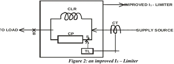
The improved IS – limiter as shown in figure 2 is simply a parallel arrangement of a Current Limiting Reactor (CLR) and a Copper conducting path (CP) with a fast operating isolator, S [2]. At normal system condition, the current limiting reactor is shorted out by the copper conducting path. When short-circuit occurs, isolation of the copper conducting path is triggered by the Triggering Logic system (TL). This must be done before the first half cycle is reached.
X
__________
__________
__________
________
__
___
___
___
_
__________
<
<
<
>
SUPPLY SOUR CE CT
CLR
CP
TL S B
TO LOAD
IMPROVED I - LI MITERS
Figure 2: an improved IS – Limiter
LIMITATIONS OF THE IMPROVED IS – LIMITER
The limitation here lies in the speed at which the opening of the isolator, S, starts. There is no problem if reasonable speed is achieved.
THE CIRCUIT BREAKER (CB) COMPONENTS
The CBs are essential components of the entire HV switchgear portfolio. CBs consist of the interrupter unit, post insulator, control system, operating mechanism and the base frame (pillar) [9, 10].
At the top of the interrupter unit as well as the junction of the interrupter unit and the post insulator are terminals where the power line enters/leaves the CB. In other words, the CB is always in series with the feeder such that the choice of most engineers installing it in the utility company had been to connect the load to the upper terminal and the supply source to the lower terminal, or vice versa, based on some peculiarities on ground the [11]. The terminals on the interrupter unit/post insulator are shown in figure 3.
Terminal
Terminal Interrupter unit
Post insulator
Figure 3: Post Insulator/Interrupter unit of a CB MODIFICATIONS ON THE CB
MODIFICATIONS ON THE CB INTERRUPTER UNIT (A) THE CB TERMINALS:
To achieve our aim, the load must always be connected on the lower terminal. The upper terminal is split into two and separated for:
(1) Connecting the CLR and (2) Connecting the CLR bypass bar. This is shown in figure 4.
Terminal
Terminal
Interrupter unit
Post insulator
(a)
CLR Terminal
Insulator
Interrupter unit
Terminal
Post insulator
CLR bypassterminal
(b)
Figure 4: Post Insulator/Interrupter unit of a CB showing (a) existing and, (b) recommended modification.
(B) THE FIXED CONTACT:
The fixed contact is split into two and separated for connecting: (1) The CLR and
Fixed contact
for CLR bypass
Fixed contact
for CLR
Figure 5: Fixed contacts
MODIFYING THE STRAIGHT MOVING CONTACT ROD OF CIRCUIT BREAKERS TO TWO PRONGED FORKED MOVING CNTACT
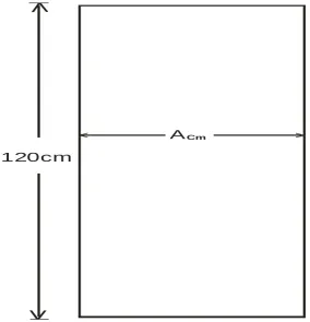
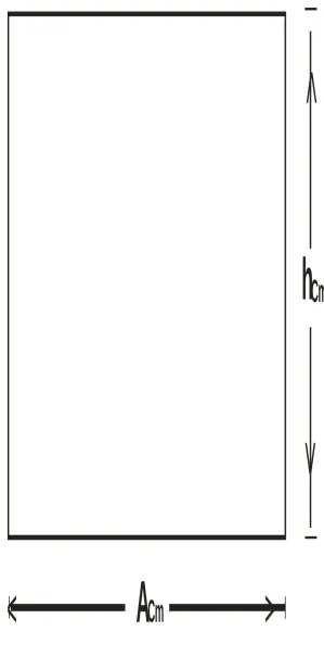
The modification is done with a 132kV straight moving contact rod of length equal to 120cm. A square cross-section is used for the rod in this study. A straight moving contact of square cross-cross-section of a side equal to A centimetres is shown in figure 6.
> <
>
>
120cm
A
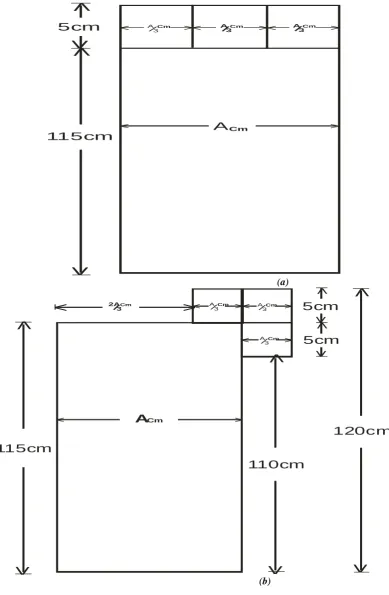
Cm5cm length is measured from the top of the straight moving contact and split into three equal parts as shown in figure 7(a). Two parts are moved to the right and arranged as shown in figure 7(b). The process is repeated on the left with the same dimensions of same material cut from similar rod but this time with 1cm (10mm) reduction in length (height) as shown in figure 7(c). The aim for this reduction in the length (height) as seen in figure 7(c) is to get prongs of unequal lengths – a difference in lengths of 1cm (i.e. 10mm) as shown in figure 7(d).
>
> > >
<
< < <
>
>
>
>
5cm
115cm
A
CmA/3Cm A/
3Cm A/3Cm
(a)
>
>
> >
<
<
< <
>
>
>
>
>
>
>
>
>
>
115cm
110cm
120cm
A
Cm5cm
5cm
A/ 3Cm A/
3Cm A/
3Cm
>
<
2A/3Cm
> > > > >< < < < <
>
>
>
>
>
>
>
>
119cm 110cmA Cm
2 A/
3Cm
A/
3Cm A/3Cm
A/ 3Cm 4cm 5cm (c) (d) Figure 7: Design of forked moving contact
With the help of figure 7(a), it can be seen that figures 6, 7(a) and 7(b) are equal in terms of effective area, volume and even mass, being made of the same material.
From figure 7(d), the length (height) of the rod when considering the space available for it in the circuit breaker interrupter unit is still the same as that for the straight moving contact shown in figure 6, but in the real sense of it, the overall length (height) of the forked moving contact has increased by the shorter prong detached and shown in figure 8.
119cm > > > < < <
>
>
>
>
>
>
>
>
120cm9 c m 10cm
2A
/
3
Cm
2A
/
3
Cm
A Cm
119cm > > > < < <
>
>
>
>
>
>
>
>
120cm9 c m 10cm
2A
/
3
Cm
2A
/
3
Cm
A Cm
> < A/
>
>
>
>
> <
> <
2A/
3Cm
9cm
A/ 3C m
4cm
Figure 8: Added length on the forked moving contact
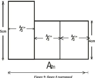
With the aid of figure 7(a), figure 8 can be rearranged as shown in figure 9.
>
>
>
>
>
>
>
<
<
<
>
<
5cm
A
Cm
A
/
3
CmA
/
3
Cm
A
/
3
Cm4cm
Figure 9: figure 8 rearranged
The uniform length (height) of figure 9 can be calculated with the aid of figure 10 whose area is equivalent to that of figure 9, thus:
(5 𝑋 𝐴
3 + 4 𝑋 2𝐴
3 ) cm
2 = ( h x A)cm2
OR 13𝐴
3 cm
2 = (h x A)cm2
OR
h = 4.33
>
<
>
>
A
Cm
h
Cm
Figure 10: Equivalent area of figure 9.
THE FORKED MOVING CONTACT:
Forked moving contact
Figure 11: Forked moving contact
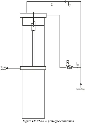
Figure 12: CLR/CB prototype connection
Legend to figure 12 R = the CLR
C = the CLR bypass bar
IR = the current through the CLR
IC = the current through the CLR bypass bar.
EFFECTS OF RATED SHORT-CIRCUIT BREAKING CURRENTS ON THE OPERATING
MECHANISM ENERGY REQUIREMENTS OF A POWER CIRCUIT BREAKER.
THE BLAST PRESSURE ∆P, AND THE RATED SHORT-CIRCUIT BREAKING CURRENT
The rated short-circuit breaking current i, exercises its influence on the required operating mechanism energy mainly through the blast pressure ∆P which is necessary to warrant reliable arc-quenching under short-line fault conditions. Experimental results show the relationship between the required blast pressure ∆P and the current
slope 𝑑𝑖
𝑑𝑡 as:
∆P ∝ [𝑑𝑖
𝑑𝑡]
a (1)
Where:
The constant ‘a’ assumes a value between 1.1 and 1.42, depending on the filling pressure Po in the circuit breaker [12].
However, as already confirmed by many authors, blast pressure ∆P can be reduced by increasing the number of breaks N. With the well known relationship between current slope 𝑑𝑖
𝑑𝑡 and the rate of rise of re-striking voltage
(RRRV),𝑑𝑣
𝑑𝑡,
<
<
>
C
C
R
R
I
I
Supply Source
𝑑𝑣 𝑑𝑡 . [
𝑑𝑖 𝑑𝑡]
n = constant (2)
With large varying values between 1 and 7 as is always the case, specified for n, the effect of N on ∆P can be obtained as follows:
∆P ∝ ia. N-a/n (3)
If a value of 1.4 is substituted for ‘a’ and a value of 5 for ‘n’ in equation (3), the following results:
∆P ∝ i1.4. N-0.28 (4)
Equation (4) gives the response curve shown in figure 13.
Figure 13: Response curve of blast pressure against fault current
THE PISTON AREA, A, THE RATED SHORT-CIRCUIT BREAKING CURRENT
The rated short circuit breaking current also has effect in the required blast volume, or if the contact stroke is not modified, the piston area, A, will be influenced because the nozzle cross-section has to be adapted to the arc cross-section AA. As a first approximation, the following relationship can be assumed [12]:
A ∝ AA ∝ 𝑖
√P (5)
As the pressure P = P0 + ∆P depends again on the current, the dependence of the nozzle cross-section and the Piston area on current is less than one would expect. For large blast pressure, ∆P is much greater than P0, i.e.
∆P >> P0 And thus,
P ≈ ∆P Where
P = pressure A = piston area ∆P = blast pressure P0 = filling pressure AA = arc cross-section
Substituting equation (4) in (5) gives
A ∝ 𝑖
√(𝑖1.4.𝑁−0.28) This implies
A ∝ 𝑖
𝑖0.7.𝑁−0.14 i.e.
A ∝ i x i-0.7 x N0.14 Or
A ∝ i0.3 x N0.14 (6)
Equation (6) results in the response curve shown in figure 14.
100 150 200 250 300 350 400 450 500 550
20 30 40 50 60 70 80 90 100
BLAST PRESSURE [kg/cm2]
Figure 14: Response curve of the moving contact area against the fault current
THE BLAST PRESSURE ∆P AND COMPRESSION WORK, WCOMP
The relationship between blast pressure ∆P and compression work, Wcomp, is not simple since one part of the blast pressure is produced by the arc through heating up. Assuming a linear relationship as a rough approximation [12], ∆P relates with the compression work, WCOMP thus:
WCOMP ∝ N.A. ∆P (7)
But
√𝑃 ∝ 𝑖
𝐴
And
P = P0 + ∆P (8)
But for large blast pressure: ∆P ≫ P0 and so P ≈ ∆P. From equation (6),
A ∝ i0.3.N0.14
Substituting equations (4) and (6) in equation (7) gives:
WCOMP ∝ N.i0.3.N0.14.i1.4.N-0.28 OR
WCOMP ∝ N0.86.i1.7 (9)
Equation (9) results in the response curve shown in figure 15.
Figure 15: Response curve of compression work against fault current
3 3.5 4 4.5
30 40 50 60 70 80 90 100
AREA[cm2]
F au lt cu rr en t[ kA ]
0.5 1 1.5 2 2.5 3 3.5 4 4.5
30 40 50 60 70 80 90 100
COMPRESSION WORK[kilo Newtons]
THE EFFECT OF THE OVERALL LENGTH OF THE FORKED MOVING CONTACT ON
ITS MASS
The mass of the copper moving contact, M, is the product of its volume, V, and the density, d. i.e. M = d x V But
V = h x A Where
h = the height (i.e. the length) of the moving contact and A = the cross sectional area of the moving contact. But from equation (6),
A ∝ i0.3 x N0.14 Such that:
M = d x h x i0.3 x N0.14 (10)
From equation (10), the effect of the increased overall length (height) of the forked moving contact rod on its mass is shown in the response curves given in figure 16.
Figure 16: Response curve of the overall mass of the forked moving contact against the fault current.
DISCUSIONS
CLR CONNECTIONFrom figures 12, (CB in closed position), the reactance of the CLR, ‘XR’, is parallel to the reactance of the CLR bypass bar, ‘XC’, i.e.
XR // XC).
With XR >> XC, the equivalent reactance, ‘Xeq’, of the circuit is less than XC. This implies that no power losses are encountered under parallel connection of R and C in the circuit.
Also, with XR >> XC, the CLR could be shorted out by the bypass bar ‘C’, under parallel arrangement of ‘R’ and ‘C’ in the circuit. This again is a desirable result as no constant power losses is recorded at normal system condition.
3400 3600 3800 4000 4200 4400 4600 4800
30 40 50 60 70 80 90 100 110 120
MASS[kg]
F
a
u
lt
c
u
rr
e
n
t[
k
A
]
NO CLR used on straight moving contact
BRINGING THE CLR IN SERIES WITH THE FEEDER DURING CB OPENING/CLOSING
During CB opening, the shorter prong of the forked moving contact rod breaks contact with the CLR bypass bar while the longer prong is yet to break contact with the CLR. Instantaneously, there shall be current reversal in the CLR/CLR-bypass bar junction [6], thereby bringing the CLR in series with the feeder just before the breaker contacts begin to open.
During CB closing, the CLR is serially connected in the circuit while the shorter prong is yet to make contact with the CLR bypass bar. As soon as the CB closing operation is completed, by current reversal again at the CLR/CLR-bypass bar junction, the CLR becomes shorted out by the bypass bar.
Based on the above discussion, it is seen that the CB always opens (whether during fault or not) with the CLR in series but the CLR is shorted out when CB is closed. This is a desired result. Also, should the CB be closed on to a fault, there shall be no cause for alarm even if the protection is so fast that it opens the CB before it is completely closed.
FORKED MOVING CONTACT MASS
When the moving contact is forked, the overall length (height) is slightly increased. From the expression:
Mass = volume (i.e. area x height) x density,it appears there could be increased mass and as such increased operating mechanism energy but as shown in equations (6), (7) and (9), reducing the current reduces the cross-sectional area of the moving contact rod and the compression work, ‘WCOMP’. That is, the mass of the moving contact rod is reduced even though the height is slightly increased as can be seen in the response curve of the moving contact area against the fault current, for the values of ‘I’ between 35.7kA and 98.7kA and for number of breaks, ‘N’ = 2, shown in figure 14.
This is clearly seen in the response curve of fault current reduction against the overall mass of the forked moving contact rod of the CB (overall length = 124.33cm) compared with the mass of the required (straight) moving contact rod (length = 120cm) when no CLR is used, shown in figure 16.
However, it should be noted from figure 16 that the fault current must be reduced below a certain limit (the efficiency threshold) before the mass of the rod begins to decrease else, the mass is higher.
CONCLUSIONS
The strategy for mitigating the limitations in the use of straight moving contacts in power circuit breakers has been presented in this paper. With this, the use of series short circuit Current Limiting Reactors are no longer limited to critical feeders but can be used on all feeders as the need arises.
REFERENCES
[1] Brandt, A., Hartung, K.-H., Bockholt, R. and Schmidt, V. (2010). Is-limiter: Limitation of short-circuit currents for maximum economic benefits. Germany: ABB AG - 40472 Ratingen. 1- 4.
[2] AKPEH, V.A. and OMINI, G.U. (2017). Improved Is – Limiter Technique for Implementing Fault Current Limiting Reactors on Feeders at no Constant Power Losses. India: International Journal of Engineering Sciences & Research Technology 6, (4), 1- 4.
[3] www.trenchgroup.com. Current Limiting & Power Flow Control Reactors – Air Core Reactors. Trench Group 2014. Retrieved 1st August, 2014.
[4] en.wikipedia.org/wiki/current_limiting_reactor. Current Limiting Reactor – Wikipedia, The Free Encyclopedia. Retrieved 1st August 2014.
[5] Gupta, B.R. (2012). Generation of Electrical Energy. New Delhi: Eurasia Publishing House (P) Ltd. [6] Akpeh, V.A., Madueme, T.C., Ezechukwu, O.A., Ogboh, V.C. and Echedom, V.C. (2015). A
Methodology for Implementing Fault Current Limiting Reactors (CLRs) on Feeders with Minimal Constant Power Losses. India: Global Journal of Engineering, Design & Technology. 4, (5), 1-7. [7] Dreimann, E., Grafe, V. and Hartung, K.H. (1994). Protective device for limiting short-circuit currents.
Germany: ABB AG 1, (15), 492-494.
[8] www07.abb.com/images/librariesprovider85/default-album/fig4_reactors_connected.
[9] Heinemann, L., Huanxin, C. and ABB AG (2014). Technology Benchmark of Operating Mechanisms for High Voltage Switchgear. Germany: ABB AG. 1-8.
[11]Akpeh, V.A., Madueme, T.C. and Ezechukwu, O.A. (2015). A new approach to Implementing Fault Current Limiting Reactors (CLRs) on Feeders with Negligible Constant Power losses. India: International Journal of Modern Engineering Research. 5, (11), 37-46.
![Figure 1: Is-limiter and reactors connected in parallel SOURCE: [www07.abb.com/images]](https://thumb-us.123doks.com/thumbv2/123dok_us/8683471.1734050/1.595.206.400.532.741/figure-limiter-reactors-connected-parallel-source-www-images.webp)