Performance evaluation of composite
marine propeller using L
8
orthogonal array
S.Solomon Raj 1 Dr.P.Ravinder Reddy 2
1. Assistant professor, department of mechanical engineering, chaitanya bharathi institute of technology, gandipet, Hyderabad-75. email: [email protected]
2. Professor and Head, department of mechanical engineering, chaitanya bharathi institute of technology, gandipet, Hyderabad-75. email: [email protected]
Abstract
This work aims at understanding the effect of various parameters on the performance of a marine propeller using L8 orthogonal array. The parameters chosen are advance velocity , rotational speed and the stacking
sequence . A four bladed composite propeller made of glass-epoxy is modelled using dynamic hydro-elastic scaling laws for marine propulsors and analyzed using the hydro-elastic model. An L8 orthogonal array is used
for understanding the effect of various parameters and their interaction effect on the performance of a marine propeller in terms of open water characteristics.
1. Introduction
cracking and has relatively poor acoustic damping properties that can lead to noise due to structural vibration. Moreover, composites can offer the potential benefits of reduced corrosion and cavitation damage, improved fatigue performance, lower noise, improved material damping properties, and reduced lifetime maintenance cost. In addition the load-bearing fibers can be aligned and stacked to reduce fluttering and to improve the hydrodynamic efficiency by automatically adjusting the shape of the blade [young 2001]. Lin (1991a, 1991b) analyzes by the finite element method a moderately skewed partial composite blade from a 0.21m diameter seven-blade propeller, and compares the results with an all-alloy blade of the same geometry. The stress computations are performed using three-dimensional solid finite elements, and strength checks are made based on the finite element results. The computed tip deflection of the composite blade is an order of magnitude larger than that of the isotropic alloy blade. The maximum in-plane bending and shearing stresses for the composite blade are approximately 50 percent greater than the all-alloy blade. Lin and Lin (1997) examine the effects of stacking sequences on the performance of a composite propeller using a coupled fluid-structure interaction method. A geometrically linear finite element procedure for the structural analysis is coupled with non-cavitating lifting surface theory for the fluid analysis. The finite element analysis uses a degenerate shell element with five degrees of freedom per node. The effects of stacking sequence on the thrust, torque, efficiency and deflections are examined for a 1.40m diameter three-blade carbon fibre and epoxy propeller. Model scale analysis remains the standard means of evaluating the performance of the prototype because of the cost and the configuration considerations. In this work, the prototype is scaled down using the dynamic hydro-elastic scaling laws for the flexible rotors. Then the model is analyzed using the fluid and structural analysis. The fluid analysis is carried out using the general purpose CFD software Fluent 6.3.26 and structural analysis is carried out using ANSYS11. With the increased use of fiber-reinforced composites in structural components, studies involving the behavior of such structures and their members are receiving considerable attention. This study is directed toward one such engineering application, i.e., the composite propeller. The objective of this research is to study numerically the behavior of a conventional propeller, made from composite material, under hydro-dynamic loading. Emphasis is placed on understanding the effects of various parameters on propeller performance.
1.1. Propeller performance
In general, the performance of a marine propeller is measured in-terms of open-water characteristics. The parameters used for this purpose are
;
;
;
;
2. Methodology
In this work, three parameters are considered for analysis. They are advance velocity Va, rotational speed N and the stacking sequence. For this purpose a four bladed prototype propeller having diameter 410mm is scaled down using hydro-dynamic scaling laws for shape-adoptive marine propulsors as shown in table 1. The scaling factor adopted here is 1/2. accordingly the parameters are evaluated for prototype and the model for Reynolds similarity. The fluid analysis is carried out using the general purpose CFD software Fluent 6.3.26 fairing caps and shaft are added to the propeller. The inlet was considered at a distance of 3D (where D is diameter of the propeller) from mid of the chord of the root section. Outlet is considered at a distance of 4D from same point at downstream. In radial direction domain was considered up to a distance of 4D from the axis of the hub. This peripheral plane is called far-field boundary. The mesh was generated in such a way that cell sizes near the blade wall were small and increased towards outer boundary. The pressure obtained from the above analysis is used as an input to the structural model using general purpose finite element software ANSYS 11.0 to get the deformed configuration. Fluid analysis is carried out again on the deformed configuration to obtain the new pressure distribution on the blades. This process is repeated till the convergence is achieved, i.e the difference is KQ between two consecutive iterations is less than 5%. The methodology adopted is as shown
in fig1.
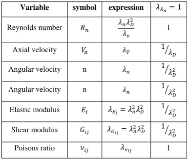
Table 1: scaling factors of different variables
Variable symbol expression 1
Reynolds number 1
Axial velocity 1
Angular velocity n 1
Angular velocity n 1
Elastic modulus 1
Shear modulus 1
Fig 1: Hydro-elastic model
3. Results and discussion
The analysis is carried out for three parameters at two levels using an L8 orthogonal array. The material
properties of glass-epoxy are shown in table 2 and the parameters and the values used are presented in table 3.
Table 2: Properties of glass-epoxy
Material properties Full model
E1 153 GPa
E2 10.9 GPa
G12 5.9 GPa
G13 5.9 GPa
ν 12 0.3
Table 3: L8 Array and the parameters
Run Va(m/sec) N(RPM) Stacking sequence
1 6.2 1100 S 1
2 6.2 1100 S 2
3 6.2 1500 S 1
4 6.2 1500 S 2
5 9.25 1100 S 1
6 9.25 1100 S 2
7 9.25 1500 S 1
8 9.25 1500 S 2
Where S 1 and S 2 consist of all glass-epoxy layers of 0.3mm thick and the stacking sequence is as shown.
start
Analyze the propeller in FLUENT
Obtain the pressure distribution
Map pressure to structural model
Obtain the deformed propeller shape
Convergenc
Table 4: effect of various parameters on KT
Run Va (m/sec) N(RPM) Va*N S Va*S N*S Va*N*S KT
1 1 1 1 1 1 1 1 0.094
2 1 1 1 2 2 2 2 0.22
3 1 2 2 1 1 2 2 0.222
4 1 2 2 2 2 1 1 0.243
5 2 1 2 1 2 1 2 0.11
6 2 1 2 2 1 2 1 0.226
7 2 2 1 1 2 2 1 0.27
8 2 2 1 2 1 1 2 0.245
S1 0.779 0.65 0.829 0.696 0.787 0.692 0.833
S2 0.851 0.98 0.801 0.934 0.843 0.938 0.797
S2-S1 0.072 0.33 -0.028 0.238 0.056 0.246 -0.036
The advance velocity, rotational speed, stacking sequence, combination of advance velocity and stacking sequence, rotational speed and stacking sequence are having positive correlation. In that rotational speed is highly influencing then followed by combination of rotational speed and stacking- sequence. The combination of advance velocity, rotational speed and advance velocity, rotational speed and stacking sequence are having negative correlation. In that interaction of all the three parameters is influencing more. Similarly the effect of various parameters on the torque coefficient Kq is obtained as shown in table 5.
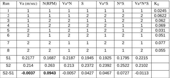
Table 5: effect of various parameters on KQ
Run Va (m/sec) N(RPM) Va*N S Va*S N*S Va*N*S KQ
1 1 1 1 1 1 1 1 0.0245
2 1 1 1 2 2 2 2 0.0622
3 1 2 2 1 1 2 2 0.062
4 1 2 2 2 2 1 1 0.069
5 2 1 2 1 2 1 2 0.031
6 2 1 2 2 1 2 1 0.051
7 2 2 1 1 2 2 1 0.077
8 2 2 1 2 1 1 2 0.055
S1 0.2177 0.1687 0.2187 0.1945 0.1925 0.1795 0.2215
S2 0.214 0.263 0.213 0.2372 0.2392 0.2522 0.2102
S2-S1 -0.0037 0.0943 -0.0057 0.0427 0.0467 0.0727 -0.0113
Table 6: effect of various parameters on η
Run Va (m/sec) N(RPM) Va*N S Va*S N*S Va*N*S η
1 1 1 1 1 1 1 1 0.673
2 1 1 1 2 2 2 2 0.68
3 1 2 2 1 1 2 2 0.678
4 1 2 2 2 2 1 1 0.698
5 2 1 2 1 2 1 2 0.72
6 2 1 2 2 1 2 1 0.75
7 2 2 1 1 2 2 1 0.73
8 2 2 1 2 1 1 2 0.791
S1 2.729 2.823 2.874 2.801 2.892 2.882 2.851
S2 2.991 2.897 2.846 2.919 2.828 2.838 2.869
S2-S1 0.262 0.074 -0.028 0.118 -0.064 -0.044 0.018
The advance velocity is playing a prominent role as far as efficiency is concerned.
4. Conclusions
1. The propeller which is a complex geometry can be analyzed numerically for performance evaluation.
2. The dynamic elastic scaling laws for shape adoptive composite materials along with hydro-elastic model prove to be an efficient tool for the analysis of marine propeller.
3. Taghchi’s orthogonal arrays can be used effectively for understanding the effect of various parameters and their interaction effects on the performance of a marine propeller.
4. This analysis can be used for designing a marine propeller for specific requirement by controlling the affect of various parameters.
5. References
[1] Taylor, D.w, “The Speed and Power and Ships”, Washington, 1933
[2] J.E.Conolly, “Strength Of composite Propellers”, reads in London at a meeting of the royal intuition of naval architects on dec
1,1960,pp 139-160
[3] Terje sonntvedt, “Propeller Blade Stresses, Application Of Finite Element Methods”, computers and structures, vol.4,pp 193-204,1950
[4] Chang-sup lee, yong-jik kim,gun-do kim and in-sik nho. “Case Study On The Structural Failure Of Marine Propeller Blades”
Aeronautical Journal, Jan 1972, pp87-98
[5] M.jourdian, visitor and J.L.Armand. “Strength Of Propeller Blades-A Numerical Approach”, the socity of naval architects and marine engineers, may 24-25,1978,pp 201-213.
[6] G.H.M.Beek, visitor, lips B.V.,Drunen. “Hub-Blade Interaction In Propeller Strength”, the socity of naval architects and marine
enginers, may 24-25,1978,pp191-194
[7] George W.Stickle and John L Crigler., “Propeller analysis from experimental data” report No.712, pp 147-164,1989
[8] W.J.Colclough and J.G.Russel. “The Development Of A Composite Propeller Blade With A CFRP Spar” Aeronautical Journal, Jan
1972, pp53-57
[9] J.G.Russel, “Use of reinforced plastics in a composite propeller blade”, plastics and polymers, Dec 1973, pp292-296
[10] Ching-Chieh Lin, Ya-jung Lee. “Stacking Sequence Optimization of Laminated Composite Structures Using Genetic Algorithm with
Local Improvement”, Composite structures, 63(2004), pp339-345
[11] Gau-Feng Lin “Three Dimensional Stress Analysis of a Fiber Reinforced Composite Thruster Blade”, the society of naval architects and marine engineers ,1991
[12] Jinsoo Cho and Seung-Chul Lee, “Propeller Blade Shape Optimization For Efficiency Improvement ”,Computer and Fluids, Vol.27,
pp 407-419,2002
[13] Charles Dai, Stephen Hanbric, lawerence mulvihill. “A Prototype Marine Propulusur Design Tool Using Artificial Intelligence And
Numerical Optimization Techniques ” ,Sname transations, Vol 102, 1994, pp 57-69.