©2013 JNAS Journal-2013-2-9/429-436 ISSN 2322-5149 ©2013 JNAS
Comparison of bulk driven, floating gate and sub
threshold methods in designing of a typical
amplifier
Abdullah Ahmadi
1, Sina Mohammadi
2, Mohammad Farahanchi
2and Abdolreza
Esmaeli
3*1. Department of Electrical Engineering,MahmoodAbaad University, MahmoodAbaad, Iran 2. Department of Electrical Engineering, University of Science and Technology , Mazandaran-Babol, Iran
3. Plasma Physics and nuclear fusion research school, Nuclear Science and Technology Research Institute, Tehran, Iran
Corresponding author: Abdolreza Esmaeli
ABSTRACT: Nowadays one of the most important parameters in designing analog circuits or even in the digital circuits is Reducing the consumption power of the circuit. In analog circuits, power consumption has a direct relationship with the values of circuit supply voltage and given the equation
in digital circuits the power can be directly related to the square of the supply
voltage value. It is therefore concluded that the reduction of power consumption of analog or digital circuits can be achieved by reducing the supply voltage. Another advantage of low supply voltage is that circuits are easy to transport because the small battery is used as the supply voltage on them. (e.g., audio devices).
Keywords: electronic amplifier, bulk driven, floating gate, sub threshold, power consumption, low voltage supply, CMOS, HSPICE.
INTRODUCTION
In the industry it is tried to reduce the electronic tools size for easier access to them such as audio devices including mobile. One of the ways to reduce the volume is using the low supply voltage. Because in doing so In addition to reducing the volume of the produced part, its power consumption will also be reduced. Although a reduced supply voltage is suitable to achieve this goal but there are limits to the threshold voltage of transistors and so that the supply value cannot be reduced. However, several methods have been proposed through which one can achieve to a voltage gain and appropriate margin with minimal supply voltage, among them there are sub-threshold, bulk-driven, floating gate that each has strengths and pitfalls. in the paper it is tried to compare 3 methods in order to deal with their strengths and pitfalls therefore a double floor circuit has been proposed which all mentioned methods have been used in order to design it to reach a 35 dB gain with 6 V supply .then in the next sections we have tried to compare the results considering briefly each method the intended circuit will be designed finally.
Floating gate MOSFET
Please Floating gate MOSFET has a structure similar to a conventional MOSFET. The only difference between the control gate and its substrate is that there is a poly silicon floating gate which is surrounded by an insulating silicon dioxide. (Blalock and Allen, 1995; Tai, 2006).
430
gate and body. The performance of the device is similar to a conventional MOSFET, which the only difference with the conventional MOSFET is that the voltage on the gate is not directly controlled by the input control but the inputs can control the voltage on the gate via capacitors & .. The transistors can also work in active and sub-threshold area based on voltage relationship between gate and source and threshold voltage value.
if transistor works in The active region. ( )
(1) (2) (3) (4) (5) (6)
However, if the transistor works in the active area , we will have the following equation: and source and threshold voltage value.
D
m
k
I
g
.(7)
Thus via a floating gate transistor the total threshold voltage of the device can be lowered by applying a DC voltage (Razavi, 2001; Bahmani and Fakhraie, 2000). We'll dim the threshold voltage by selecting values of the input capacitors even by selecting appropriately k2 and v1 we can reach the value Vth to zero. Its small signal model is shown in Figure 2.
The capacitor between gate and drain causes the output impedance of the transistor is reduced and the circuit gain dimed.
(A) (B)
Figure 1. floating-gate MOSFET model
Figure 2. Small signal model of MOSFET floating gate
(8)
2
1 2 2 0 2 1 2 1 0 2 1 V V c c V V C C V c c V c c c c V th th theq th theq
mFG m n Gi B FG D FG S FG T n i T Gi Gi B B FG S S FG D D FG FG FG t S FG D kg g C C C C C C V C V C V C V C Q v v v l w I
1 , , , 1 , , , 2 , / 2 THeq S FGV
V
,
0
0
g
g
C
C
g
mT GD
f
431
The transistor has various applications in the circuit .Due to insulator between floating gate the other nodes the load on it can be maintained for long periods of time. For this reason its important application is to make EPROM and EEPROM memories in digital circuits.
In analog circuits because the amount of threshold voltage of transistors can be controlled and reduced they are used in low voltage circuits. Input capacitance can cause an increase in circuit noise which is eliminated via suitable methods. The major disadvantage of transistors is the high cost during construction. (Rosenfeld and Kozak, 2004; Norman and Neff, 2008; Yang and Andrrou, 2009).
A Brief Study on the sub-threshold method
When the gate - source voltage of a MOSFET transistor is less than the threshold voltage , the Channel is in weak inversion which the area of the performance is called sub-threshold transistor.
Device consumption current in the region is an exponential equation:
(9)
(10)
(11)
In this region because the amount of transistors current is very low, circuit consumption power will below and also voltage drop on the drain - source terminal is low. Because of these two above important properties in designing the low voltage and power circuits this structure is used. Nearly Similar to a transistor BJT, MOSFET transistor trans-induction is directly related to the transistor current in the sub-threshold area (Rosenfeld and Kozak, 2004) Because in the sub-threshold area there is low transistor current so the trans-induction value is low too. But given the gain value is equal to , it is clear that the channel length plays an important role in the operation thus due to channel length increase the gain value will rise. But its weakness is that due to very low transistor current the trans-induction value of transistor is very small , as a result the gain width and extent of circuit is reduced Because - for example - in a two-floor circuit , the value of circuit single gain width is directly related to the value of input floor trans-induction given the equation (14). Therefore, this type of circuit is used in the low frequency.
c m
c g
GBW
(12)
In this method we make use of the auxiliary and folded cascade circuit with it to strengthen further gain. This structure has pitfalls including:
1 It has no a good frequency response. 2 For The values VDS 3kT/q,the equations
m
g &r0are non-linear and makes it difficult to design.
3 To increase the gain of a transistor the devices width should be high and so the speed of the circuit will be reduced.
Investigation of body-driven circuits
Dependency of the threshold voltage to the body voltage
Usually the body terminal voltage in some cases is named as source of error. But the reality is that although the body terminal and the voltage on which and even the voltage deference between this terminal and especially the source terminal create some problems in designing and probably calculation and we should care about it as a second gate for this and even apply input signal to it and expect the signal amplification by the device in these conditions. Given that different discussions set forth for the arrangements with gate input (gate-driven) such as voltage amplification value , frequency response quality , input & output voltage limit, etc. It is necessary to adopt that whether the body can be as input, the above discussion should investigated. The chapter aims to learn more about transistor circuits with signal input to the body terminal (Bulk - Driven), and exploring some important features of amplifier.
I r
q T nK
D I m g
T nk
tn v GS v q
e q
T nK
l w K DS I
1 0
/
) (
exp "
2
432
with respect to the threshold voltage relations in the devices PMOS, NMOS:
√ -√ ) NMOS
(13)
) 2 2
(
0 f VSB f
th V TH
V
PMOS (14)
(15)
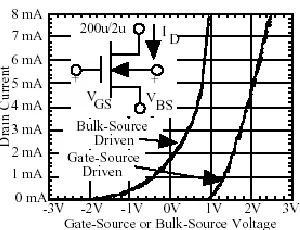
It can be seen that the rate of voltage changes of body-source may impact on the threshold voltage. For example, as shown in Figure 3 due to increase of the body terminal voltage in relation to the source, threshold voltage is reduced. Thus, given the drain current relationship with threshold voltage reduction the drain current increases. Another point is presumable from equations (15),(16) and (17) is that the rate of changes of transistors current is less than that of body-source voltage in comparison to that of source-gate voltage , So when the devices are being used up by the body-driven method they have more input changes than gate –driven state . The quality of the above mentioned matter is shown in Figure 3.
According to Figure 3 in a transistor, n-type increases due to increase in the body voltage relative to the transistor current source.
But what is important is that the body terminal voltage value should also be limited because pad lock or leakage current through device internal diodes will effect on the transistor function.
If the input voltage of the body (in the device NMOS) increases, internal bonds PN between the body and source and that of the drain and body source will become active and even activates the links (Figure 4). In addition unwanted BJT transistors may be activated and pad locking happen.
Figure 3. the drain current with respect to body-source and gate - source voltage
Figure 4. internal structure of an NMOS
SB VSB
V
Th iD GS
m
s TH Th
iD s
mbs
V
f
V
V
ID
g
B
V
V
V
B
V
ID
g
TH
2
2
)
(
)
)(
(
2
) (
2 GS th
ox n
D V V
l w C
433
In DC analysis of transistor circuit , the drain current can be calculated via following equation regardless of any arrangement.
20
0 2 2
2l V V f V f
w C
ID
ox GS TH
SB
(16) Which the following equations are defined in:
Saturation region TH GS
DS V V
V
(17)
Triode region TH GS
DS V V
V
(18) Cut-off region TH GS V V (19)
So the DC voltage of body - source terminal has a feature either in circuits(Bulk-Driven) or in circuits (Gate-Driven) and will change the operating point to the same extent .In Small-signal analysis of a device as body-driven or with gate input or observing small signal model of the amplifiers we will have the following equations .
Latch up:
(20)
(21)
(22)
0.2x0.4 (23)
VBS 2 f 0.25 0.5V
2
(24)
In The small-signal analysis, the drain current in addition to dependency on the gate - source small signal voltage ( gs
V
) is depended as well to the Body - source small-signal voltage that the dependency value gmand gmbs is
defined via trans-inductions & which in the equations described if VBS 2 f 0.25 0.5V
2
, gmbs is more than gm
, but the pitfall of this is the high leakage current and probably the pad locking Relations (Philllip, 2003). As it has been shown in the above equations gmbsgm , this means that the trans-induction value gm could even be five
times larger than that of trans-induction gmbs .i.e. The value of the signal strength by inserting the input into the
body is 5 times lower than signal insertion into the gate, and then it is also the weakness of body-driven circuit . Another weakness with the body input is its speed reduction relative to the moment the same device works with input gate frame (Pease Robert, 2000).
driven gate t driven bulk t
f
f
8
.
3
(25)
Comparison of methods
Figures 5 ,6 and 7 are respectively the circuits with quite similar structure which their differences are: how to insert the input voltage to the circuit, how to bias and also kind of input transistor. The circuit K in the first floor is a PMOS differential double floor circuit that was used.
The second floor circuit is a low voltage amplification AB. a voltage source was used to bias the second floor circuit. We examine 3 parameters such as size ,phase margin and consumption power to compare the methods for
434
achieving the voltage gain in 35 dB. Figure 5-1 shows the circuit with differential pair input in the body-driven layout.
Figure 5. The circuit with body-driven input
Table 1. Size of circuit transistors and elements in figure 5
M
L(µ) W(µ)
M1 1 1.7
M2 1 1.7
M3 1 4.8
M4 1 8
M5 1 2
M5 1 2
M7 1 7
Figure 6. Frequency response of the circuit in Figure 5
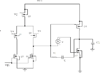
Figure 7. the proposed circuit which all devices are biased in sub-threshold region
Table 2. The transistors and elements size of the circuit in Figure 7
elements Size
CL 5p
R 0.1k
C 10n
AV 35db
PH 75
P(w) 946n
elements Size
elements Size
CL 5p
C 1.3p
R 200K
AV 35db
PH 30
P(w) 611n
M L(µ) W(µ)
M1 10 170
M2 10 170
M3 2 70
M4 2 60
M5 2 40
M6 2 40
435
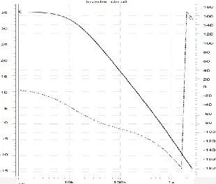
Figure 8. Frequency response of the circuit in Figure 7
Figure 9. Circuit with floating gate input
We will discuss the circuit via floating gate transistor inputs.
Table 3. Size of the transistors and elements of circuit in Figure 9
M L(µ) W(µ)
M1 2 15
M2 2 15
M3 2 12.5
M4 2 2
M5 2 5
M5 2 5
M7 2 5
Figure 10. Frequency response of the circuit in Figure 9
It can be seen that in Comparison of phase margin and circuit size (occupied space) the body –driven is more preferred and the sub-threshold method will occupy more volume.
In comparison of power consumption three methods are perceived. The sub-threshold method has less consumption power in proportion to two other methods and the floating-gate method will have more consumption power.
elements Size
CL 5p
C 1f
R 0.5K
AV 35db
PH 82
436
CONCULSION
In the paper after designing a double floor circuit by 3 methods which has been carried out through 6 V supply voltage; it was evident that even if all of them can be used in low supply voltage very well but depending on the overall goal everyone can be used. For example, if circuit design target is led to very low consumption power the sub-threshold technique is the most appropriate one However; its low frequency response still remains as before or if the objective of circuit design is with a suitable volume of bulk.
REFERENCES
Bahmani and Fakhraie SM. 2000. ”A Rail To Rail Constant Gm 1-Volt cmosOpamp”proceeding of the IEEE international symposium on circuit and system,VOL.2, PP.669-672.
Blalock B J and Allen PE. 1995. ”A low-voltage,Bulk-Driven MOSFET current Mirror for CMOS Technology”IEEEInternational Symposiom on Circuit and System,ISCAS95.,VOL.3, PP.1972-1975.
BS. 2003. King Fahd university of petroleum and Minerals "Ultera-LowVoltage Operational plifier".
Norman L, Neff J. 2008. "A Novel Floating Gate Circuit Family with Subthreshold Voltage Swing Ultra Low Power operation" International conference.on circuit and System Dec, pp.12-16.
Pease R. 2000. "The Design Of Band- gap circuits"IEEE 1990 Bipolar and circuitTechnology Meeting ,PP 214-218.
Philllip E. 2003. Allen Benjamin J.Blalock scool of electrical and computer engineering Georgia institute of technology Atlanta"Low voltage analog circuits using standards Cmos technology".
Ramirez J. 1996. "Low Supply Voltage Ota Artitecture Using Floating Gate Transistors"IEEE Electrical and computer engineering.
Razavi B. 2001. Design of Analog CMOS Integrated circuits New York:Mc Graw-Hill.
Rosenfeld J and Kozak M. 2004. “A Bulk-Driven CMOS OTA with 68db DC Gain,” 11 th IEEE International conference.on circuit and System,ICECS 2004,dec,pp.5-8.
Tai C F. 2006. ”Using Bulk-Driven Technology Operate In subthreshold to Region to Design aLow Voltageand Operatoinal Amplifier”IEEE Circuit and System. pp1032-1035.