©2015 JNAS Journal-2015-4-2/108-115 ISSN 2322-5149 ©2015 JNAS
Tensile properties of strip and figure-eight
shappedd samples of Chopped Strand fiberglass
Aboulfazl Safari
1, Morteza Mansoori
2, Mandana Abedini
3*and Fauziah Ahamd
41- Buein Zahra Technical University, Talegani Square, Buein Zahara, Gazvin, Iran 2- Zanjan Azad University, Moalen Street, Zanjan, Iran
3- Buein Zahara Azad University, Buein Zahara, Gazvin, Iran
4- School of Civil Engineering, Engineering Campus, University Sains Malaysia, 14300 Nibong Tebal, Pulau Penang, Malaysia
Corresponding author:
Mandana Abedini
ABSTRACT: Scrap tyres have been used in many applications such as geotechnical engineering. It has been found that scrap tyres are a favourable material in this field. However, its high deformability is a matter of concern. Some solutions have been investigated while for having a very limited deformation, an alternative to scrap tyre must be provided. High tensile stress and low tensile strain of fibreglass would make it a good alternative to scrap tyres. This paper evaluates fibreglass as an alternative material to scrap tyre in some cases. Tensile tests have been carried out on strip and ‘8’ shappedd samples of fibreglass and scrap tyre. Fibreglass samples were produced from a Chopped Strand mat—a very low cost- material that cured by a resin and a hardener. Statistical analysis on the results of strip samples indicated that in the maximum tensile test, fiberglass samples experience 2% while tyre samples experience 11% of strain respectively. As for ‘8’ shappedd samples, It was found that values of the elongation and strain of tyre samples at maximum tensile load are greater than of what obtained for fiberglass up to 70% and 105.6% respectively.
Keywords: Fiberglass Chopped Strand, Tensile Load, Tensile strain, Scrap tyre.
INTRODUCTION
Application of recycled tyre in geotechnical engineering purposes would be a desirable method covering all environmental concern as well as economical and technical aspects. The excellent mechanical and physical properties such as light weight, high tensile strength, and durability have been addressed in many studies (1-4). A review of literature indicated that recycled tyre is mainly grouped in three categories, shredded, whole and bale (1). Many studies presented good results where utilizing shredded tyre as construction material. Bosscher ). (5) carried out a study to develop design procedures for utilizing shredded recycled tyre as a light-weight fill material in highway construction. Humphrey (6) presented some projects in which tyre shreds were used as light-weight fill for highway embankment construction, bridge abutment backfill, thermal insulation, and drainage layers. Humphrey and Tweedie (7) performed a full-scale project using tyre shreds to reduce horizontal pressure in retaining walls. Some other researchers focused on improving clayey soil with chip tyre presenting the engineering properties of the clay-tyre composite (8-11) . Many others performed studies on sand-tyre mixtures (12-15).
109
The use of tyre bale is more suitable from the economical point of view as well as for using significant volume of recycled tyre. A few studies have been presented application of scrap bale tyre in transportation projects and road foundation on soft ground (1, 19).Despite many advantages which have been reported for scrap tyres as a reinforcement material, a review of literature indicated that the main concern of using scrap tyres as soil reinforcement and slope stability element would be its high deformation characteristic. In some geotechnical engineering project such as retaining walls where limited amount of strain is required, this high deformation would be a point of concern. O'Shaughnessy and Garga (20) indicated that large displacements were required to fully mobilize the ultimate pull-out capacity of whole tyre. The results showed that tyre samples experienced a large strain ranged from 19.6% to 44.6%. Gerscovich ).(21) also reported that 610 mm of displacement were required to achieve maximum pull-out resistance where whole cut tyre reinforcement were subjected in pull-out test.
To control the high deformability some solutions have been investigared. Using different tyre configurations of tyre reinforcement elemen such as 1*2, 1*4, 2*2, 2*4, diamond and triangle lead to different frontal strain under pull-out test (22). Adtionally, using different shappeds of tyre reinforcement element have been reported to be effective parameter to reduce deormability(18, 23). However, having a very limited deformability needs to provide the other options by using a new materials.
Fibreglass, in addition to very low strain, presents unique properties such as affordability, cost effectiveness, light weight, durability, high tensile strength and high corrosion resistance which seem to be a suitable and desirable alternative to scrap whole tyres where deformation must be limited. Fibreglass has been the most common choice for reinforcement in many researches over the past 40 years (24-27), however, only a few studies have addressed the applications of fibreglass to the field of geotechnical engineering (28-30). A comparative study on the tensile strength of fibreglass and scrap tyre presented by Safari and Fauziah (31) indicated a strain of 2% for strip sample of fibreglass while a similar sample of scrap tyre experienced 11% at maximum tensile load.
Since reinforcement elements must provide additional stability for the soil mass, its tensile strength is a key parameter that needs to be measured. In this paper, the first series of tensile tests were performed on fiberglass strips to present its tensile properties. In the second series of tensile tests, the ‘8’ shapped samples of fiberglass were used to show its workability as reinforcement element. Strip and ‘8’ shapped sample of recycled tyre were subjected to tensile tests for comparison purpose too.
Experimental program Tensile test machine
Two types of tensile test machines were used in this experimental program to measure tensile properties of strip and ‘8’ shapped samples. The Instron 3690 series actuator with a 250 kN loading capacity was used for performing tensile tests on the strip samples of fibreglass and tyre. This machine is a double acting, equal area hydraulic piston that can exert both tensile and compressive forces. The machine is able to apply load on the samples with speeds of 0.5–500 mm/min.
Another serious of tensile tests were carried out on ‘8’ shapped samples of the fibreglass and whole tyre using a universal tensile machine manufactured by Shimadzu with a maximum capacity of 1000 kN and a minimum readability of 1 kN (0.1 T). This machine is able to apply load on samples with speeds of 0.5–500 mm/min. The original clamps of the machine were not suitable for the tensile tests on the ‘8’ mat; thus, two new jaws were designed for this test (Fig 1).
110
Sample preparation Fibreglass
In this experimental investigation, tensile tests were performed on 1, 2, 3, and 4 layers of strip samples of fiberglass, with 1 mm, 2 mm, 3 mm, and 4 mm thickness respectively. ‘8’ shappedd samples made by 3 layers of fibreglass, with a thickness of 3 mm, were used. The samples were produced from Chopped Strand fibre mats (Fig 2) cured by resin and hardener. This type of fibreglass was chosen because of its very low-cost and properties, which me)l technical requirements (e.g. tensile stress and strain).
Figure 2. Chopped Strand Fiberglass used in this study
To develop fibreglass samples, the first step is to construct a suitable mould. The mould can be made from a variety of materials. These materials include wood, plaster, polyester resin, and fibreglass. In this study, we have used plywood and zinc plate, as shown in Figure 3.
It should be noted that the finishing surface of the mould must be very smooth. This will provide a smooth surface for the final products. Moreover, this will help to release the mould easily. The next stage is to apply mould release wax, i.e. 3IlGMIRROR GLAZE WAX used in this study. This wax is in paste form and has high carnauba content. Three thin coats of wax were applied using a clean, lint-free cloth by hand. It should be applied using an overlapping circular motion to make sure the wax covers all areas. Each layer of wax needs 30–40 minutes to be dried
Figure 3.Applying wax on ‘8’ shapped mould
111
Figure 4. ‘8’ shapped fibreglass developted for tensile test
With reference to the ASTM D4595 standard, in a similar approach, some strip samples of fibreglass were developed with a width of 100 mm and a length of 300 mm and were subjected to a tensile test.
Tyre
Six strip samples of the recycled tyre were examined. They cut to have a width of 100 mm and a length of 300 mm and fed to the tensile test machine. For ‘8’ shappedd samples, some recycled tyre of size 175/70R13 were obtained from Malaysian Goodyear brand. A cutter machine was used to cut their side walls, and then, their middle points were tightened together with screws to make an ‘8’ mat of tyres.
Testing Program.
RESULTS AND DISCUSSION
Tensile test on strip samples of fiberglass and tyre
The tensile tests were performed on strip samples as described in Section 3.3. Five parameters namely, maximum tensile load (MTL), Elb (elongation at break), maximum tensile stress (MTS) tensile strain at maximum tensile load (TStMTS), and Young’s modulus (E) are given in Table 1.
Table 1. The results of tensile test on the strip samples of fiberglass
Sample Thickness MTL Elb MTS TSt MTS E
No mm kN mm MPa % MPa
1 1 6.17 1.67 61.72 1 5249.67
2 1 3.3 2.6 33 1 5410.85
3 1 5.95 1.53 59.49 1 5834.75
4 1 5.66 1.45 56.57 1 5223.33
5 1 7.46 2.46 74.64 2 4783.91
6 1 5.7 1.47 57 1 5300.31
Mean 1 5.7 1.86 57.07 1 5300.5
Standard deviation -- 1.35 0.52 13.53 0.4 338.52
7 2 15.07 2.3 75.33 2 5069.27
8 2 18.46 2 92.3 2 6296.84
9 2 15.53 2.49 77.66 2 4759.39
10 2 17.14 2.63 85.68 2 5204.81
11 2 11.96 2.06 59.81 1 4687.17
12 2 16.3 2.52 81.5 2 5203.17
Mean 2 15.74 2.33 78.71 2 5203.4
Standard deviation 2.21 0.26 11.05 0.4 579.18
13 3 24.97 2.34 83.25 2 4768.65
14 3 23.31 1.52 77.7 2 -
15 3 20.86 2.28 69.52 2 4218.8
16 3 27.65 2.73 92.18 2 4438.63
17 3 19.53 2.44 65.09 2 3701.6
18 3 22.23 2.48 74.1 2 4324.12
Mean 3 23.1 2.30 77.0 2 4290.36
Standard deviation 0 2.92 0.41 2.75 0 388.47
19 4 18.68 1.56 46.71 1 3969.79
20 4 21.7 1.61 54.26 1 4139.66
21 4 18.57 3.7 46.43 1 4505.15
22 4 24.08 1.81 60.21 1 5241.41
23 4 25.88 2.01 64.7 1 5124.82
24 4 23.1 1.95 57.75 1 4673.50
Mean 4 22.00 2.11 55.01 1 4609.06
112
According to Table 1, firstly, the MTL increases as thickness increases, for all thicknesses except 4 mm. Secondly, MTL increases with thickness but in a decreasing rate. Increasing the thickness from 1 mm to 2 mm and from 2 mm to 3 mm led to increase MTL 276% and 146.7% respectively. Finally, the maximum MTL value, 27.65 kN, was obtained with a thickness of 3 mm. It should be noted that in the following of this study thickness of 3 mm of fiberglass, as optimum thickness, has been subjected to further study.The mean MTL for 3 mm samples is 23.1 kN, with corresponding standard deviation of 2.92 kN. Statistical probability analysis showed that the probability of MTL greater than 15.34 kN is 99.7% .A similar approach performed on stain values showed that the probability of TSt≥2% is 100%.
The stress-strain curves of samples numbers 13–18 (3 mm thickness) from Table 1, shown in Fig 5, indicated that the relationship between stress and strain is approximately linear and Hook’s law is valid for this material. Thus, to find the best relationship between (stress) and (strain), linear regression analysis was performed, and the results are summarized in Table 2.
Figure 5. Stress- strain cure for fiberglass strip with thickness of 3 mm
Table 2. Stress- strain relationship of fiberglass strips with thickness of 3 mm
Sample No Equation R2(%)
13 =4728 98.9 14 =39648 99.1 15 =4106 98.9 16 =4453 96.7 17 =3642 98.2 18 =3581 97.4
The best fitting lines were obtained by zero value of intercept. The values of the coefficient of determination (R2), greater than 96 indicated good linear relationship between σ and Є.
In the next series of tensile test as shown in Table 3, strip samples of tyre were fed to tensile machine. The mean value of MTL and its standard deviation are 21.07 kN, and 1.87 kN respectively. The statistical analysis indicated that the probability of MTL greater than 15.95 kN is 99.7 %. The similar method indicated that the probability of TStMTS greater than 6.96 is 99.7 %.
Table 3. The results of tensile test on the strip samples of tyre
sample No Thickness MTL Elb MTS TSt MTS E
(cm) kN mm MPa % MPa
1 10.88 19.49 38.04 17.91 9 174.65
2 11.20 21.33 36.53 19.04 10 170.53
3 10.47 20.66 45.1 19.73 11 168.34
4 10.34 20.47 43.5 19.8 12 158.17
5 11.23 24.67 37.75 21.96 13 155.39
6 11.24 19.82 45.89 17.63 10 168.72
Average 10.89 21.07 41.13 19.04 10.8 165.96
Standard deviation 0.40 1.87 4.15 2.01 1.4 7.5
113
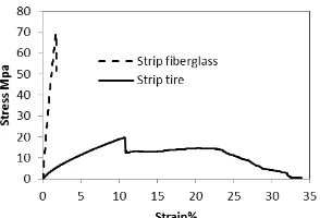
obtained for tyres. Meanwhile, the tyre sample experienced a very high strain at the maximum tensile load, 11%, which is greater than of that recorded for fiberglass up to 450%.Figure 6. The stress-strain curve for fiberglass sample No.15 and tyre sample No. 3
Tensile test on ‘8’ shapped sample of fiberglass and tyre
A series of tensile tests were performed on the fibreglass ‘8’ shapped and parameters namely, MTL (maximum tensile load), ElMTL (elongation at maximum tensile load), StMTL, the MEl (maximum elongation), and MSt (maximum strain), were measured as shown in Table 4. Using the data in Table 4, the mean MTL and corresponding standard deviation were calculated to be 6.907 kN and 0.55 kN, respectively. Statistical probability analysis carried out on the results showed that the probability of MTL being greater than 5.64 kN was 98.93%.
Table 4. The results of tensile test carried out on ‘8’ shape samples of fiberglass
Sample No. MTL EMTL StMTL MEl MSt
kN mm % mm %
Fg1 6.53 57.784 6.719 58.246 6.77
Fg2 7.61 66.678 7.753 67.068 7.80
Fg3 6.69 60.72 7.061 61.18 7.11
Fg4 6.00 63.232 7.353 63.948 7.44
Fg5 6.27 60.20 7.000 62.80 7.30
Fg6 6.69 60.20 7.000 60.88 7.08
Fg7 7.08 59.69 6.941 60.37 7.02
Fg8 7.26 65.51 7.617 66.25 7.70
Fg9 7.44 58.13 6.759 58.70 6.83
Fg10 7.50 64.71 7.525 65.35 7.60
Mean 6.907 61.69 7.17 62.48 7.26
Standard deviation 0.55 3.13 0.36 3.10 0.36
According to the results, strip samples are able to withstand tensile load higher than ‘8’ shapped. This can be illustrated by free diagram and the breaking mechanism of the strip and ‘8’ shapped samples. Fig 7 shows the free diagram of a strip sample. Since the tensile load was applied axially, there is no shear and moment in the breaking section. It means that the sample breaks under a net tensile load.
Figure 7. Internal forces in breaking section of strip fiberglass sample
Free diagram of a ‘8’ shapped sample is shown in Figure 8. It should be noted that the breaking section of all samples was section B, as shown in Figure. 8. As shown in the diagram, tensile force, shear force, and moment are not equal to zero in the breaking section. Existence of shear force and moment in the breaking section caused the
T T
T
T M=0 V=0
A A A
114
mechanism of shear breaking. On the other hand, the results of tensile tests on ‘8’ shapped, shown in Table 4, indicated the shear resistance of the fibreglass sample rather than its net tensile strength.This would not be a drawback for installing fibreglass ‘8’ shapped in soil layers as reinforcement element. It can be illustrated by a different failure mechanism in reinforced soil. Since the samples will be covered by compacted soil materials in a real project, the different failure mechanism would be experienced. (16) showed that the ultimate pull-out capacity of tyre mats in low embankments is primarily governed by the shear strength of the soil. However, further studies on the pull-out behaviour of fibreglass ‘8’ shapped will be helpful to investigate this part.
Similar approaches were adopted to determine the mean and standard deviation values of ElMTL and SMTL showed in Table 4. The results indicated that the probability of ElMTL being greater than 54.49 mm and StMTL being greater than 6.34% was 98.93%.
The last series of the tensile tests were performed on the tyre ‘8’ shapped samples. Recorded parameters are summarized in Table 5.Similar approach indicated that probabilities of MTL being greater than 17.6 kN, ElMTL being greater than 92.72 mm, and StMTL being greater than 13.04 were 98.93%.
Table 5. The results of tensile test carried out on ‘8’ shape samples of tyre
Sample No. MTL ElMTL StMTL MEl MSt
kN mm % mm %
Ti1 26.06 108.54 15.29 108.9 15.3
Ti2 26.69 148.09 20.86 156.5 22.0
Ti3 28.46 122.65 17.27 123.1 17.3
Ti4 36.22 128.12 18.05 133.2 18.8
Ti5 39.35 126.92 17.88 139.1 19.6
Ti6 42.7 145.13 20.44 145.9 20.5
Ti7 43.72 133.60 18.82 145.9 20.5
Ti8 45.78 168.96 23.80 174.5 24.6
Mean 36.12 135.27 19.05 140.89 19.83
Standard deviation 8.05 18.5 2.6 20.09 2.84
The important finding of the results is the values of ElMTL and StMTL of fibreglass and tyre ‘8’ shapped samples. It was found that values of ElMTL and StMTL of tyre sample are greater than of what obtained for fiberglass up to 70% and 105.6% respectively.
The other point which need to be clarified is that why strip sample of tyre presented tensile load lower that ‘8’ shapped? It is reasonable to infer that the cutting process of the tire samples induced major disturbances in the designed ring structure of the tire. The ring structure of a tire is a continuous element that is designed to distribute stress evenly to the entire structure (17).
CONCLUSION
This study presents the tensile properties of chop strand fibreglass as an alternative to scrap tyre where limited deformation is necessary. According to the results, fiberglass is a capable material to control deformation. In fact, fiberglass strip sample presents strain lower that recycled tyre up to 450%. Meanwhile, utilizing ‘8’ samples of fiberglass in tensile test resulted in decreasing ElMTL and StMTL up to 70% and 105.6% respectively. This is a very important finding which shows suitability of this material to control deformation. However, further study on pull-out behaviour of fiberglass as well as a field trial project constructed by fiberglass would be helpful to show it workability as soil reinforcement element.
REFERENCES
Akbulut S, Arasan S and Kalkan E. 2007. Modification of clayey soils using scrap tire rubber and synthetic fibers. Applied Clay Science, 2007. 38(1-2): p. 23-32.
Bilida GV. 1971. Strength and deformation of fiberglass under shear. Problemy Prochnosti, 1971. 3(7): p. 787-792.
Bosscher PJ, Edil TB and Kuraoka S. 1997. Design of Highway Embankments Using Tire Chips. Journal of Geotechnical and Geoenvironmental Engineering, 1997. 123(4): p. 295-304.
Cetin H, Fener M and Gunaydin O. 2006. Geotechnical properties of tire-cohesive clayey soil mixtures as a fill material.
Engineering Geology, 2006. 88(1-2): p. 110-120.
115
Garga VK and O’Shaughnessy V. 2000. Tire-reinforced earthfill. Part 1: Construction of a test fill, performance, and retaining wall design. Canadian Geotechnical Journal, 2000. 37: p. 75-96.
Gerscovich DMS. 2004. Scrap Tire: A Civil Engineering Material. International Journal of Engineering, 2004. 17: p. 1-24. Golestanian H. 2007. Expeimental determination of fiber mat permeameability of chopeed fiberglass mats. Composite Materials,
2007. B, 2T6: p. 105-106.
Hataf N and Rahimi MM. 2006. Experimental investigation of bearing capacity of sand reinforced with randomly distributed tire shreds. Construction and Building Materials, 2006. 20(10): p. 910-916.
Ho MH and Chan CM. 2010. The Potential of Using Rubberchips as a Soft Clay Stabilizer Enhancing Agent. Ho, Meei Hoan, 2010. 4, No.10: p. 122-131.
Huat BBK, Aziz AA and Chuan LW. 2008. Application of Scrap Tires as EarthReinforcement for Repair of Tropical Residual Soil Slope. Electronic Jounal of Geotechnical Engineering 2008. 13, Bund. B: p. 1-9.
Humphrey DN. 1999. Civil engineering application of tire shreds, in The Tire Industry Conference. 1999: South Carolina. p. 16. Humphrey DN and Tweedie JJ. 2002. TIRE SHREDS AS LIGHTWEIGHT FILL FOR RETAINING WALLS.
Issa M. 1994. Static response of fiberglass pretensioned columns Journal of Struetural Engineering, 1994. 120: p. 14.
Marefat V and Soltani-Jiagheh H. 2011. Laboratory Behavior of Caly-Tire Mixture. Worl Applied Sciences Journal, 2011. 13(5): p. 1035-1041.
Orlov DL and Gorin AE. 1999. Application of fiberglass frit in construction engineering. Glass and Ceramics, 1999. 56: p. 199-203.
Oreste PP. 2009. Face stabilisation of shallow tunnels using fibreglass dowels, in Proceedings of the Institution of Civil Engineers, Geotechnical Engineering 162. 2009: Politecnico di Torino, Italy. p. 14.
O'Shaughnessy V and Garga VK. 2000. Tire-reinfored earthfill. Part 2: Pull-out behaviour and reinfored slop design. Canadian Geotechnical Journal, 2000. 37: p. 19.
O'Shaughnessy V and Garga VK. 2000. Tire-reinforced earthfill. Part 2: Pull-out behaviour and reinforced slope design.
Canadian geotechnical journal, 2000. 37(1): p. 97-116.
O’Shaughnessy V and Garga VK. 2000. Tire-reinforced earthfill. Part 3: Environmental assessment. Canadian Geotechnical Journal, 2000. 37: p. 117-113.
Pierce CE and Blackwell MC. 2003. Potential of scrap tire rubber as lightweight aggregate in flowable fill. Waste Management, 2003. 23(3): p. 197-208.
Pokharel SK. 2009. Experimental Evaluation of Influence Factors for Single Geocell-Reinforced Sand. 2009, US Transportation Research Board (TRB) Annual Meeting: Washington, D.C.
RESULTS OF FULL SCALE FIELD TRIALS. 2002. in Proceedings of the Workshop on Lightweight Geomaterials. 2002. Tokyo, Japan.
Safari A and Fauziah A. 2011. A comparison study on the tensile strength of fiberglass and scrap tire strips World Applied Sceince 2011.
Sakr M, El Naggar MH and Nehdi M. 2005. Lateral behaviour of composite tapered piles in dense sand. . Geotechnical Engineering, 2005. 158: p. 145-157.
.
Tanchaisawat T. 2010. Interaction between geogrid reinforcement and tire chip-sand lightweight backfill. Geotextiles and Geomembranes, 2010. 28(1): p. 119-127.
Thomas MHL and Yu. HJ 2006. Laboratory Study on the Mechanical Behavior of Tire Chip‐Sand Mixture. Pavement Mechanics and Performance 2006. GSP 154: p. 157-164.
Winter MG, Johnson PE and Reid JM. 2005. Construction of Road Foundation and Soft Ground Using Light Weight Tyre Bales
in Proceeding of international conference on problematic soil. 2005. Eastern Mediterranean University, Famagusta, N. Cyprus, 775-782.
Yoon YW, Heo SB and Kim KS. 2008. Geotechnical performance of waste tires for soil reinforcement from chamber tests.
Geotextiles and Geomembranes, 2008. 26(1): p. 100-107.