© 2018 IJSRSET | Volume 4 | Issue 2 | Print ISSN: 2395-1990 | Online ISSN : 2394-4099 National Conference on Advanced Research Trends in Information and Computing Technologies (NCARTICT-2018), Department of IT, L. D. College of Engineering,
Ahmedabad, Gujarat, India In association with International Journal of Scientific Research in Science, Engineering and Technology
The Study of Effectiveness of Material and Geometry of Different
Outrigger Structural System: A Review
Iqra A. Khan*1, N. G. Gore2
*1ME student, 2Assistant professor
Civil Engineering Department, MGM’s College of Engineering and Technology, Nevi Mumbai, Maharashtra,
India
ABSTRACT
The construction of the highrise structure is the need of the hour. Since the increase in population has led the world to the land space crises. Higher the structure, higher will be the challenges against its stability. Lateral forces are the most important factors to be considered when it comes to controlling lateral deflection of the building. And for that several lateral load resisting systems have been implemented in the field since years. Outrigger-belt truss system has been found to be one of the most effective system and hence are used worldwide. This system can be used as per the need and type of building such as only outrigger, outrigger-belt truss, only belt truss, outrigger wall and belt wall, only belt wall etc. Steel outriggers have been studied more by the researchers. This paper presents a review of effectiveness and selection of material and depth of outrigger. From the review, it is concluded that selection of material differs with the type of building, also, increase the depth of the outrigger, stiffer the structure will be.
Keywords: Outrigger, Belt Truss, Belt Wall, Depth, ETABS, Storey, Concrete
I.
INTRODUCTIONThe development in concrete technology over the twentieth century covering material, structural system, analysis and construction techniques, made it possible to build concrete tall buildings. As the height of a building is increased, the material starts to play more important roles for the stability of the structure. Steel is one of the most important materials used in
construction and it is used in different ways to improve its performance [1].
introducing the outrigger structural system. Apart from that, some disadvantages are also associated with this system, but by using outrigger system optimally, that can be minimized too [2].
Different methods can be used to strengthen the structure such as belt wall system, soil reinforcement method, seismic performance evaluation method etc. [3].
Fig. 1 Typical Outrigger-Belt truss system
The high strength concrete in combination with steel sections provide an effective structural system. Design codes along with advanced analysis techniques and constructability issues were also discussed [4].
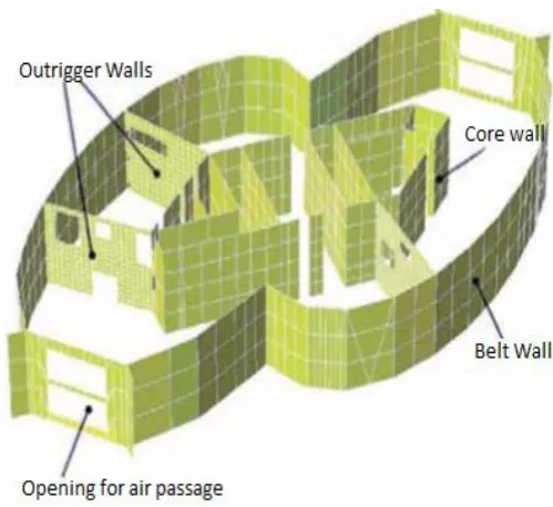
Fig. 2 Typical Outrigger wall-Belt-wall system
Source: Ranjith Chandunni et al. [6]
II.
LITERATURE REVIEWhad become higher and complicated, they went for seismic evaluation method.
John Merrick [4] presented the main challenges associated with one of the tallest structures i.e. Dubai Tower, a 438m in height in Doha Qatar and the innovative design solutions to overcome the problems were also discussed. It was studied that the high strength concrete in combination with steel sections provided an effective structural system. Design codes along with advanced analysis techniques and constructability issues were also discussed. The perimeter columns were made up of combination of high strength reinforced concrete and concrete-filled steel tubes. The composite outriggers and belt truss are constructed at three plant room levels i.e. between floors 21-23, 52-54 and 86-88 that engaged the perimeter columns. In an outrigger and perimeter belt truss system, the additional loads are shared with the adjacent columns hence increasing the overall efficiency of the lateral resisting system.
Jong Soo Kim [5] gave out the detailed design difficulties and optimum solutions to the same for the W-Project, a 70-storey mixed-used building in Busan, Korea. The foundation of the building was one of the most challenging tasks because of the soft soil and hence mat-foundation was adopted. Since the structure is very tall, lateral forces are very important to be taken into account. To deal with lateral forces, 3 proposals were made, first, providing RC outrigger and RC belt walls, second- providing steel outrigger and steel belt truss. The former had a great disadvantage of time delay whereas the latter had the lack of stiffness. To deal with these problems, the third system was introduced in
which RC fin walls were provided on all floors with RC outrigger wall-steel belt truss which made the structure 40% stiffer. The system had been provided on 30th and
57th floor of the building. Delay joints are also provided
on outrigger wall to reduce the vertical shear force. The project has been given a security with the help of Health Monitoring System to take care of any damage if occurred.
Ranjith Chandunni et al. [6] discussed the important
design aspects of the Dubai Multi Commodity Centre’s Almas Tower which is a 360m high slender office. Also, they described the design of the tower’s spire, which
featured tuned mass dampers. The principal structural framing of the tower consists essentially of a tube-in-tube system. This is made up of a reinforced concrete peripheral frame and a central core wall, which are connected to each other by central spine beams on each
floor and outrigger walls at service floor levels. They
studied the effectiveness of different arrangements of the external frame, belt walls and outrigger walls. The belt walls and outrigger walls include large service openings to allow for air intake and discharge as well as to allow for ductwork and piping routing. It was seen that the maximum wind sway observed were 1785mm, 1258mm and 771mm for Core wall only, Core wall with peripheral frame and Core wall with a peripheral frame with outrigger wall-belt walls system. Also, the natural periods for the same series were recorded to be 14.6s, 12.2s and 9.6s respectively.
creep associated with all. It was suggested in the paper that delay joints may be provided to connect the outrigger with the core to avoid differential shortening at the time when structure had taken the majority of gravity loads. Cross jack system may be taken into account for the connection of outrigger or column which is very effective to control the differential shrinkage but doesn't handle the shrinkage and creep. Also, after the completion of the outrigger-belt truss, the steel plates were provided at the top and bottom of the outrigger tips to allow vertical load transfer and this
method is called as “Shim Plate Correction” method.
Since it takes a lot of time to construct the core wall with outrigger as compared with the construction of only core wall. The retro-casting techniques were developed in which the core wall was separated from outrigger at the time of construction for speed construction work and later joined with concrete backfill. They have penned the advantages of concrete outrigger over steel one in terms of stiffness when only gravity loadings are considered. In case of lateral loading, the damped outrigger may provide better services than concrete one but reduces the stiffness of the structure.
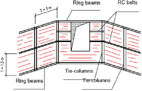
Da-hai LIU et al. [8] investigated and informed that some brick masonry structures failed during earthquake intensity of 10 degrees in MM scale and they showed the introduction of RC belt, RC ring beams and tie columns in masonry building and effects of the same against collapse was observed on exterior walls. In confined masonry buildings, they placed the RC tie-columns at every intersection of the longitudinal and transverse walls and the intermediate
tie-columns were placed at the spacing of 2 to 3m along the longitudinal and transverse walls. Ring beams were placed at every floor level along with all the walls, the horizontal reinforced concrete belts were placed at the spacing of 1.0 to 1.5m in the interior walls and at the spacing of 0.5 to 0.75m in the exterior walls. One layer or two layers of the reinforced concrete belt may be placed in the interior load-bearing walls. It was located at 1/2nd or 1/3rd and 2/3rd story height respectively. If a
window comes in between than RC belts should be placed on the walls between windows. Experimental result of the study showed that the diagonal cracks across the wall were prevented, the cracks on the wall surface were restricted within the area between the belts.
Fig. 3 Introduction of RC belts, columns and beams
Da-hai LIU et al. [8]
IS:1893-2002 for seismic design. Four outriggers were installed at 0.2H, 0.4H, 0.6H and 0.8H with central core and 7 different combinations of outrigger material, bracing type and core were taken. Both steel and concrete outriggers were installed in different models and results were noted down. It was seen from the results that concrete core and concrete outrigger X braced shaped gave out the displacement and drift of 80.3mm and 0.000703 which were found to be minimum as compared to all other combinations. Also, the maximum base shear was seen to be 4419 kN for the same combination. It was noted too, that the X braced system showed better results than V braced system for all the combination. For time history analysis, the models having a concrete core and concrete outriggers showed less variation than compared to that of steel. A. Suresh et al. [10] worked on the analysis of a model of a 44 storey Moment resisting RC frame building by Equivalent static method, Response Spectrum method as well as Dynamic Wind Analysis using software ETABS in accordance with IS codes. In this study, they modelled the outrigger with different types of bracing such as X, V and inverted V type of bracings. It was observed from the analysis that the 29.21% of top storey displacement and 26.64% of maximum story drift was controlled by providing X-braced outriggers. Also, the model with steel outrigger was found to be less effective in controlling displacement by 19.49% and for storey drift by 17.27% as compared with concrete outriggers.
Abdul Karim Mullah et al. [11] modelled four 20-storey RC regular and irregular (vertically) buildings each with and without outrigger with a central rigid shear
and showed the similar results in case of bracing on two sides.
Vijaya Kumari et al. [13] studied the behaviour of an RC 30-storey building against lateral displacement and inter-storey drift, using Finite element method ETABS. The model had been analysed for equivalent static and response spectrum method as per IS 1893: 2002. They implemented X, V and inverted V type of concrete belt truss at top and middle of the structure along with the shear core. And it was observed that the reduction in displacement was around 35% for RSM and 10% for ESM for X and inverted V type of belt truss.
Prajyot A. Kakde et al. [14] worked on the model of a 70-storey building to carry out the effects of the outrigger material. The model had been analysed for dynamic time history analysis, also wind analysis had been studied in accordance with IS 875 part III. The study was conducted using 4 outriggers at 0.25H, 0.5H, 0.75H and H (case 1) of the structure height and the same study was done by using the outriggers at 0.2H, 0.4H, 0.6H and 0.8H (case 2) for concrete and steel outriggers. The case 2 performed better than case 1. For wind analysis, the reduction in deflection was 26% and 29.7% for concrete and steel outriggers respectively for case 2. Whereas for time history analysis, the reduction in deflection was 15.15% and 17.51% for concrete and steel outrigger respectively for case 2.
Raad Abed Al-Jallal Hasan [15] carried out the comparative study between beam outrigger-belt truss and wall outrigger-belt wall on a model of a 30-storey building. It was a double outrigger structure with the first outrigger at 1/3rd H and the second outrigger at
2/3rd H of the structure. The model had been analysed
for response spectrum method using software ETABS. It was seen from the results that the drift, displacement and the base moment in the structure with wall outrigger were found to be lesser than in structure with beam outrigger.
Kishan P. Solanki et al. [16] worked on a model of a 50 story RC building to investigate about the effect of different depths of outrigger. And concluded that, the maximum story displacement reduced from 425mm without outrigger to 342mm after providing full story deep outrigger. Decrease in the depth of the outrigger to 2/3rd, 1/3rd and 1/2nd of the story height reduced the
percentage reduction of lateral displacement and story drift up to 3%-4% and 5%-6% respectively in comparison with outrigger depth of full story height. Abhishek Arora et al. [17] carried out an investigation on outrigger system on a model of a 30-storey building with varying depths of outrigger. In which they provided the outrigger at top with 2/3rd, 1/3rd and full
story height of outrigger. And it was observed that when full story deep outrigger was used, the story drift was found to be 0.67 which was minimum. The values of story drifts were found to be 0.71, 0.76 and 1 for outrigger with 2/3rd, 1/3rd of story depth and without
outrigger respectively.
mid height, the reduction in displacement for outrigger with full storey height, 2/3rd and 1/3rd of storey height
were 36.96%, 32.26% and 16.49% respectively as compared to without outrigger.
M. R. Suresh et al. [19] made an attempt to evaluate the seismic performance of a 30-storey RC structure with central core wall with and without outrigger by varying the relative stiffness, in ETABS software. The relative stiffness was varied by considering the ratio of depth of outrigger beam to depth of conventional beam (do/d) from 1 to 5 with an interval of 1. Outriggers were placed at different locations such as 0.25H, 0.5H, 0.75H and H and analysis was carried out using equivalent static method and response spectrum method in different zones. In all zones, the model with maximum relative stiffness i.e. 5 showed minimum deflection and inter-storey drift and maximum base shear as compared to all other models with relative stiffness of 1, 2, 3 and 4.
III.
DISCUSSIONS
Many researchers have worked on the effectiveness of steel outrigger but a few of them have highlighted the better performance of the concrete outrigger. Design strategies of some existing tall structures have been discussed wherein concrete outrigger or belt wall were used [3-8]. Cracks in the walls of a load bearing structure can be minimized by the application of one or two thin RC belt and RC columns. This can be done for building stories up to 10 floors. Concrete outrigger with belt truss showed 30.95% reduction in displacement whereas steel outrigger with belt truss showed 26.32% [9] which proves that the concrete
outrigger is more efficient in reducing the displacement than steel outrigger and hence validating [10-11, 13-15]. X concrete bracing and combine V steel bracing show minimal displacement as compared with all other types of concrete and steel bracings [12]. For wind analysis, the reduction in deflection was 26% and 29.7% for concrete and steel outriggers respectively [14]. The stiffness of structure increases as the depth of the outrigger increases [16-19].
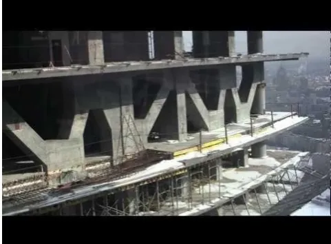
Fig. 4 Steel Belt truss
IV. CONCLUSIONS
The performance and implementation of proposed outrigger structural system are very much dependent on the number of factors such as its position, construction cost, construction time, bracing type and material etc. In this paper, implementation of concrete outrigger or belt wall in existing tall structures is discussed. It was seen that introduction of precast RC columns and RC belts to the existing building of up to 10 stories can minimize the length of the cracks on walls. X type of bracing is seen to be the most effective amongst all other types of bracing and which is followed by inverted V and combine V type of bracing. Also, concrete outriggers are proved to be more efficient in reducing lateral displacement of the structure than the steel outriggers. It is known that more the depth of outrigger beam, stiffer will be the structure but it may not be economical to increase the depth of outrigger to two or three stories and hence one storey deep outrigger may be provided on the refuge or mechanical floors to reduce the usage of space for outrigger. Also, the deflection can be reduced by increasing the size or dimension of the outrigger too [11]. In terms of deflection control, interior outrigger works better than exterior outrigger i.e. belt truss [10]. Steel outriggers are provided in steel frame building and for better results, RC outriggers should be provided in RC buildings.
V.
FUTURE SCOPEa. The usage of outrigger system on structures with irregular plan or buildings with vertical irregularity should be studied.
b. There’s deficiency of work on an actual
architectural plan.
c. Only some of the researchers have analyzed the model by non-linear method such as time history method in zone V.
d. Building models with height up to 100 floors can be made to study.
e. The modification in conventional outrigger system i.e. Virtual and Damped outrigger system can be implemented.
f. The effect of concrete outrigger and belt walls can be studied in different zones and on different soil. g. Optimum locations of outrigger beams could be
found for more than 3 outriggers or more than 3 belt trusses.
h. Necessity and effects of double and triple storey deep outrigger can be studied and compared with the two and three number of outriggers on a structure.
REFERENCES
[1] Ali Sherif S. Rizk, “Structural Design Of Reinforced Concrete Tall Buildings”, CTBHU
Journal, Issue 1, pp. 43-4, 2010
[2] Karan D. Sitapara, N.G. Gore, “Review On
Feasibility Of High Rise Outrigger Structural
System In Seismically Active Regions”
International Research Journal of Engineering and Technology, Vol. 03 Issue 07, pp.197-203, 2016
[3] Kwang Ryang Chung, Chulho Park, Do Hyun
Kim, “Design Considerations for concrete highrise Buildings”, International Journal of
Highrise Buildings Vol. 5 No. 3, 187-193, 2016 [4] John Merrick, Radu Bliuc, Mike Haysler, “Design
of a Composite Outrigger Structure for the Dubai
Tower, Doha”, Concrete Solutions 09
[5] Jong Soo Kim, “Challenges in Structural Design
of W-Project”, International Journal of Highrise
Buildings Vol. 3 No. 3, 199-204, 2014
[6] Ranjith Chandunni, Farshad Berahman, “The structural design of Almas Tower, Dubai, UAE”,
ICE, 2010
[7] Goman Wai-Ming Ho, “The Evolution of Outrigger Structural system in tall Buildings”,
International Journal of Highrise Buildings Vol. 5 No. 1, 21-30, 2016
[8] Da-hai LIU, Mao-zheng WANG, “Masonry
Structures Confined with Concrete Beams and
Columns”, 12 WCEE, 2000
[9] Errol Dsouza, Dileep Kumar U., “A Study on
Outrigger System in Seismic Response of Tall Structures by Non-Linear Analysis”, Vol. 6, Issue
8, 2017
[10] A. Suresh, B. Bhanupriya, A. Ramakrishnaiah,
“Influence of Concrete and Steel outrigger and
belt truss in high rise Moment Resisting Frames”,
International Research Journal of Engineering and Technology, Vol. 04, Issue 11, 2017
[11] Abdul Karim Mullah, Srinivas B. N., “A Study on
Outrigger System in a Tall RC Structure with
Steel Bracing”, International Journal of
Engineering Research and Technology, Vol. 4, Issue 7, 2015
[12] Bhosle Ashwini Tanaji, Shaikh A. N., “Analysis of
Reinforced Concrete Building with Different Arrangement of Concrete and Steel Bracing
system”, IOSR Journal of Mechanical and Civil
Engineering (IOSR-JMCE), Vol. 12, Issue 5, 2015),
[13] Vijaya Kumari Gowda M. R., Manohar B. C., “A
Study on Dynamic Analysis of tall Structure with
Belt Truss System for Different Siesmic Zones”,
International Journal of Engineering Research and Technology, Vol. 4, Issue 8, 2015
[14] Prajyot A. Kakde1, Ravindra Desai, “Comparative
Study of Outrigger and Belt Truss Structural
System for Steel and Concrete Material”,
International Research Journal of Engineering and Technology, Vol. 04, Issue 05, 2017
[15] Raad Abed Al-Jallal Hasan, “Behavior of Beam and Wall Outrigger in High -Rise Building and
their Comparison”, International Journal of Civil,
Structural, Environmental and Infrastructure Engineering Research and Development, Vol. 6, Issue 1, 2016
[16] Kishan P. Solanki, Pradeep Pandey, “Behaviour of Outrigger System on High Rise Structure by
Varying Outrigger Depth”, Journal of Emerging
Technologies and Innovative Research, Vol. 4, Issue 04, 2017
[17] Abhishek Arora, Ravi Kumar, “Strengthening of High Rise Building with Outrigger System”,
IJSRSET, Vol. 2, Issue 3, 2016
[18] Srinivas Suresh Kogilgeri, Beryl Shanthapriya, “A
Study on Behaviour of Outrigger System on High Rise Steel Structure by Varying Outrigger
Depth”, International Journal of Research in
Engineering and Technology, Vol. 4, Issue 7, 2015
[19] M. R. Suresh, Pradeep K. M., “Influence of
Outrigger System in RC Structures for Different
Seismic Zones”, International Journal for