© 2016 IJSRSET | Volume 2 | Issue 3 | Print ISSN : 2395-1990 | Online ISSN : 2394-4099 Themed Section: Engineering and Technology
A Study on the Effect of Fly Ash on Hybrid Fibre Reinforced Concrete
A Paul Makesh1, Vellingiri Anusuya
21
Assistant Professor, Wolkite University, Wolkite, Ethiopia
2
Lecturer, Wolkite University, Wolkite, Ethiopia.
ABSTRACT
In the civil engineering practice concrete is the most common construction material that is used for construction. Since the concrete can be casted in any desirable shape, it has replaced the traditional constructional technique that used stones and brick masonry. Steel Structures results in the failure due to the corrosion of the steel by the salt and also a periodical maintenance and repairing are needed to enhance the life cycle of those civil structures. The present study is to investigate the effect of two different types of fibres on fly ash based concrete in terms of strength and flexural properties. The mechanical properties are given in terms of compressive, splitting tensile strength and flexural tests of hybrid fibre reinforced concrete with different percentages of fly ash. The use of hybrid fibres changes the mechanical properties of concrete specimens and prevents the settlement and shrinkage cracks. The steel fibres act as micro-bridges throughout the cracked concrete, transfer cracking stresses over a crack from one side to the other. The analysis includes the study in improving the different mechanical properties of hybrid fibre reinforced concrete.
Keywords: Flexural Properties, Hybrid Fibre, Mechanical Properties, Reinforced Concrete.
I.
INTRODUCTION
Types of Fibres
Large variety of fibre materials have been developed in FRC that are available with various sizes and shapes. These find a very great use in the construction industry. A conventional numerical parameter describing a fibre is its aspect ratio, defined as the fibre length divided by diameter (or equivalent diameter in the case of non-round fibres). Typical aspect ratios are used in the range from 30 to 150 for length dimensions of 6.0 to 76.0mm.
Steel Fibre
Steel fibres have been used in the concrete technology since the early 1900s. The early fibres were round, Smooth and were cut or chopped to the required lengths. The use of straight, smooth fibres has largely disappeared and modern fibres either with rough surfaces or hooked ends are manufactured from drawn
processes. Steel fibre contents of up to 25% by volume have been obtained in slurry-infiltrated fibre concrete. Similarly, it is reported that the elastic modulus in compression and modulus of rigidity in torsion are no different before cracking when compared with plain concrete tested under similar conditions. It has been reported that steel-fibre reinforced concrete, because of the improved ductility, could find applications where impact resistance is important. Fatigue resistance of the concrete is reported to be increased by up to 70%.Dramix is a cold drawn steel wire fibre with hooked ends for optimum anchorage.
Polypropylene Fibre
Polypropylene is a synthetic hydrocarbon polymer, the fibre of which is made by drawing the material through a die. Polypropylene fibres are produced as continuous mono-filaments, with the circular cross section that can be chopped to required lengths or fibrillated films or tapes of rectangular cross section. This possesses poor bond characteristics with cement matrix, a low melting point, high combustibility and a relatively low modulus of elasticity. Long polypropylene fibres are difficult to mix because it wraps around the leading edges of mixer blades. These are tough and have low tensile strength. Monofilament polypropylene fibres have inherent weak bond with the cement matrix because of their relatively small specific surface area. Fibrillated polypropylene fibres are slit and expanded into an open network thus offering a larger specific surface area with improved bond characteristics. Polypropylene fibres have been used successfully with hand-packing fabrication techniques. But volumes of 0.1% of 50-mm fibre in concrete have been reported to have caused a slump loss of 75 mm. Polypropylene fibres have been reported to reduce unrestrained plastic and drying shrinkage of concrete.
II.
METHODS AND MATERIAL
1. Literature Survey
Sayad Mohamad (1991) investigated the flexural response of HYFRC. Up to three different types of fibres such as steel / polypropylene macro fibres and carbon/polypropylene/steel micro fibres were combined in each mix hybridization. The compressive strength of the concrete was around 55-60 MPa. The purpose of the
research was to investigate the influence of various hybrid fibre combinations on fresh properties of concrete and on mechanical properties including compressive strength and toughness in bending. Measuring the VeBe time for each and every mix assessed the workability of FRC/HYFRC; cylindrical specimens were used to determine the compressive strengths. Finally, synergistic effects between fibres were observed with enhanced performance of the material over the wider range of deflections.
Chunxiang Qian et al (1999) investigated a research on polypropylene fibres and three sizes of steel fibres reinforced concrete. The total fibre content ranges from 0% to 0.95% by volume of concrete. There search results show that there was a positive synergy effect between large steel fibres and polypropylene fibres on the load-bearing capacity and fracture toughness in the small displacement range. But this synergy effect disappears in the large displacement range. The large and strong steel fibre is better than soft polypropylene fibre and small steel fibre in the aspect of energy absorption capacity in the large displacement range.
Mustafa sahamaran et al (2004) conducted a study on the fresh and mechanical properties of a fibre reinforced self-compacting concrete incorporating high-volume fly ash that does not meet the fineness requirements of ASTM C 618. A poly carboxylic-based super plasticizer was used in combination with a viscosity modifying admixture. In mixtures containing fly ash, 50% of cement by weight was replaced with fly ash. Two different types of steel fibres were used in combination, keeping the total fibre content constant at 60 kg/m3. Slump flow time and diameter, V-funnel, and air content were performed to assess the fresh properties of the concrete.
Compressive strength, splitting tensile strength, and ultrasonic pulse velocity of the concrete were determined for the hardened properties. The results indicated that high-volume coarse fly ash can be used to produce fibre reinforced self-compacting concrete, even though there is some reduction in the concrete strength because of the use of high-volume coarse fly ash.
were prepared with 0 wt%, 15 wt%, and 30 wt% of fly ash, at 0 vol.%, 0.5vol.%, 1.0 vol.% and 1.5 vol.% of fiber, respectively. After being cured under the standard conditions for 7, 28, 90 and 365 d, the specimens of each mixture were tested to determine the corresponding compressive and flexural strengths. The parameters such as the amounts of cement, fly ash replacement, sand, gravel, steel fibre and the age of samples were selected as input variables, while the compressive and flexural strengths of the concrete were chosen as the output variables. The back propagation learning algorithm with three different variants, namely the Levenberg-Marquardt (LM), scaled conjugate gradient (SCG) and Fletcher-Powell conjugate gradient (CGF) algorithms were used in the network so that the best approach can be found. The results obtained from the model and the experiments were compared, and it was found that the suitable algorithm is the LM algorithm. Furthermore, the analysis of variance (ANOVA) method was used to determine how importantly the experimental parameters affect the strength of these mixtures.
Fuat Ko Ksal et al (2007) experimentally investigated on the mechanical properties of concrete specimens produced by using silica fume and steel fibre. The main objective of this work was to obtain a more ductile high strength concrete produced by using both silica fume and steel fibre. Two types of steel fibre with aspect ratios (fibre length/fibre diameter) of 65 and 80 were used in the experiments and volume fractions of steel fibre were 0.5% and 1%. Additions of silica fume into the concrete were 0%, 5%, 10% and 15% by weight of cement content. Water/cement ratio was 0.38 and the reference slump was 120 ± 20 mm. Slump test for workability, air content and unit weight tests were performed on fresh concretes. Compressive strength, splitting tensile strength and flexural strength tests were made on hardened concrete specimens. Load–deflection curves and toughness of the specimens were also obtained by flexural test performed according to ASTM C1018 standards. Flexural tests on beam specimens were achieved using a closed loop deflection-controlled testing machine. The use of silica fume increased both the mechanical strength and the modulus of elasticity of concrete. On the other hand, the addition of steel fibre into concrete improves toughness of high strength concrete significantly. As the steel fibre volume fraction increases, the toughness increases, and high values of aspect ratios give higher toughness. The toughness of
high strength steel fibre concrete depends on silica fume content, the fibre volume fraction and the fibre aspect ratio.
Cengiz Duran Atis et al (2007) carried out a study on the properties of concrete containing fly ash and steel fibres. Properties studied include unit weight and workability of fresh concrete and compressive strength, flexural tensile strength, splitting tensile strength, elasticity modulus, sorptivity coefficient, drying shrinkage and freeze–thaw resistance of hardened concrete. Fly ash content used was 0%, 15% and 30% in mass basis, and fibre volume fraction was 0%, 0.25%, 0.5%, 1.0% and 1.5% in volume basis. The laboratory results showed that steel fibre addition, either into Portland cement concrete or fly ash concrete; improve the tensile strength properties, drying shrinkage and freeze–thaw resistance. However, it reduced workability and increase sorptivity coefficient. Although fly ash replacement reduces the strength, it improves workability, reduces drying shrinkage and increases freeze–thaw resistance of steel fibre reinforced concrete. The performed experiments show that the behaviour of fly ash concrete is similar to that of Portland cement concrete when fly ash is added.
show that incorporating polypropylene fibres improves mechanical properties. The addition of silica fume facilitates the dispersion of fibres and improves the strength properties, particularly the impact resistance of concretes. It is shown that using 0.5% polypropylene fibre in the silica fume mixture increases compressive split tensile and flexural strength and especially the performance of concrete under impact loading.
2. Experimental Program
General
This chapter presents the details of materials, mix design of the concrete and details casing of test specimens. The materials used for the study are cement, fine aggregate, coarse aggregate, fly ash, polypropylene fibres, and bundled hooked-end steel fibres have been described. The materials used for the study are Ordinary Portland Cement (OPC), Coarse aggregate, Fine aggregate, Water, Bundled hooked end steel fibres, Polypropylene fibres, Fly ash.
Ordinary Portland Cement
Ordinary Portland cement (OPC) is by far the most important type of cement. Early there was only one grade of OPC which was governed by IS 269-1976. After 1987 higher grade cements were introduced in India.
The OPC is classified as 33 grade, 43 grade and 53 grade depending upon the strength of the cement when tested as per IS 4031-1988. The properties of cement like consistency, initial setting time, final setting time and specific gravity were studied and the obtained results were shown in Table I.
Table I. Properties of Ordinary Portland Cement
TEST RESULT AS PER IS
4031-1998
Consistency 53 Initial setting
time 90 min
Not less than 30 min.
Final setting
time 5 hours
Not more than 600 min.
Specific
gravity 3.14
Aggregates
Aggregates are the important constituents in concrete that reduces shrinkage and economic. Earlier, aggregates were considered as chemically inert materials that are chemically active. The aggregates occupy 70–80 per cent of the volume of concrete and cause impact on various characteristics and properties of concrete.
Cement is the factory made standard component in concrete. Other ingredients, namely, water and aggregates are natural materials that can vary to any extent. The properties of Fine aggregate and Coarse aggregate are given in Table II and III respectively.
Table II. Properties of Fine Aggregate
TEST RESULT AS PER IS
383-1970
Fineness
Modulus 2.82 Medium Sand Specific
Gravity 2.70 2.55
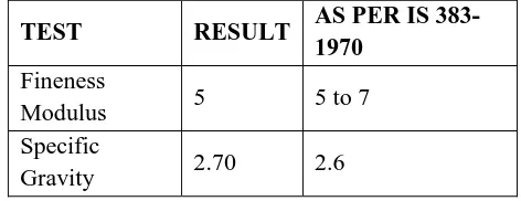
TABLE III. Properties of Coarse Aggregate
TEST RESULT AS PER IS
383-1970
Fineness
Modulus 5 5 to 7 Specific
Gravity 2.70 2.6
3. Casting of Specimens
sample, it becomes very necessary to have a uniform and smooth surface. The ends of all cylindrical test specimens are capped. The hybrid fibre reinforced concrete at volume fraction of 0.5% & 1% is prepared for different combination. The completed moulding is to be stored in the vibration free place within the moist air of at least 90% relative humidity and at a temperature of 27° ± 2° C for 24 hours. After this the specimens are removed from the mould with a mark and immediately submerged in clean, fresh water for testing.
4. Test Procedures
The specimens are subjected to the following tests.
A. Compressive Strength Test (Cubes-150x150x150mm)
B. Splitting Tensile Strength Test (Cylinder -150x300mm)
C. Flexural Strength Test (Prism- 100x100x500mm)
Compressive Strength Test
The compressive strength test is carried out as per IS 516 – 1968. The specimens of size 150mm cube are caste with volume fraction of 0.5 and 1.0 % with two types of fibre. The test is carried out for 28 days and test results are compared with control concrete specimens. Compression testing machine of capacity 1000kN is used for the test. At least three specimens, preferable from different batches are taken for testing at selected age. Specimens stored in water should be tested immediately while they are in the wet condition. In the case of cubes the specimen should be placed in the machine in such a manner that the load is applied to the opposite side of the cubes as cast, that is not at the top and bottom. The load should be applied without shock, to be increased continuously at a rate of approximately 140 kg/cm2/min until the resistance of the specimen breaks down. The measured compressive strength of the specimen shall be calculated by dividing the maximum load applied to the specimen during the test by the cross-sectional area. Average of three values shall be taken as the representative of the batch provided the individual variation is not more than ± 15 percent of the average. Otherwise repeat tests shall be made. The failure load was noted and the compressive strength of the specimen is calculated by the equation given below.
MPa Specimen of
Section Cross of Area
Load Ultimate Strength
e
Compressiv
Splitting Tensile Strength Test
This test is carried as per IS 5816-1999 at an age of 28 days of the test specimens. The ages shall be calculated from the time of the addition of water to the dry. The dry specimen is to be kept in water for 24 hour before they taken for testing. The surface water, projecting fins and grit shall be wiped off the specimens are removed from the surface. Central lines shall be drawn on the two opposite side of cylinder using any suitable procedure and to ensure that they are in the same axial plane. The mass and dimensions of the specimen shall be noted before testing. The test specimen shall be placed in the centring jig with packing strip and/or loading pieces carefully positioning along the top and bottom of the plane of loading of the specimen. The jig shall then be placed in the machine so that the specimen is located centrally. For a cylindrical specimen the load is applied without shock and increased continuously at a nominal rate within the range 1.2 to 2.4 N/ (mm2/min). This is maintained until failure. The appearance of concrete and any unusual features in the type of failure shall also be noted.
Flexural Strength Test
This test is carried out as per IS 516-1968. A concrete prism of size 500x100x100mm is casted. The test is carried out at the age of 28 days curing period for both control and HYFRC specimens. The test was carried out in a Universal Testing Machine of capacity 400kN. The permissible error is not greater than ± 0.5 percent of the applied load and not greater than ± 1.5 percent of the applied load for commercial type of use.
The bed of the testing machine shall be provided with two steel rollers, 38 mm in diameter, on which the specimen is to be supported, and these rollers shall be so mounted at a distance from centre to centre 60 cm for 15.0 cm specimen and 40 cm for 10.0 cm specimens. The load shall be applied through two similar rollers mounted at the third points of the supporting span that is spaced at 20 or 13.3 cm centre to centre. The load shall be divided equally between the two loading rollers, and all rollers shall be mounted in such a manner that the load is applied axially and without subjecting the specimen to any restraints.
Test specimens are stored in water at a temperature of 24° to 30°C for 48 hours before testing shall be tested immediately on removal from the water whilst under wet condition. The dimensions of each specimen shall be noted before testing. No preparation of the surfaces is required. The bearing surfaces of the supporting and loading rollers shall be wiped clean. Any loose sand or other materials are removed from the surfaces of the specimen to avoid contact with the rollers. The specimen is then placed in the machine in such a way that the load shall be applied to the uppermost surface with 20.0 cm or 13.3 cm apart. The axis of the specimen is carefully aligned with the axis of the loading device. Packing is avoided between the bearing surfaces of the specimen and the rollers. The load shall be applied without shock and is increased continuously at the rate of approximately 7 kg/sq cm/min for a load of 400 kg/min for the 15.0 cm specimens and at a rate of 180kg/min for the 10.0 cm specimens.
The load shall be increased until the specimen fails, and the maximum load applied to the specimen during the test shall be recorded. The appearance of the fractured faces of concrete and any unusual features are recorded. The flexural strength of the specimen is expressed as the modules of rupture fb which, if „a‟ equals the distance
between the line of fracture and the nearer support, measured from the centreline of the tensile side of the specimen in cm is calculated to the nearest 0.5 kg/sq cm as follows.
MPa f
Strength,
Flexural b 2 bd
PL
when „a‟ is greater than 20.0 cm for 15.0 cm specimen and greater than 13.3cm for a 10.0 cm specimen
MPa 3 f Strength,
Flexural b 2
bd Pa
Flexural Toughness
The reason of adding fibres to concrete is to improve the energy-absorbing capacity of the matrix. This can be evaluated by determining the area under the stress-strain curve or by the load-deformation behaviour. In the case of blending, the area under the load-deflection curve is used to estimate the energy-absorbing capacity or toughness of the material. Increased toughness also means improved performance under fatigue, impact, and impulse loading. The toughness index is used to measure the composite‟s ability that undergoes larger deformations before failure. In the ASTM C1018 procedure, the deformation is taken as the area under the load deflection curve up to the first crack. The first crack is assumed to occur at the point where the load - deflection curve deviates from the initial linear portion as shown in fig 2.
Figure 2. Flexural Toughness as per ASTM C1018
Three level deflection namely 3δ, 5.5δ and 10.5δ are suggested. The term δ is the deflection up to first crack. Deflection values greater than 10.5δ can also be considered for composites that carry considerable loads at large deflection. The three suggested indices are called I5, I10 and I20, which are defined by the following
equation. If δ is the deflection at the first crack,
Area OAB = Toughness corresponding to a deflection of δ, (Tδ) Area OACD = Toughness corresponding to a deflection of 3δ, (T3δ) Area OAEF = Toughness corresponding to a deflection of 5.5δ (T5.5δ)
Area OAGH = Toughness corresponding to a deflection of 10.5δ (T10.5δ)
Where δ = the deflection at the linear elastic limit
Toughness Index, I5 – The number obtained by dividing
Toughness Index, I10 – The number obtained by dividing
the area up to 5.5 times the first crack deflection by the area up to the first crack of the load deflection curve. I10 = Area OAEF/Area OAB
Toughness Index, I20 - The number obtained by dividing
the area up to10.5 times the first crack deflection by the area up to the first crack of the load-deflection curve. I20 = Area OAGH/Area OAB
In addition to these three indices, the ratios I10/I5, I20/ I5
are also used to evaluate the toughness at large deflections. Higher ratios represent better performance.
III.
RESULTS AND DISCUSSION
1. Results of Compressive Strength
The results of compressive strength of concrete for volume fraction of 0.5% and 1% of hybrid fibre with different percentage of fly ash are shown in Fig.3 and Fig 4 respectively.
Figure 3. Compressive Strength of Concrete with 0.5% of HYFRC with Flyash
Figure 4. Compressive Strength of Concrete with 1% of HYFRC with Flyash
2. Results of Splitting Tensile Strength
The results of Splitting Tensile strength of concrete for volume fraction of 0.5% and 1% of hybrid fibre with
different percentage of flyash are shown in Fig 5 and Fig 6 respectively.
Figure 5. Splitting Tensile Strength of Concrete with 0.5% of HYFRC with Flyash
Figure 6. Splitting Tensile Strength of Concrete with 1% of HYFRC with Flyash
3. Results of Flexural Tensile Strength
The results of Flexural Tensile strength of concrete for volume fraction of 0.5% and 1% of hybrid fibre with different percentage of flyash are shown in Fig 7 and Fig.8 respectively.
Figure 7. Flexural Tensile Strength of Concrete with 0.5% of HYFRC with Flyash
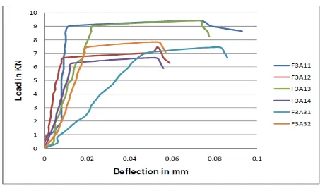
4. Results of Flexural Toughness
The toughness of fibre-reinforced concrete can be considered as their energy absorption capacity, which is usually characterized by some portion of the area under the load-deflection curve obtained during flexure test for the two different fibres as shown in Fig.9 Fig.10 and Fig.11 respectively. The flexural toughness indices may be calculated as the ratio of the area under the load- deflection curve for the fibre reinforced concrete to specified endpoints, to the area up to first-crack load, as shown in ASTM C 1018.
Figure 9. Load – Deflection Curve for Specimens on 5% of Flyash
Three indices defined in ASTM C 1018 are obtained by dividing the area under the load-deflection curve, determined at a deflection that is a multiple of the first-crack deflection, by the area under the curve up to the first-crack. I5 is determined at a deflection 3 times the first-crack deflection, I10 is determined at 5.5 times the first-crack deflection. These indices increased their values with increasing volume fraction.
Figure 10. Load – Deflection Curve for Specimens on 10% of Flyash
Figure 11. Load – Deflection Curve for Specimens on 10% of Flyash
IV.
CONCLUSION AND SCOPE FOR FUTURE
The following conclusions were drawn on the experimental study:
Volume fraction of 0.5% on10% of fly ash shows a considerable enhancement in compressive strength and Volume fraction of 1% on 5% of flyash shows a significant improvement in splitting tensile strength, Volume fraction of 1% on 10% of flyash shows a significant improvement in flexural strength than the control concrete. The compressive strength for volume fraction of 0.5% on 10% of fly ash exhibits a better performance when compared with other combination of fibres. The Volume fraction of 0.5% on10% of flyash shows a significant increase in strength of 51.91% when compared with control concrete. The splitting tensile strength for volume fraction of 1% on 5% of fly ash is better compared to volume fraction of 0.5% on 10% of fly ash and volume fraction of 1% on 10% of flyash. The range increases from 38.90% to 108.35% when compared with control concrete. The flexural strength of volume fraction of 1% on 10% of flyash is better compared to volume fraction of 1% on 5% of fly ash and volume fraction of 0.5% on10% of fly ash. The range increases from 4.09% to 76.16% when compared with control concrete. The flexural toughness indices values of all fibre concrete were higher than of control concrete. Volume fraction of 0.5% on 5% of fly ash combination only shows the best results in Flexural Toughness Indices compared to other combinations. Finally performed experiments shows that the behaviour of flyash concrete is similar to that of Portland cement concrete when flyash is added. The following works need to be carried out to exploit the full potential of fibre reinforced concrete:
Performance of fibre in high strength concrete can be studied. Bonding performances of concrete can be studied.
V.
REFERENCES
[1] Mahmoud Nili and Afroughsabet V., 2009, “The effects of silica fume and polypropylene fibers on the impact resistance and mechanical properties of concrete”, Journal of Construction and Building Material, Volume 24, Issue 6, pp. 927-933.
[2] Zhimin Wu, Yunguo Zhang, Jianjun Zheng and Yining Ding., 2009, “An experimental study on the workability of self-compacting lightweight concrete”, Journal of Construction and Building Material,Volume 23, Issue 5, May 2009, Pages 2087–2092.
[3] Fuat Koksala, Fatih Altunb, Ilhami Yigitc and Yusa Sahina., “Combined effect of silica fume and steel fiber on the mechanical properties of high strength concretes”, Journal of Construction and Building Materials, Volume 22, Issue 8, August 2008, Pages 1874–1880