Extensible Multiple Spanning Tree Protocol for Virtual
eXtensible LAN
Seok Weon Seo, Seong Mun Kim, Sung Gi Min
*High-Speed Communications Lab., Department of Computer and Radio Communication Engineering, Korea University, Seoul, Republic of Korea.
* Corresponding author. Tel.:+82-2-3290-3640; email: [email protected] Manuscript submitted February 15, 2015; accepted June 15, 2015.
doi: 10.17706/ijcce.2016.5.2.120-129
Abstract: Virtual eXtensible LAN (VXLAN) is a Layer 2 overlay scheme over a Layer 3 to solve the scalability problems of Virtual LAN (VLAN). VXLAN utilizes IP multicast to broadcast a frame to hosts in a VXLAN segment which has an independent broadcast domain. The VXLAN segment is mapped into a multicast group based on a multicast tree which ensures a loop-free topology. However, VXLAN depends on IP multicast because all devices have to support IP multicast. In addition, IP multicast requires a large amount of network resources to maintain multicast trees which are built per the multicast group. In this paper, the proposed scheme replaces IP multicast. It is extended from Multiple Spanning Tree Protocol (MSTP), and provides the spanning tree to broadcast a frame and to prevent a loop topology in VXLAN. The IP multicast dependency is removed and the number of spanning trees is reduced by taking the advantage of MSTP that constructs a spanning tree per an instance. It also provides interoperability with VLAN by using a typical spanning tree algorithm.
Key words: IP multicast, MSTP, and VXLAN.
1.
Introduction
Local Area Network (LAN) is a computer network that interconnects hosts within a limited area [1]. LAN has a single broadcast domain that physically connects to hosts, and utilizes Spanning Tree Protocol (STP) to guarantee a loop-free topology in a Layer 2 network [2]. According to increase the number of hosts which are connected to a single broadcast domain, network bandwidth is wasted because broadcast traffic such as Address Resolution Protocol (ARP) request increases.
Virtual LAN (VLAN) is proposed to overcome the limitation of LAN such as a single broadcast domain in IEEE 802.1Q [3]. In VLAN, a single broadcast domain is logically partitioned to create multiple independent broadcast domains over a physical network. Each VLAN has the features similar to typical LAN, and hosts are configured into the same group even if they are not physically located in the same LAN. VLAN membership is configured by VLAN tagging in a bridge and supports up to a maximum of 4096. VLAN uses Per VLAN Spanning Tree (PVST) [4] proposed by Cisco or Multiple Spanning Tree Protocol (MSTP) defined in IEEE 802.1s [5] to ensure a loop-free topology in a Layer 2 network.
million VXLAN segments because VXLAN Network ID (VNI) space is 24 bits.
VXLAN uses IP multicast to extend a single broadcast domain to multiple broadcast domains more than VLAN, to manage the members of the VXLAN segment, and to provide a loop-free topology. Each VXLAN segment has an independent broadcast domain which is mapped into a multicast group. A broadcast frame is sent out to the members of the multicast group. Each multicast group is managed based on the multicast tree which is maintained by using multicast routing protocols such as Core Based Trees (CBT) [7] and Protocol Independent Multicast-Sparse Mode (PIM-SM) [8].
However, the use of IP multicast has some limitations in VXLAN [9]. First, VXLAN depends on IP multicast because broadcast communication and group management are performed based on multicast tree, and all devices have to support IP multicast to operate VXLAN. Second, IP multicast causes processing overheads and requires network resources to manage multicast trees which are built per the multicast group. CBT is one of multicast routing protocols, and it constructs a single multicast tree per a multicast group. The number of maintained multicast trees can increase up to a maximum of 16 million according to increase the number of VXLAN.
In this paper, Extensible Multiple Spanning Tree Protocol (ExMSTP) is proposed to overcome the limitations of the use of IP multicast. ExMSTP is extended from MSTP, and the IP multicast dependency can be removed since ExMSTP replaces IP multicast. ExMSTP reduces the number of spanning trees due to the feature of MSTP which constructs a spanning tree per an instance. It also supports interoperability with VLAN by using a typical spanning tree algorithm.
2.
Related Works
2.1.
Multiple Spanning Tree Protocol
PVST [4] and MSTP [5] are used to guarantee a loop-free topology and to provide the efficient load balance for multiple VLAN segments. PVST constructs an independent spanning tree per a VLAN segment. However, if the number of VLANs increases, a network has to handle pretty much loads to maintain a spanning tree per the VLAN segment and the network topology is more complicated. Unlike PVST, MSTP constructs a spanning tree per an instance which is mapped to a group of multiple VLAN segments. Thus, MSTP can reduce network resources to maintain spanning trees compared to PVST [10].
Bridge
RP: Root Port DP: Designated Port BP: Blocked Port
RP DP BP
MSTIs Root
- Region Name : Region 3 - Revision Number : 1 - VLANs-to-Instance Table Region 1
VLAN ID 10-20
...
Instance 1 ...
1 2
MSTI 0 (IST)
Bridge
Bridge
BP
Region 2
Bridge
Region 3
DP RP
1 2
3 MSTI 1
DP DP
RP RP
DP
DP DP
RP RP
DP RP RP
BP BP
BP BP BP BP
CST IST
Redundant link CIST Root
CIST Regional Root
Bridge
Bridge Bridge Bridge
3
Bridge
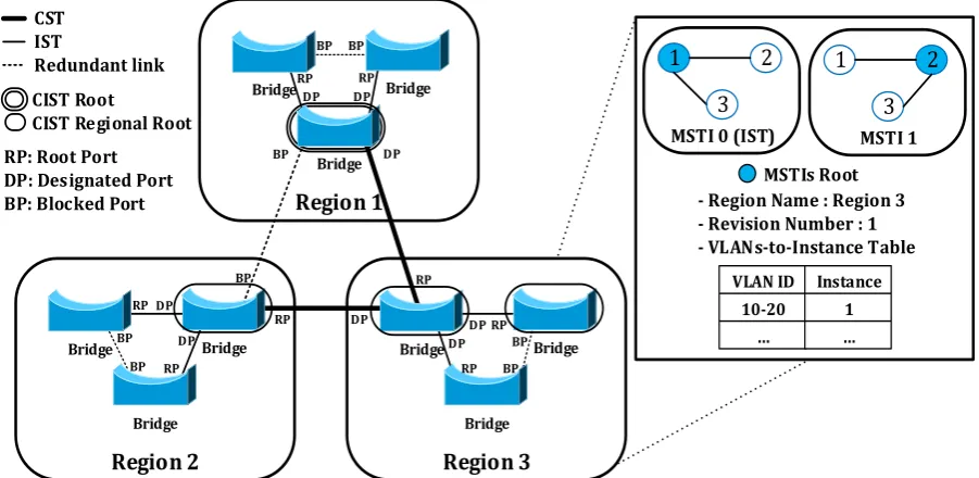
MSTP partitions a Layer 2 network into multiple regions. Bridges in the same region have the same MST region configuration. When the network topology is initialized by MSTP, the bridges exchange a special frame, called Bridge Protocol Data Units (BPDU), which includes information to construct a spanning tree such as bridges identifier, root identifier, root path cost, and instance information. MST Configuration ID in BPDU has region information such as region name, revision number, and a digest of the VLANs-to-Instance table [11]. Each bridge compares a received region information to own region information. If the MST Configuration ID is matching, the bridges are bound to the same region.
MSTP constructs a Common and Internal Spanning Tree (CIST) and Multiple Spanning Tree Instance (MSTI) [5] as shown in Fig. 1. The CIST consists of a Common Spanning Tree (CST) which connects each region and an Internal Spanning Tree (IST) which is mapped to the instance 0 in each region. The IST represents the each region, and only receives and sends all frames including BPDU to the CST. The MSTIs construct an independent spanning tree per an instance that is mapped to a group of multiple VLANs in a region, and supports up to a maximum of 64. Unlike the IST, MSTIs do not interwork with the outside of the region [11]. Instead, the instance information is added to a BPDU which is carried by IST.
When spanning trees are constructed by MSTP, each root bridge is selected for each spanning tree. A bridge which has a bridge identifier of the lowest priority in the entire network is elected as a CIST root. Then, a bridge which has the least cost path to the CIST root bridge in each region becomes the CIST regional root [5]. The CIST regional root bridge is the root of the IST that connects all bridges in each region and communicates with outside. Each MSTI also elects own root bridge which has a bridge identifier of the lowest priority in each instance.
The role of the each port is assigned to connect to nodes according to the root path cost in each spanning tree. The root port exists only one, and it guarantees the lowest root path cost and forwards a frame to the root. The designated ports send out frames including BPDU to neighbor bridges. The blocked port is designated to prevent a loop.
2.2.
Virtual eXtensible LAN
VXLAN is proposed to extend a Layer 2 network over a Layer 3 through an UDP/IP tunnel. The Ethernet frame is encapsulated with additional headers such as VXLAN header, Outer UDP, Outer IP, and Outer Ethernet [6]. A VXLAN Tunnel End Point (VTEP) transmits the encapsulated frame through a VXLAN Tunnel Interface (VTI).
Router
VTEP
Router
Router Rendezvous Point
Bridge Bridge
Bridge
Multicast IP Addr. 224.0.2.0 (VNI 1000)
...
Membership VTEP1, VTEP2
... [IGMP Table]
VLAN ID 10
...
VNI 1000
... [VLAN ID-to-VNI Table]
[MAC Address-to-VTEP IP Address Table] VNI
1000 ...
MAC 32:51:20:00:00:01
...
VTEP 128.1.1.1
...
[Multicast Group-to-VNI Table] Multicast Group
224.0.2.0
…
VNI 1000
...
VTEP
VTEP
VTEP
Source Host
Remote Host
Broadcast Unicast(Response)
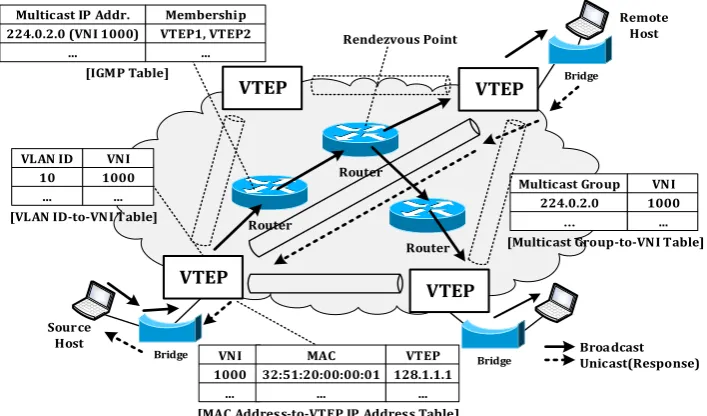
VXLAN uses IP multicast to extend a single broadcast domain to multiple broadcast domains more than VLAN and to broadcast a frame to remote hosts in the same VXLAN segment. A VXLAN segment has an unique VNI which is preconfigured, and is mapped into a multicast group. The mapping information is maintained in the each VTEP. The membership of multicast group is managed by using Internet Group Management Protocol (IGMP) [12], [13]. The multicast group is managed based on a multicast tree which is constructed by using multicast routing protocols such as CBT [7] and PIM-SM [8]. CBT constructs a single multicast tree per a multicast group and PIM-SM maintains a shared tree based on a root such as Rendezvous Point per the multicast group.
The packet flow in VXLAN based on IP multicast is shown in Fig. 2. When a host wants to communicate with a remote host, the host normally transmits an Ethernet frame to the remote host because the host is unaware of VXLAN. Then, the VTEP to which the host is attached, called a source VTEP (SVTEP), looks up the VNI related to the VLAN ID and maps the VLAN ID to the VNI. After mapping, the SVTEP looks up MAC address-VTEP IP address entry that contains the IP address of the destination VTEP (DVTEP) to which the remote host is attached, and the destination MAC address. If there is no matching entry, a broadcast frame is encapsulated with a VXLAN header and is transmitted to the members of the related IP multicast group according to the multicast tree.
When the DVTEP receives the broadcast frame, it decapsulates the VXLAN packet to get the original Ethernet frame. The DVTEP learns a SVTEP IP address and a host MAC address, and adds a new entry to its MAC address-to-VTEP IP address table. The DVTEP looks up the VLAN ID related to the VNI and maps the VNI to the VLAN ID, and the frame is handled in the related VLAN. After the remote host receives the broadcast frame, the remote host responses broadcast results. The response packet is sent to the SVTEP using unicast since the DVTEP already learns the host MAC address and the SVTEP IP address.
3.
Extensible Multiple Spanning Tree Protocol
ExMSTP is extended from MSTP to construct multiple spanning tree in VXLAN. ExMSTP provides a spanning tree to broadcast a frame, ensures a loop-free topology, and overcomes the limitations of IP multicast by taking the advantage of MSTP. The basic concept of ExMSTP is similar to typical MSTP. However, the major difference is that ExMSTP is only performed between Gateway Bridges (GB) with a VTEP, and all frames including BPDU are transmitted through an UDP/IP tunnel.
VXLAN Area VTEP Gateway Bridge VTEP Gateway Bridge VTEP Gateway Bridge Bridge Area 2 VTEP Gateway Bridge VTEP Gateway Bridge VTEP Gateway Bridge Area 1 Area 3 VTEP Gateway Bridge VTEP Gateway Bridge VTEP Gateway Bridge Extensible CST Extensible IST Redundant Tunnel ExCIST Root ExCIST Area Root
VTEP Gateway Bridge VLAN Segments Bridge VLAN Segments VTEP Gateway Bridge
- Area Name : Area 3 - Revision Number : 1 - VXLANs-to-ExMSTI table
Area Boundary
VXLAN 1000
ExMSTI 1 Redundant Tunnel ExMSTI 1 Root VTEP
Gateway Bridge To the ExCIST Root
VNI 1000-2000 ... Instance 1 ...
ExMSTP has the following features. ExMSTP provides mapping VXLAN segments to each instance using a VXLANs-to-ExMSTI table, and partitions an entire network into multiple areas which contain a spanning tree per an instance. ExMSTP also supports multiple forwarding paths and blocks unnecessary paths for a loop-free topology. ExMSTP provides interoperability with typical VLAN based on MSTP.
3.1.
Architecture
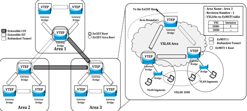
ExMSTP partitions logically the whole network into multiple areas by the preconfiguration as shown in Fig. 3. Each area has an unique identifier and multiple instances. The area consists of the GBs which has the same area configuration such as an area name, a revision number, and a VXLANs-to-ExMSTI table.
The topology to connect each area is constructed according to the extensible CIST (ExCIST) which ensures a loop-free and provides forwarding path across areas. The ExCIST consists of an extensible CST (ExCST), which connects between the ExCIST area roots in each area, and an extensible IST (ExIST), which represents the each area, only receives and sends all frame including BPDU to the ExCST. The ExCIST root for the ExCST is elected among the GBs in the entire network, and the each area has an ExCIST area root for an ExIST.
The Extensible MSTI (ExMSTI) is responsible for ensuring a loop-free topology of each instance in the area and provides forwarding path by constructing a spanning tree per an instance that is mapped to each VXLAN segment or a group of multiple VXLAN segments. The ExMSTIs do not interact with the outside of the area except ExIST (instance 0). Instead, the instance information is added to a BPDU which is carried by ExIST.
3.2.
Gateway Bridge
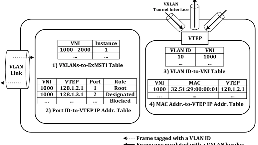
A Gateway Bridge (GB) is an important component for ExMSTP. The GB is a bridge with a VTEP. All frames are sent and received through the GB as a gateway. The frames are encapsulated with a VXLAN header, and are sent to remote hosts in the same VXLAN segment through an UDP/IP tunnel. The GB is the node of spanning tree which is constructed by ExMSTP. The GB has a special role to support interoperability with VLAN based on MSTP. It can become the CIST root bridge of MSTP to interoperate VLAN segments efficiently. The GB manages the following four tables as shown in Fig. 4.
1) VXLANs-to-ExMSTI Table VNI
1000 - 2000 ...
Instance 1 ...
3) VLAN ID-to-VNI Table VLAN ID
10 ...
VNI 1000
...
VNI 1000
…
MAC 32.51:29:00:00:01
...
VTEP 128.1.2.1
... 4) MAC Addr.-to-VTEP IP Addr. Table
VTEP
VLAN Link
2) Port ID-to-VTEP IP Addr. Table VNI
1000 1000 …
VTEP 128.1.2.1 128.1.3.1
...
Port 1 2 ...
Role Root Designated
Blocked
Frame tagged with a VLAN ID
Frame encapsulated with a VXLAN header VXLAN
Tunnel Interface
1) VXLANs-to-ExMSTI table: It manages the mapping information between VNIs and instances, and is used to decide the boundary of an area when the network topology is initiated by ExMSTP.
2) Port ID-to-VTEP IP address table: It manages the mapping information between the corresponding VTEP IP address of neighbor GBs based on a spanning tree and the own port ID which is connected to the neighbor GBs, such as a root port, designated ports, and blocked ports.
3) VLAN ID-to-VNI table: It manages the mapping information between VNIs and VLAN IDs. Each VLAN ID is mapped to only one VNI. Each VXLAN segment is configured by one-to-one mapping.
4) MAC address-to-VTEP IP address table: It manages the mapping information between the MAC address of the host between VTEP IP address which sends and receives frames encapsulated with a VXLAN header. The VTEP looks up this table to determine the destination VTEP IP address for frame which is transmitted to remote hosts.
VXLANs-to-ExMSTI table and VLAN ID-to-VNI table are preconfigured, and Port-to-VTEP IP address entry is added when spanning trees are constructed by ExMSTP. MAC address-to-VTEP IP address entry is added by learning the address information of the received frame.
3.3.
Construction for Spanning Tree
In ExMSTP, Extensible MSTP BPDU (ExMSTP BPDU) is used to construct a spanning tree in VXLAN. Its format is similar to MSTP BPDU and includes GB identifiers, root GB identifier, root path cost, and instance information. The message is classified by defining the new protocol version (0x4) from typical BPDU.
When spanning trees is constructed, GBs periodically exchange ExMSTP BPDU, which is encapsulated with a VXLAN header, between neighbor GBs through an UDP/IP tunnel at every Hello Time. Each GB searches neighbor GBs that have the same ExMST Configuration ID which consists of area name, revision number, and a digest of VXLANs-to-ExMSTI table. If the ExMST Configuration ID is matching, the GBs are bound to the same ExMST area. After dividing the network into multiple areas, ExCIST is constructed to connect the each area, and MSTIs construct a spanning tree per an instance in each area.
The GB checks a bridge identifier which consists of a priority and MAC address from the received ExMSTP BPDU. The GB compares own priority to the priority, and a GB which has the lowest priority in the network is elected as an ExCIST root. Then, in each area, a GB which has the least cost path to the ExCIST root is elected as the ExCIST area root. The ExCIST area root is the root of the ExIST which represents the area and communicates with outside of the area. In each area, the ExMSTIs construct spanning trees for a group of VXLAN segments using VXLANs-to-ExMSTI table. Each spanning tree per an instance is constructed uniquely, and a GB which has the lowest priority in the instance is elected as an ExMSTI root.
The port roles of each GB are assigned according to the root path cost for ExCIST and ExMSTIs. Each port is interconnected to VTI through VTEP. The root port for each spanning tree exists only one in each GB and guarantees the lowest root path cost. Each GB receives ExMSTP BPDU from a connected GBs and forwards a frame to the root of each spanning tree through the root port. The designated ports are used to send all frames including ExMSTP BPDU to neighbor GBs. The blocked port is designated to prevent a loop. When the port role is assigned, the Port-to-VTEP IP address entry is added to the table.
3.4.
Calculation for Root Path Cost
A spanning tree is constructed according to the shortest path to a root. Therefore, each node in the spanning tree can send a frame to the root through a path which has the lowest cost.
The root path cost is calculated when ExMSTP BPDU are exchanged. After election a root GB for the spanning tree, the root path cost is calculated from the root GB and starts from zero. The path cost per the next node of the spanning tree is accumulated to the root path cost.
3.5.
Frame Forwarding
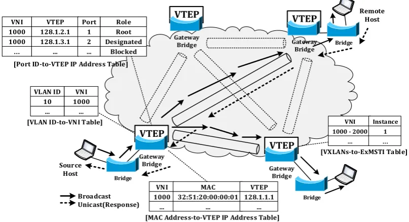
The packet flow in VXLAN based on ExMSTP is shown in Fig. 5. A host starts to communicate with a remote host which is located in the different network by sending an Ethernet frame. When a bridge receives the frame from the host, it inserts a related VLAN tag into the frame. The bridge looks up the corresponding entry in the VLAN configuration table which contains VLAN ID, the destination MAC address, and the output port. If it finds out the entry, the frame is sent out through the output port. If not, the frame is flooded to all ports related with the VLAN ID except the input port according to a spanning tree which was constructed by MSTP.
Bridge
Bridge Bridge
VLAN ID 10
...
VNI 1000
... [VLAN ID-to-VNI Table]
[MAC Address-to-VTEP IP Address Table] VNI
1000 ...
MAC 32:51:20:00:00:01
...
VTEP 128.1.1.1
...
[VXLANs-to-ExMSTI Table]
VNI 1000 - 2000
...
Instance 1
… VTEP
Gateway Bridge
VTEP
Gateway Bridge
VTEP
Gateway Bridge
VTEP
Gateway Bridge
[Port ID-to-VTEP IP Address Table] VNI
1000 1000
…
VTEP 128.1.2.1 128.1.3.1
...
Port 1 2 ...
Role Root Designated
Blocked
Source Host
Remote Host
Broadcast Unicast(Response)
Fig. 5. The packet flow in VXLAN based on ExMSTP.
When the frame with VLAN tag arrives at a GB, the GB which called a source GB (SGB), looks up the VNI related to the VLAN ID by using VLAN ID-to-VNI table and maps the VLAN ID to the VNI. After mapping, the SGB looks up MAC address-to-VTEP IP address entry that includes the destination MAC address and the VTEP IP address of the destination GB (DGB) by using MAC address-to-VTEP IP address table. If there is no matching entry, a broadcast frame is encapsulated with a VXLAN header and is sent out to the remote hosts of the related VXLAN segment through a root port and designated ports which are configured by ExMSTP. Because the ports is mapped to the corresponding VTEP IP address of neighbor GBs which are nodes of a spanning tree by using Port ID-VTEP IP address table, the encapsulated broadcast frame is transmitted to the GBs through an UDP/IP tunnel according to the spanning tree.
which transmits a broadcast frame according to the spanning tree and learns host MAC address in the Layer 2 network.
4.
Comparison Analysis
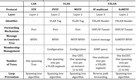
We analyze and summarize main protocols such as STP, PVST, MSTP, IP multicast, and ExMSTP, to construct spanning trees for LAN, VLAN, and VXLAN as shown in Table 1. We focus on the comparison between IP multicast and ExMSTP for VXLAN.
Table 1. The Comparison of Main Protocols to Construct Spanning Tree
LAN VLAN VXLAN
Protocol STP PVST MSTP IP multicast ExMSTP
Layer Layer 2 Layer 2 Layer 2 Layer 3 Layer 2
Identifier - VLAN Tag VLAN Tag VXLAN Header VXLAN Header
Forwarding
Mechanism Port Port Port UDP/IP Tunnel UDP/IP Tunnel Message
to Construct Tree
BPDU BPDU MSTP BPDU Control message ExMSTP BPDU
Membership
Management - Configuration Configuration IGMP query Configuration
Number of Trees
One spanning Tree
One spanning tree per a VLAN segment
One CIST, One spanning
tree per an instance
(1 to 64)
One multicast tree per a VXLAN segment
One ExCIST, One spanning
tree per an instance
(1 to 64)
Loop Prevention
Spanning tree algorithm
Spanning tree algorithm
Spanning tree algorithm
Reverse path forwarding
Spanning tree algorithm
IP multicast is performed based on a Layer 3 network because the membership and multicast tree are managed by a router. In ExMSTP, bridges based on Layer 2 are used to manage the membership and to construct a spanning tree. However, ExMSTP maintains the VXLAN concept that all frames are encapsulated with a VXLAN header and are transmitted through an UDP/IP tunnel to extend a Layer 2 network over Layer 3.
IP multicast uses control message to maintain multicast trees and IGMP query to manage membership, and ExMSTP uses a single ExMSTP BPDU which carries each instance information and the membership is preconfigured. IP multicast constructs a single multicast tree per a VXLAN segment. ExMSTP constructs a spanning tree per an instance which is mapped to a group of multiple VXLAN segments. Thus, ExMSTP can reduce the number of spanning trees compared to IP multicast.
Consequently, ExMSTP provides following contributions. First, ExMSTP can remove IP multicast dependency. IP multicast is used to manage the membership, and to construct a multicast tree to broadcast a frame in VXLAN. It causes that VXLAN depends on IP multicast. If a device does not support IP multicast, VXLAN cannot be operated in the network. In contrast, ExMSTP supports to operate VXLAN by extending MSTP without IP multicast. Second, ExMSTP can obviously reduce the number of spanning trees compared to IP multicast because ExMSTP constructs a spanning tree per an instance which is mapped to each VXLAN or a group of multiple VXLAN segments. ExMSTP provides a simpler topology than IP multicast.
GBs, and MST for VLAN. The GB can become the CIST root bridge of MST. Since the GB participates in both spanning trees as a member node, the proposed scheme can provides more natural interoperability between VXLAN and VLAN.
5.
Conclusions
In this paper, we proposed ExMSTP to construct spanning trees for VXLAN. In typical VXLAN, IP multicast provides multicast trees to broadcast a frame to members in the same VXLAN segment and to ensure a loop-free topology. Thus, VXLAN depends on IP multicast which requires a large amount of network resources to maintain the multicast trees. However, the proposed scheme can replace IP multicast. ExMSTP removes the IP multicast dependency and reduces the number of spanning trees by taking the advantage of MSTP. It also supports interoperability with VLAN by using typical spanning tree algorithm.
Acknowledgment
This research was supported by Korea University.
References
[1] IEEE 802.3. (2002). Carrier sense multiple access with collision detection (CSMA/CD) access method and physical layer specifications.
[2] IEEE 802.1D. (1998). Media Access Control (MAC) Bridges. [3] IEEE 802.1Q. (1998). Virtual Bridged Local Area Networks.
[4] Cisco Systems. (2008). Configuring Rapid PVST+. From http://www.cisco.com
[5] IEEE 802.1s. (2002). Virtual Bridged Local Area Networks, Amendment 3: Multiple Spanning Tree. [6] Mahalingam, M., Dutt, D., & Wright, C. (August 2014). VXLAN: A framework for overlaying virtualized
layer 2 networks over layer 3 networks. IETF RFC 7348.
[7] Ballardie, A. (September 1997). Core based trees (CBT version 2) multicast routing: Protocol specification. IETF RFC 2189.
[8] Fenner, B., Handley, M., Holbrook, H. & Kouvelas, I. (August 2006). Protocol independent multicast — Sparse mode (PIM-SM): Protocol specification (revised). IETF RFC 4601.
[9] Nakagawa, Y., Hyoudou, K., & Shimizu, T. (2012). A management method of IP multicast in overlay networks using OpenFlow. Proceedings of the First Workshop on Hot Topics in Software Defined Networks (pp. 91-96).
[10]Dell. (2014). Comparison between PVST+ and MSTP. A Dell Technical White Paper.
[11]Cisco Systems. (2007). Understanding multiple spanning tree protocol (802.1s). CISCO White Paper. From http://www.cisco.com
[12]Fenner, W. (November 1997). Internet group management protocol, version 2. IETF RFC 2236.
[13]Cain, B., Deering, S., Kouvelas, I., & Fennerr, B. (October 2002). Internet group management protocol, version 3. IETF RFC 3376.
Seong Mun Kim received the B.S., M.S degrees in computer science from Dankook University and Computer Science and Engineering from Korea University, Seoul, Korea in 2007 and 2012, respectively. His interests in research include distributed mobility management, mobility protocol design, software defined networking and performance analysis.