Research of Security Protocol and Data Compression
Method for In-vehicle FlexRay Network
Yi-Nan Xu
*, Meng-Zhuo Liu, Shi-Nan Wang, Yu-Jing Wu, Yi-Hu Xu
Division of Electronic and Communication Engineering, College of Engineering, Yanbian University, Yanji 133002, China.
* Corresponding author. Tel.: +86-433-273-3955; email: [email protected] Manuscript submitted July 2, 2019; accepted September 25, 2019.
doi: 10.17706/ijcce.2020.9.1.18-32
Abstract: With combination between the control systems of vehicle and Internet technology, the in-vehicle network itself is no longer a local area network with security, but faced with great threat from external world. Pay attention to FlexRay, a security protocol composed with data encryption, data authentication and key distribution are produced. Besides, a data compression method was proposed to reduce the real time problem caused by added security designs. Invoking the CANoe software and Freescale S12XF MCU, a simulated in-vehicle bus system was established to evaluate the designs, which showed a robust ability to defense normal attacks and the real time influence was decrease by 7.54% and 6.23% in transmit side and receive side respectively.
Key words: Network security, data compression, FlexRay, electronic control unit.
1.
Introduction
With the improvement of the automobile electronization, it results in the rapid increase of module’s numbers and more complicated systematic functions for realization more advanced software and electronic functions. For general examples, systems like the airbag, the self-adaptive cruise control, and the traction control are implemented on distributed electrical and electronic architecture to obtain more comfortable and safer vehicle environments.
For a long time, to keep in-vehicle network security, all of the OEMs use LIN, CAN or FlexRay separately for internal vehicle communication. But with the development of electronization, it is no longer dependent and secure for in-vehicle network in which various way can access and causing problems of safety for driving, self-privacy and public security.
Recent year, many country has begun to set research programs for vehicular network. Government of USA established a platform to share information and seek corporation that associated with vehicular network [1]. SAE published standard for vehicular network giving a throughout suggestions for constructing a vehicle [2]. The EVITA project trying to build secure vehicular network environment give a three level model to keep the information privacy [3]. OVERSEE is building a vehicle intelligence platform to provide secure applications and access control [4]. In Japan, IPA publishes a brochure in 2013, which produce several solutions for security problems [5].
in-vehicle bus network [6], [7]. Most of nowadays researches are focus on security protocol to keep transmitted data integrity, confidentiality. In [8], [9], a throughout security protocol was proposed and evaluated it by carry out attacks. In [10], a source authentication method was produced but cost too much memory size for in-vehicle ECU. In [11], [12], a lightweight authentication method for CAN is achieved by divide the mission into two separate online calculation and offline calculation. But with more powerful computer, there still a chance to crack it.
For FlexRay, few researches are focus on it. In [13], key exchange method in the security protocol is not efficient with several times of handshakes. In [14], multi-level key chain is used for authentication.
All in all, most of the researches are focus on CAN network, few of them are pay attention to FlexRay, which do not consider real time problem mostly. Although reasonable network scheduling can make data frames transmit more efficiently [15], [16], the real-time problem caused by insufficient computing power of ECU could not be completely solved by network scheduling technology after adopting network security technology. Considering these two requirements, a FlexRay security communication protocol and a data compression method to improve the security performance of FlexRay network are proposed.
The structure of this paper is as follows. Chapter 2 briefly introduces the FlexRay network security threats; Chapter 3 gives the design of the secure communication protocol, and describes it in detail in the form of flow chart and pseudo-code; Chapter 4 describes the concrete steps of data compression method; Chapter 5 verifies the proposed secure communication protocol and data compression method by experiments; and finally, Chapter 6 summarizes and prospects the full text.
2.
Security Threat to FlexRay
Due to the diversification of drivers' demand for automobile functions, various electronic products are added to the automobile, which improves the automobile driving assistance function but brings a threat to the network security of the in-vehicle bus system.
The development of in-vehicle bus system for last half a century, LIN, CAN, FlexRay and other in-vehicle bus protocols have not considered network security issues. When the automobile electronic control system is connected to the smartphone, OBD II scanner and wireless network system, it is easy to reveal the privacy information of the in-vehicle network and the possibility of the losing the control of the automobile caused by hacker is extremely high. Therefore, for FlexRay, we can summarize the following two network security problems: first, the lack of message authentication mechanism. Every electronic control unit of a car fully believes in the origin of the data it receives. An attacker can forge a data frame with a legitimate frame ID, and the receiving node will receive it indiscriminately and change the car's behavior according to the content of the data frame. Secondly, because FlexRay broadcast feature, all nodes connected to the bus can read real-time communication data, including third-party malicious electronic products or malicious bus monitoring program.
Therefore, how to defend the vulnerabilities in the data layer and physical layer of the communication protocol is the core problem to be solved in the development of automobile.
3.
Proposed Security Protocol
In view of the security defects of FlexRay, a security protocol was proposed. It mainly includes three parts: data encryption, message authentication and key distribution.
Data Encryption and Authentication Algorithm
3.1.
diffusion, confusion and non-linear functions. In addition, the counter (CTR) mode is used to encrypt the original data, so when the length of the data is not an integer multiple of the AES packet, the original data does not need to be filled, and the encrypted result is the same as the original data length.
In the aspect of message authentication, message authentication code is calculated by HMAC algorithm with SHA-1 as its core, using the same key in data encryption, and attaching the message authentication code after the sending data.
Key Distribution Method
3.2.
In communication, the distribution of session keys has always been a difficult problem. Generally, handshakes are needed at both ends of the communication system, which is too slow for the in-vehicle network, and the real-time performance is not guaranteed. The method proposed in this paper uses one-way key chain and publishes the key in plaintext after a certain delay. The process is as follows:
Before the communication starts, each sending node needs to calculate a fixed-length key chain through a one-way function, where the one-way function can be various hash functions. In the calculation process, the hash function needs to be called recursively.
At the same time, the two sides need to negotiate the following two parameters in advance:
(1) Tint
: Length of time slot. Communication time is divided into many equal-sized lengths, each of which
is Tint
.
(2) d: Publishing interval. The size of d is an integral multiple ofTint, and every d passes, a used key will be published.
Because the object of this paper is the FlexRay communication network, which uses the TMDA mode to communicate, thus the time has been divided into equal-sized time slots by the protocol. Therefore, the parameterTint can be set to one or more communication cycles.
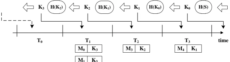
The key generation and distribution method in communication is shown in Fig. 1. In the figure,T1 is a time slot with the length ofTint. TakeT1as an example, in the current period of time, all the security operations involved in sending data are completed by K2, and after each sending data, the key K3 used in the
previous time slot is published in plaintext. From the time slotT1when the key K2 is used to the time slot
T2when the key is published, the interval between it is d. In Fig. 1, d is set to be equal toTint, that is, the key is published every time slot. Since the key chain is generated by a one-way hash function and is used in the reverse direction, it is impossible to deduce the next encryption key to be used from the newly published key and only wait for the publication of the sender.
When receives the message containing the key, the receiver can use the received key as input for hashing operation. Because the use of the key chain is contrary to the direction of generation, if the key is correct, the result of the hash operation should be the key of the previous cycle.
Fig. 1. Key distribution process.
K0 K1
K2 H(K1) H(K0) H(S)
H(K2)
K3
time
T0 T1 T2 T3
M3 K2 M4 K1
Security Protocol
3.3.
The security protocol proposed in this paper combines data encryption, message authentication and key distribution strategy. It designs specific operation steps for four processes: sender initialization, receiver initialization, sending and receiving.
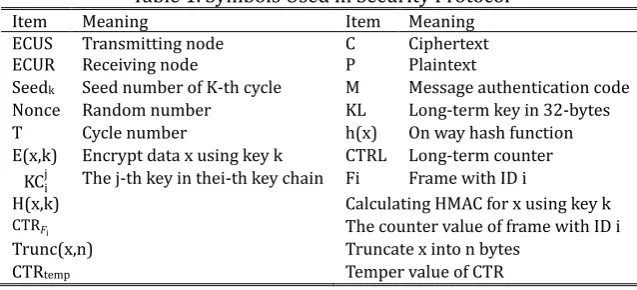
For convenience, some symbols are used in describing security protocol, and their definitions are shown in Table 1.
Table 1. Symbols Used in Security Protocol
Item Meaning Item Meaning
ECUS Transmitting node C Ciphertext
ECUR Receiving node P Plaintext
Seedk Seed number of K-th cycle M Message authentication code
Nonce Random number KL Long-term key in 32-bytes
T Cycle number h(x) On way hash function
E(x,k) Encrypt data x using key k CTRL Long-term counter KCij The j-th key in thei-th key chain Fi Frame with ID i
H(x,k) Calculating HMAC for x using key k
CTRFi The counter value of frame with ID i
Trunc(x,n) Truncate x into n bytes
CTRtemp Temper value of CTR
In the whole protocol, the length of the key chain can be set appropriately, but need to ensure that it can be updated online in a timely manner, in this study we set the length in 10. In addition, all counter lengths need to be the same as the block lengths of the encryption algorithm, which is 16 bytes. All message authentication codes are truncated to 10 bytes. At the same time, in order to verify the key and the initial counter value, a long-term key KL and a long-term counter CTRL are set up in all ECUs, and the two
parameters are consistent in all ECUs within the same node cluster.
In order to explain the specific design of security protocol more clearly, the flow chart of functional modules and pseudo-code of specific operation steps are given respectively for the four processes, and explain the design purpose and meaning of specific operation steps through text description.
During the initialization process of the sender, its modularization process is shown in Fig. 2. Pseudo-code descriptions of each step is as follows:
Step 1:Generate Seed1 Step 7:for Fx = { Fi,Fj,Fk,…, Fn}
Nonce = hSHA-1(Seed1Fx)
CTRFx = Trunc(Nonce,8)||{0}64
CCTRL = EAES-256(CTRL,KL)
CCTRFx = CCTRL CTRFx
CTRL = CTRL + 1
end loop Step 2:for j = 1:10
if(j == 1)
KC11 = hSHA-1(Seed1)
endif
KC1j = hSHA-1(KC1j-1)
end loop Step 3:MKC
1 10 =
HSHA-1(KC110||CTRL,KL)
Step 8:MCTRF=
HSHA-1(CCTRFi||…||CCTRFn||CTRtemp, KL)
Step 4:CTRtemp = CTRL
Step 5:CTRL = CTRL + 1 Step 9:Send
{CCTRF
i||…||CCTRFn||MCTRF||MKC110} to receiver
Step 6:GenerateSeed1Fi,Seed
1 Fj
Fig. 2. Initialization process of the sender.
At the sending node, two types of seed values Seed1 andSeed1Fi, ... ,Seed1Fn
, are generated.Seed
1 is used tocalculate the key chain, and others are used to generate the initial counter value of each data frame. In the first cycle after the start of communication, all receiving nodes are not aware of any information of the key chain, so it is necessary to send the message authentication code of the first used key to all nodes. At the same time, in order to ensure the real-time, it is necessary to calculate the message authentication code in combination with the long-term counter value. The same operations are performed on the initial counter values of each data frame, except that they need to be encrypted once more and the cipher text also needs to be sent to the receiver.
The initialization process of the receiver is relatively simple. After receiving the cipher text of all the counter values of the data frames, the HMAC algorithm is used to authenticate them. If passed, the long-term counter CTRL and the long-term key KL are used to decrypt them in AES-CTR mode, and then the
counters are separated in 16 bytes. After each initialization of the key chain, the message authentication code of the key is sent to each receiver before the key chain is formally used. The receiver will save the message authentication code temporarily until the first key used in the new key chain is broadcast, and then authenticate it.
The flow chart of the Transmitting process is shown in Fig. 3. The specific steps can be expressed as follows:
Step 1: CCTRFx = EAES-128(CTRFx,KCi
j)
Step 2: CPT= CCTR
𝐹𝑥 PT
Step 3: MPT = HSHA-1(CPT||CTRFx,KCi
j) Step 4: CTRFx = CTRFx + 1
Step 5: Send CPT||KCij-1||MPT
Fig. 3. Transmission process.
Whenever there is data ready for transmission, the key in KC is used to encryptCTRFxwith AES-128 algorithm. The result is XOR with plaintext then cipher text is obtained. Next, the message authentication code is computed using the same key after concatenating the cipher text withCTRFx. Finally, the cipher text
Start Generate initial key chain
Calculate MAC of initial session key
Generate initial CTR for frames Calculate MAC
and ciphertext of frames Send MAC and
ciphertext of CTR, MAC of initial
session key End
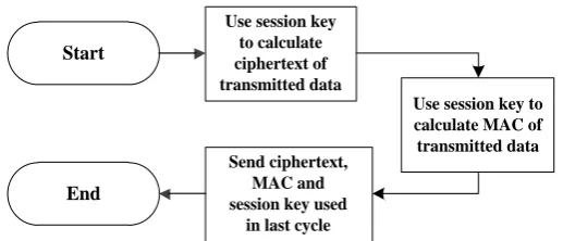
Start
Use session key to calculate ciphertext of transmitted data
Use session key to calculate MAC of transmitted data Send ciphertext,
MAC and session key used
is concatenated with the key used in the previous cycle and the message authentication code. At the same time, CTRFxshould be added by one to itself.
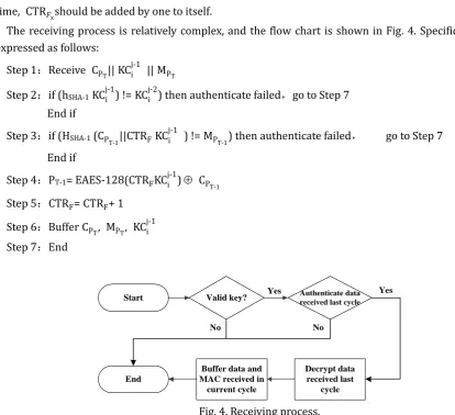
The receiving process is relatively complex, and the flow chart is shown in Fig. 4. Specific steps can be expressed as follows:
Step 1:Receive CPT||KCij-1 ||MPT
Step 2:if (hSHA-1KCij-1) !=KCij-2) then authenticate failed,go to Step 7
End if
Step 3:if (HSHA-1 (CPT-1||CTRFKCi j-1
) !=MPT-1) then authenticate failed, go to Step 7 End if
Step 4:PT-1= EAES-128(CTRFKCij-1) CP
T-1
Step 5:CTRF=CTRF+ 1
Step 6:BufferCPT, MPT, KCij-1 Step 7:End
Fig. 4. Receiving process.
Before explanations of pseudo code of the receiving process, it is necessary to declare that the verification of the received data by the receiver needs to be delayed by one cycle. Because the sender will publish the key calculating the message authentication code of the corresponding data frame in the next cycle, thus all the data received in the current cycle will be stored unconditionally, and then authenticated and decrypted after the key is received in the next cycle.
It should be noted that since no key needs to be published in the first cycle of communication, this part of the key field placed in the payload is set to "0". And in this cycle, no data can be verified and decrypted, the received data will be temporarily buffer, no other operations will be done, and the value of the data frame counterCTRFx will not increased. It is worth noting thatCTRFx increases only when the data frame is authenticated.
4.
Data Compression Method
Design of Data Compression Method
4.1.
On the in-vehicle bus network, ECUs with different functions are carried, and these ECUs complete their tasks according to the program. Tasks such as data encryption and message authentication code calculation take a long time for the CPU to complete an operation, and with the increase of the amount of communication data, the occupied time increases linearly, which may cause the normal functions of ECU to be unable to complete in time. Previous research on data compression methods of in-vehicle network
Start
Decrypt data received last
cycle Valid key?
End
No
Authenticate data received last cycle
No
Yes
Buffer data and MAC received in
mainly focuses on CAN bus and has different compression purposes [17], [18]. In view of the specific situation of this study, a compression method for FlexRay data is proposed to reduce the amount of communication data, at the same time achieve data security purposes. This shortens the time that the safety-related calculations occupy the main processor, so that the normal functions of the ECU can be completed on time.
The basic idea of the data compression method proposed in this paper is to send only the change of data, but not the complete value of data. Because the data of in-vehicle communication are mostly control signals or some continuously changing signals, and the communication cycle length of the protocol is at the level of milliseconds. Therefore, the change of the same signal in the two adjacent periods may be extremely small or no change at all. The following describes the specific operation of the compression method:
The whole process of compression is shown in Fig. 5, where SignalL1, SignalC1 and SignalD1 represent the
complete value of last cycle, the complete value of current cycle and the change of signal value, respectively. When a communication cycle arrived at the transmitter side and the data of a signal is ready to be sent, the complete value of the current period of the signal is XOR with the complete value of the previous period. The non-zero bytes in the result, i.e. the changed bytes, are extracted and sent to the receiver as compressed data. At the receiving end, the corresponding inverse operation can be carried out to obtain the complete data of current cycle. But the specific operation of this process needs some auxiliary information to complete. The auxiliary information here is the indicator of compressed data.
Fig. 5. Data compression on transmitting and receiving side.
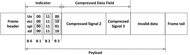
For the data frame shown in Fig. 6, an indicator bit field is set for each compressed signal. The length of the field matches the length of the signal, that is, each byte in the signal has a bit corresponding to the indicator bit field of the signal. When a byte in a signal is changed, an extraction of this byte will happen and the indicator bit of the corresponding byte is set to "1", besides the indicator bit of the unchanged byte is set to "0". The extracted bytes are repositioned in the payload in a left-aligned manner with the indicator bits. The receiver can therefore find the changed bytes according to the indication bit to carry out de-compression.
Fig. 6. Compressed data format. SignalL 1
SignalC 1Transmitter
SignalD 1
SignalL 1
SignalD 1 Receiver SignalC 1 SignalD 1 FlexRay bus Un occ upi ed Un occ upi ed Payload 00 00 00 00 00 00 00 00 Frame header Frameheader Compressed Signal 2Compressed Signal 2 Frame tailFrame tail
Compressed Signal 3 Compressed
Signal 3
Indicator Compressed Data Field
Invalid data Invalid data
In addition, it should be noted that the purpose of the compression method proposed in this paper is not to reduce the amount of data sent, but to reduce the amount of data that encryption algorithm and message authentication algorithm need to progress, so as to shorten the time occupied in the CPU by the operation of security protocol.
Combination of Security Protocol and Data Compression Method
4.2.
The data compression method proposed in this paper is to reduce the CPU time occupied by the security algorithm and reduce the number of times the security algorithm is used. When the data compression algorithm is combined with the security protocol, it can detect whether the number of operations of AES or HMAC algorithm decreases by using the data compression method according to the length of the specific data frame, and if there is no improvement, signals are still sent in the form of original one. In addition, when the compressed data length is zero, the encryption is no longer performed, and the input of message authentication is only the counter value of the corresponding data frame.
5.
Experiment
Experimental Environment
5.1.
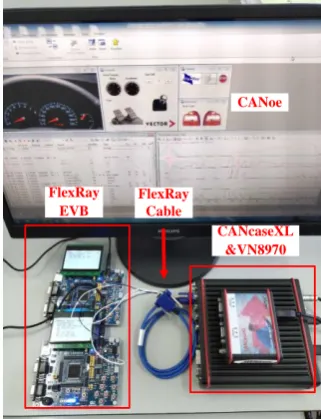
In this paper, the simulation bus environment is built by using the in-vehicle bus simulation tool CANoe of German Vector Company and two FlexRay development boards EVB912XF of Freescale Company, i.e. the real vehicle ECU. The hardware-in-the-loop simulation experiment is completed. The Abstract module diagram of the experimental environment is shown in Fig. 7 and the actual environment is shown in Fig. 8.
Fig. 7. Abstract module of experimental environment. Fig. 8. Actual experimental environment.
Evaluation
5.2.
The experiment is divided into two parts, which verify the proposed security protocol and data compression method. In the process of validating the security protocol, the virtual ECU in CANoe is used as the attack node to send malicious messages to the evaluation board EVB9S12XF. The validity of the design is verified by analyzing the communication data on the bus after joining the secure communication protocol. In the process of validating the data compression method, the effectiveness of design is validated by comparing the amount of data that needed to be processed by the security algorithm before and after using the data compression method.
EVB 9S12XF512
EVB 9S12XF512
BP
BM
BP
BM
2 7
VN8970 Interface FRcable
USB CANoe
v9.0 PC
CANoe
FlexRay EVB
CANcaseXL &VN8970 FlexRay
5.2.1.
Validation of security protocol
Firstly, a virtual ECU is built in CANoe. The result is shown in Fig. 9. Among them, ECU_1 and ECU_2 represent FlexRay evaluation board, and ECU_3 is a virtual ECU which one as attack node.
Fig. 9. Simulated bus environment in CANoe.
In order to show the results more clearly, only static frame F4 with frame ID 4 and dynamic frame F63 with
frame ID 63 are selected as representatives to verify the design. Among them, the length of F4 is 20 bytes,
and the update period is 1; the length of F63 is 8 bytes, and the update period is 8. The security protocol is
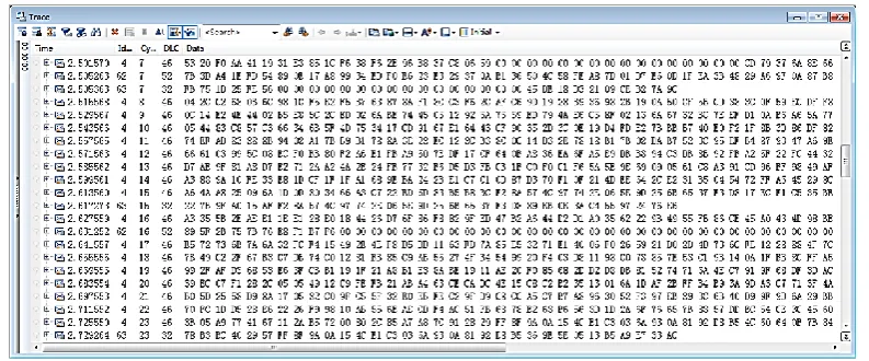
coded in C language in Codewarrior environment and downloaded to the evaluation board. At both sides of the transceiver and receiver, data encryption, authentication and key chain calculation are accomplished by the combination of S12X processor and XGATE coprocessor. The use of XGATE coprocessor greatly improves the computational efficiency of the security algorithm and guarantees the real-time performance. After the application of secure communication protocol, the data transmitted on the bus is shown in Fig. 10.
Fig. 10. Secure data transmitted on bus.
In the first communication cycle, three data frames with IDs of 4, 62 and 63 were sent. The ID of the application data frame is 4 and 63, and the frame with ID 62 is used to send the cipher text, message authentication code and initial key of the initial IV. The first 32 bytes of F62 are the cipher text of
CTRF4||CTRF63and its calculation method is shown in Step 7 in the initial process of the sender in Chapter 3. The message authentication code of TRF4||CTRF63 is from 33 bytes to 42 bytes, which is shown in Step 8 in
calculation method is as shown in the transmission process Step 1~2; the next 16 bytes are the used key of the previous cycle. Since the seventh cycle is the first cycle of formal communication no key need to be published; the last 10 bytes are message authentication code, calculation method is as shown in Step 3 of transmission process.
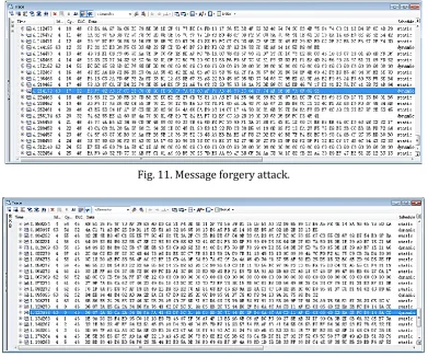
Next, virtual ECU is used to attack real ECU equipped with security protocol. Firstly, F63 is used to carry
message forgery attack, as shown in Fig. 11. At time point 4.214178, forged data frames appear on the bus, just within the normal transmission time interval of 4.144185 and 4.256174. After receiving the forged data, the node first extracts the key carried by the frame and hashes the key. If the result is equal to the key received in the previous cycle, the first step verification is passed, then the cipher text and message authentication code in payload are temporarily stored. However, the data frame is forged, and the key carried by the attacking node is incorrect because the attacking node does not possess the key and CTR and other functional parameters. Compared with F4 sent in 17 cycles, the key carried by F4 in 16 cycles can be
obtained by one hash operation. On the contrary, F63 in 17 cycles carries different key from that of F4 in the
same period, so it is almost impossible to get the key published in the previous cycle through hash operation.
Fig. 11. Message forgery attack.
Fig. 12. Message replay attack.
Continue to carry message replay attack with F63, as shown in Fig. 12. Because FlexRay is a TDMA
communication protocol, it is impossible to retransmit a data frame with the same frame ID. However, considering that the key carried by different periodic data frames are varied, the way of delayed periodic replay attack cannot pass the first step verification, such as the message forgery attack. Therefore, in this attack, we changed the object of the retransmit, and it is decided not to retransmit F63 but to retransmit F4,
and 1.095986. The time points of replay data frames are 1.012009 and 1.123998. It can be seen that the payload of replay data frames is exactly the same as that of F4 in the same cycle. For the receiving node, it
will temporarily save the replay data frames until the next cycle to verify. However, because the counter CTRF maintained by different data frames is not same, and the input of the message authentication code is
CP
T-1||CTRF, then it cannot generate a valid message authentication code. Therefore, the message replay
attack also fails and cannot work under the protection of security protocol.
5.2.2.
Validation of data compression method
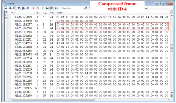
In order to improve the efficiency of FlexRay communication and achieve the goal of double encryption, this study has carried out data compression on bus data. The transmission of raw data and compressed data is shown in Fig.13 and 14,respectively. The original data length of F4 is 20 bytes, which contains 5 signals. Each signal’s length is 4 bytes. The indicator needs 20 bits, at least 3 bytes. But because the FlexRay protocol stipulates that the payload length must be even number, thus the indicator actually occupies 4 bytes.
Fig. 13. Raw data transmitted on bus.
Fig. 14. Compressed data transmitted on bus.
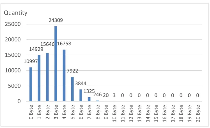
In order to show the improvement of the time occupied by the security algorithm in CPU after data compression, in this paper we uses the communication data extracted from the real car to verify. In 96 000 communication cycles, the number of F4 and F63 extracted was 96 000 and 12 000 respectively. The length
of F4 is 20 bytes before compression and F63 is 6 bytes before compression. After compression, the data
length distribution of F63 and F4 is shown in Fig.15 and 16.
Fig. 15.Compressed data length distribution of F63.
Fig. 16. Compressed data length distribution of F4.
For a data frame, the total time needed for each security operation can be calculated by formula (1):
(1)
where DFi is the total time needed for Fi security operation, DEn is the time required for encryption, TEn
is the number of times required for encryption, D𝐻𝑀𝐴𝐶 is the time required for message authentication, and D𝑠ℎ𝑎1 is the time required for a SHA-1 hash operation for key verification at the receiving end. Then, for F4 and F63, according to the measured result of each security algorithm in hardware, the total time
required for their security operation is shown in Table 2.
Table 2. Time Needed for Security Operations
Transmitter(unit:ms) receiver(unit:ms)
F4 F63 F4 F63
4.904 4.572 5.936 5.604
According to formula (1), the calculation method of the average occupancy time of processor for security operation can be deduced, as shown in formula (2).
(2)
11821
169 7 0 0 2 0
-3000 2000 7000 12000
0 Byte 1 Byte 2 Byte 3 Byte 4 Byte 5 Byte 6 Byte
Quantity
10997 14929 15646
24309
16758
7922
3844 1325
246 20 3 0 0 0 0 0 0 0 0 0 0 0 5000 10000 15000 20000 25000 0 By te 1 By te 2 By te 3 By te 4 By te 5 By te 6 By te 7 By te 8 By te 9 By te 10 By te 11 By te 12 By te 13 By te 14 By te 15 By te 16 By te 17 By te 18 By te 19 By te 20 By te Quantity 1 i
F En En HAMC sha
D
D
T
D
D
i
i
i i 1 i
(
)
(
)[
(
)]
total total total avrg En HMAC sha FF
D
F
D
F
D
F
D
N
Which D𝐹 i
avrg
is the average time processor be occupied, NFi is the number of Fi, DtotalEn
,
DHMACtotal and Dsha1totalis the time needed for the operation of encryption, message authentication and key authentication to all data frames. Then, before and after compression, comparison of the time needed for CPU to carry out the security operation is shown in Table 3. Because the length of F4 and F63 are not more than 64 bytes, and the
HMAC calculation is still needed even if the length of compressed data is zero, the time needed for message authentication has not been improved.
From Table 3, it can be concluded that the time taken by all sending data encryption of F4 is shortened by
35353ms after compression, with a change rate of 55.4%; the time taken by all sending data encryption of F63 is shortened by 3927ms after compression, with a change rate of 98.5%; the average time taken by all
security operations of F4 is shortened by 0.37ms at both sending and receiving sides, with a change rate of
7.54% and 6.23%; the average time taken by all security operations of F63 is shortened by 0.328ms at both
sending and receiving sides, with a change rate of 7.17% and 5.85%.
Table 3. Time Needed for Security Operations before and after Compression
Channels Before Compression After Compression
Frame F4 F63 F4 F63
Bytes need to Encrypt 1920000 72000 260307 193
Bytes need to Authenticate 1920000 72000 19200000 72000
(ms) 63744 3984 28391 56.772
(ms)
Transmitter 4.904 4.572 4.534 4.244
Receiver 5.936 5.604 5.566 5.276
6.
Conclusions
In this paper, in order to deal with the security problem of in-vehicle bus network, a network arrangement scheme combining data encryption, message authentication and key distribution for FlexRay bus is proposed, and a data compression method is proposed for the real-time problem of vehicle communication. And an auxiliary data compression method is proposed for the real-time problem of in-vehicle communication. By validating the design with hardware-in-the-loop simulation, it can be proved that the proposed secure communication protocol has the function of resisting the network attack behavior, and the data compression method improves the efficiency of FlexRay communication while achieving the effect of double encryption at the same time.
Conflict of Interest
The authors declare no conflict of interest.
Author Contributions
Yinan Xu: Conceptualization and supervision; Mengzhuo Liu and Shinan Wang: Methodology and writing of original draft; Yujing Wu: Software and formal analysis; Yihu Xu: Validation and review & editing of original draft.
Acknowledgment
This research was supported by National Natural Science Foundation of China Grant Number 61763047.
References
[1] Hu, Q., & Luo, F. (2018). Review of Secure communication approaches for in-vehicle network.
total En
D
i avrg F
International Journal of Automotive Technology, 19(5), 879–894.
[2] Vehicle Cybersecurity Systems Engineering Committee. (2016). Cybersecurity guidebook for cyber-physical vehicle systems. SAE International.
[3] Weyl, B., Henniger, O., Ruddle, A., Seudié, H., Wolf, M., & Wollinger, T. (2009). Securing vehicular on-board IT systems: The EVITA project. Proceedings of the 25th Joint VDI/VW Automotive Security Conference (pp. 1-14). Ingolstadt, Germany.
[4] Groll, A., Holle, J., Ruland, C., Wolf, M., Wollinger, T., & Zweers, F. (2009). Oversee a secure and open communication and runtime platform for innovative automotive applications. Proceedings of the 7th Embedded Security in Cars Conference (pp. 1-10). Germany.
[5] Information-Technology Promotion Agency. (2013). Approaches for vehicle information security. IPA Report.
[6] Miller, C., & Valasek, C. (2013). Adventures in automotive networks and control units. Proceedings of the DEF CON 21 (pp. 15-20). USA.
[7] Miller, C., & Valasek, C. (2015). Remote exploitation of an unaltered passenger vehicle. Proceedings of the Black Hat 13 (pp. 84-86). USA.
[8] Woo, S., Jo, H. J., & Lee, D. H. (2015). A practical wireless attack on the connected car and security protocol for in-vehicle CAN. IEEE Transactions on Intelligent Transportation Systems, 16(2), 993-1006. [9] Woo, S., Jo, H. J., Kim, I. S., & Lee, D. H. (2016). A practical security architecture for in-vehicle CAN-FD.
IEEE Transactions on Intelligent Transportation Systems, 17(8), 2248-2261.
[10]Kang, K. D., Baek, Y., Lee, S., & Son, S. H. (2017). An attack-resilient source authentication protocol in controller area network. Proceedings of the 2017 ACM/IEEE Symposium on Architectures for Networking and Communications Systems (ANCS) (pp. 109-118). Beijing, China.
[11]Wang, Q., & Sawhney, S. (2014). VeCure: A practical security framework to protect the CAN bus of vehicles. Proceedings of the 2014 International Conference on the Internet of Things (IOT) (pp. 13-18). USA.
[12]Groza, B., & Murvay, S. (2013). Efficient protocols for secure broadcast in controller area networks.
IEEE Transactions on Industrial Informatics, 9(4), 2034-2042.
[13]Mousa, A. R., NourElDeen, P., Azer, M., & Allam, M. (2016). Lightweight authentication protocol deployment over FlexRay. Proceedings of the 10th International Conference on Informatics and Systems - INFOS ’16 (pp. 233-239). Egypt.
[14]Gu, Z., Han, G., Zeng, H., & Zhao, Q. (2016). Security-aware mapping and scheduling with hardware co-processors for FlexRay-based distributed embedded systems. IEEE Transactions on Parallel and Distributed Systems, 27(10), 3044-3057
[15]Jin, S., Liu, M., Wu, Y., Xu, Y., Zhang, J., & Xu, Y. (2018, Oct.). Research of message scheduling for in-vehicle FlexRay network static segment based on Next Fit Decreasing (NFD) algorithm. Applied Science, 8(11), 2017.
[16]Lee, T.-Y., Lin, I.-A., Wang, J.-J., & Tsai, J.-T. (2018, Nov.). A reliability scheduling algorithm for the static segment of FlexRay on vehicle networks. Sensors, 18(11), 3783.
[17]Kelkar, S., & Kamal, R. (2014). Boundary of fifteen compression algorithm for controller area network based automotive applications. Proceedings of the 2014 International Conference on Circuits, Systems, Communication and Information Technology Applications (pp. 162-167). India.
Copyright © 2020 by the authors. This is an open access article distributed under the Creative Commons Attribution License which permits unrestricted use, distribution, and reproduction in any medium, provided the original work is properly cited (CC BY 4.0).
Yi-Nan Xu was born in Jilin Province of China. He received the Ph.D. degree in electronics engineering from the Chonbuk National University, Korea, in 2009.
He is a professor of the Division of Electronics and Communication Engineering of Yanbian University, Yanji, China. His research interests include the in-vehicle network and automobile electronic control.
Meng-Zhuo Liu was born in Jilin Province of China. He received the bachelor degree in communication engineering from YanBian University, China, in 2017.
He is a currently working toward a master degree in the area of in-vehicle network, which include the design of security architecture of FlexRay.
Shi-Nan Wang was born in Jilin Province of China. She received the bachelor degree in communication engineering from Yanbian University, China, in 2019.
She is a currently working toward a master degree in the area of in-vehicle network, which include the design of security architecture of FlexRay.
Yu-Jing Wu was born in Jilin Province of China. She received her M.S. and Ph.D in electronic and information engineering from Chonbuk National University, South Korea, in 2013 and 2016, respectively.
She is a lecturer of the Division of Electronic and Communication Engineering of Yanbian University, China. Her research interests are in the area of VLSI implementation for digital signal processing and communication system, which include the design and in implementation of security protocol for in-vehicle networks.
Yi-Hu Xu was born in Jilin Province of China. He received the Ph.D. degree in electronics engineering from the Chonbuk National University, Korea, in 2014.