www.ijaera.org 63
Voltage Sag Ride-Through for Adjustable
Speed Drives in Industrial Systems
Dr. S. S. Deswal1, Dr. Rajveer Mittal2, L. P. Singh3, Dr. D. K. Jain4 1
Dean (Academics) & Associate Professor, EEE, Maharaja Agrasen Institute of Technology Sector-22, Rohini, Delhi, INDIA, E-mail: [email protected]
2
Head & Associate Professor, EEE, Maharaja Agrasen Institute of Technology Sector-22, Rohini, Delhi, INDIA, E-mail: [email protected]
3
Assistant Professor, EEE, Maharaja Agrasen Institute of Technology Sector-22, Rohini, Delhi, INDIA, E-mail: [email protected]
4
Head & Professor, Dept. of Electrical Engg., DCRUST, Murthal, Haryana, INDIA, E-mail: [email protected]
Abstract: This paper is aimed at providing power/energy to the Adjustable speed drives during
unsymmetrical voltage sag conditions by using supercapacitor as an energy storage system. The energy storage device will inject energy at the time of voltage sag and keep the ASDs in operation and hence avoid stoppage of the process in the processing industries. This method will be economical as compared to the existing methods and can be used as a retrofit in the existing industrial ASDs. Boost converter along with supercapacitor as an energy storage device has been used as the hardware to compensate the DC-link voltage because of its simplicity and cheap price. Based on the proposed topology, simulation model in MATLAB 7.5 (Sim Power Block set) has been developed for voltage unbalance conditions with supercapacitor as an energy storage device. The designed control technique is modelled, simulated and successfully implemented in the laboratory. The extensive simulation results supported by experimental results were provided to validate the proposed system.
Keywords:Voltage sag; Supercapacitor; Adjustable speed drives; Power quality; Ride-through
I. INTRODUCTION
The application of adjustable-speed drives (ASD’s) in commercial and industrial facilities is increasing due to improved efficiency, energy savings, and uninterrupted process control. However, ASD’s are often susceptible to voltage disturbances, such as sags, swells, transients (due to capacitor switching), and momentary interruptions (outages). Electric power quality relates to non-standard voltage, current or frequency deviation that results in failure or misoperation of end-user equipment. According to survey reports, voltage sags of 10%–30% below nominal for 3–30-cycle durations account for the majority of power system disturbances, and are the major cause of industry process disruptions [1-5].
www.ijaera.org 64 that increases the electrical stresses on the DC-Link choke inductor (if used) and the DC-Link electrolytic capacitors, potentially shortening the capacitor lifetime. Third, voltage unbalances can give rise to ripple torque of magnitude double the fundamental frequency in the ASD’s induction machine which increases the mechanical and thermal stresses.[6-7]
II. NATIONAL AND INTERNATIONAL STATUS REVIEW
The review carried out clearly indicates that power shortages in India have had significant negative impacts, in the short term, on the national value added (GDP), and, in the long term, on the growth rate of value added (GDP). At the aggregate level, power consumers in India face power shortages to the tune of 12.6% in peak power (kVA) availability and 7.5% in energy (kWh) availability, it is clear that India’s GDP and GDP growth rate will continue to be adversely affected in future [7-9].
In India no comprehensive technique is followed in this context and merely uneconomical solution like providing full rated uninterrupted power supplies are used. Till date, the use of ASDs is quite less, which is otherwise necessary for energy conservation and efficiency. Once the proportion of ASDs is higher than it will be necessary to study the impact of power quality disturbances on these drives.
As per the International Status Review, it is observed that the modern industrial process equipments such as “Adjustable Speed Drives” are often susceptible to power fluctuations and interruptions. The adverse effect of symmetrical faults and its ride-through capabilities has been reported in the literature. To design Adjustable Speed Drives which may ‘ride-through’ during power supply disturbances is a challenging research work [8-10].
III. EXISTING RIDE-THROUGH TOPOLOGIES
Voltage sag can cause most of its damage to equipment and circuit protection devices when it is cleared. At this point, large voltage and current transients are present, as the system returns to normal. The DC-Link voltage is low (due to the preceding sag), and once full AC voltage is available, the DC-Link capacitor will draw a large recharge current. Pre-charging circuits to reduce initial current when the ASD’s are first switched on are normally timed out. This recharging current may even be sufficient to burn out the diodes in the rectifier if the incoming circuit protection does not trip first.
There are many different types of mitigation techniques available to control or mitigate the effect of voltage sags on ASD’s. They are based on software control, hardware (such as increasing the DC-Link capacitor size), or a combination (such as a boost converter) [11, 12].
The different ride-through topologies require energy storage devices injecting power at the DC-Link during voltage sags as described in the literature are as follows:
Adding capacitors across the DC-Link
Load inertia
Variable-torque loads variable-torque loads
Battery backup
Flywheel and motor-generator (M/G) combination
www.ijaera.org 65
Supercapacitor
IV. MAIN OBJECTIVE AND PROPOSED TOPOLOGY
The objective of this section is to investigate the performance of an ASD’s under three-phase unsymmetrical fault leading to balanced and unbalanced voltage sag at PCC. The proposed topology is designed by using supercapacitor as energy storage device along with boost converter across DC-Link as a ride-through alternative for ASD’s.
The performance of ASD’s under unsymmetrical fault conditions has been simulated using MATLAB Simulink Power System Block set tool box. The functional block diagram is shown in Figure 1. A three-phase programmable voltage source feeds the power bus to PCC through series impedance (taken as resistance of 0.1 ohm assuming the length of line to be very small). Two independent feeders are connected at this PCC bus; one feeds the ASD’s and the other is connected to the load. The faults are created at the load feeder to study the impact of voltage sags on the ASD’s connected at the same PCC. The shunt impedance method has been used to generate voltage sags. At the time of faults the fault current flows through the impedance leading to a voltage drop across it, thereby causing voltage sags at PCC.
The ASD’s used is a scalar controlled induction motor of specifications 5 H.P, 415 volts (L-L), 3- Phase, 4 Poles, 50 Hz, 1444 rpm and is having a supercapacitors as an energy storage device at DC-Link. A buck-boost DC-DC converter converts the output of the connected energy storage device to the desired DC-Link voltage.
Three- Phase Fault Generator
DC/AC ( Inverter Unit)
3-Ph Motor
Vdc
P C C
AC/DC ( Converter Unit)
DC- Link 3-Ph Supply Star connected 3- phase Electrical Load F RL + -ZS If Cp R2 R3 S - + PI iL PI
PWM - + Vdc
iref
Vdc ref
C L
R1
Rp
Figure 1. Block Diagram of Proposed Technique.
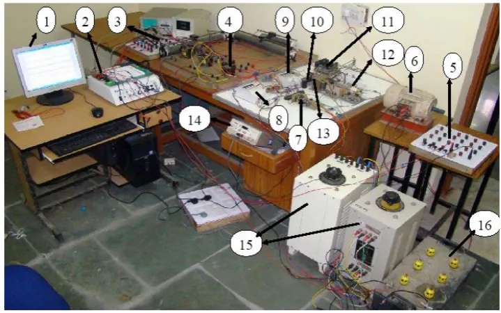
The hardware set up is shown in Figure 2. It consists of:
a) AC/DC converter section: This unit consists of uncontrolled three- phase diode bride rectifier.
www.ijaera.org 66 c) Energy Storage Devices: The device is a supercapacitor bank of 12V modules. This 12V
DC is converted to 220 V DC (for experimental purpose) with the help of buck-boost converter
d) Voltage Sag Generator Unit: The various types of faults were created in the lab using shunt impedance method by actually grounding/shorting the line terminals in order to represent the true voltage sag conditions as shown in Figure 1.
Figure 2. View of Designed Hardware.
1. Waveform in LabVIEW 9. AC/DC converter section 2. DAQ board 10.Capacitor bank(DC- link) 3. DC isolation circuit 11. Adjustable speed drives 4. Isolation transformer 12. Boost converter 5. Supercapacitor 13. DC- link 6. 3-phase induction motor 14. Function generator 7. Sag generator 15.3-phase Auto transformer 8. 3-phase supply 16. Battery
V. RESULT AND DISCUSSION
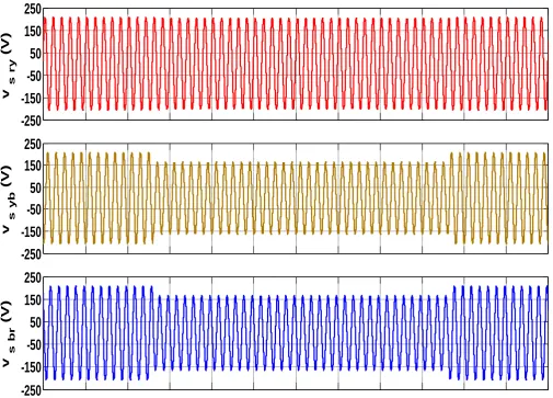
This section gives the performance of ASDs during unsymmetrical (single line to ground-Type-B) fault with and without supercapacitor as an energy storage devices across DC-Link to provide ride-through. At the terminals of three-phase motor observations are also taken to check the effect of various power quality disturbances. The performances of ASD have been simulated in MATLAB and the same was verified by experimental results.
A. Performance of ASDs during Single Line to Ground (Type-B) Fault without Ride-Through
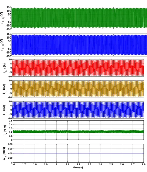
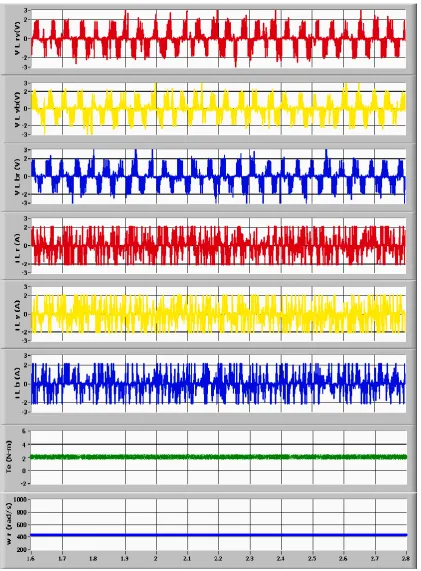
www.ijaera.org 67 electromagnetic torque (Te) and the speed (wr) of the Induction motor drops slightly as shown in
Figure 5 and Figure 6. The effective motor current during the fault period increases so as to maintain the desired torque as shown in Figure 5 and Figure 6.
-250
-150
-50
50
150
250
v
s
r
y
(V)
-250
-150
-50
50
150
250
v
s
y
b
(V)
-250
-150
-50
50
150
250
v
s
b
r
www.ijaera.org 68
-7.5 -5 -2.5 0 2.5 5 7.5
I s
r
(A)
-7.5 -5 -2.5 0 2.5 5 7.5
I s
y
(A)
-7.5 -5 -2.5 0 2.5 5 7.5
I s
b
(A)
1.6 1.7 1.8 1.9 2 2.1 2.2 2.3 2.4 2.5 2.6 2.7 2.8
175 200 225
v d
c
time(s)
www.ijaera.org 69 Figure 4. Experimental Results showing three-phase source voltages, currents and DC-Link voltage
www.ijaera.org 70 -150 -100 -50 0 50 100 150
v L
q (V) -150 -100 -50 0 50 100 150
v L
d (V) -10 -5 0 5 10
i L
a (A ) -10 -5 0 5 10
i L
b (A) -10 -5 0 5 10
i L
c (A ) 0 0.1 0.2 0.3 0.4 0.5 T e (N-m)
1.6 1.7 1.8 1.9 2 2.1 2.2 2.3 2.4 2.5 2.6 2.7 2.8
0 200 400 600 800 w r (rad /s) time(s)
www.ijaera.org 71 Figure 6. Experimental results showing three phase stator voltages, three-phase stator currents
www.ijaera.org 72 B. Performance of ASDs during Single Line to Ground (Type-B) Fault with supercapacitor as
Ride-Through alternative
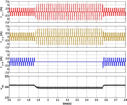
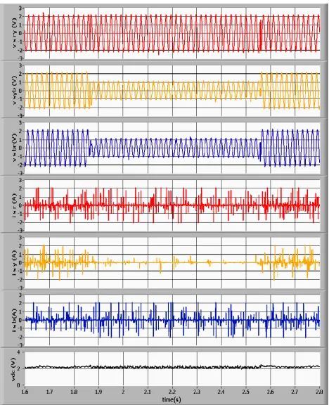
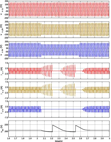
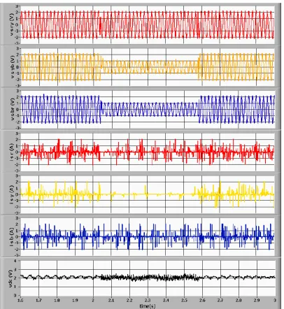
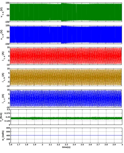
The simulation and hardware results, shown from Figure 7 to Figure 8 under unsymmetrical fault condition, are an example of voltage sag of Type-B (Line to Ground Fault) with supercapacitor as a ride-through capability connected across DC-Link through Boost Converter. A supercapacitor bank of 5 F, 13.5 V ( 25F, 2.7V , 5 Nos. connected in series ) The amplitude drops to a value of about 75% of the pre-event voltage during 2.05 to 2.58 sec about 27 cycles. The compensation provided by the supercapacitor bank is much faster as compared to other energy storage devices. The motor side three-phase voltages, currents, electromagnetic torque and rotor speed are also shown in Figure9 and Figure 10. The result shows the improvement in the current being drawn by the rectifier. A supercapacitor bank is able to provide required ride-through.
-250 -150 -50 50 150 250 v s ry (V) -250 -150 -50 50 150 250 v s y b (V) -250 -150 -50 50 150 250 v s b r (V) -7.5 -2.5 2.5 7.5
i s
r (A) -7.5 -2.5 2.5 7.5
i s
y (A) -7.5 -2.5 2.5 7.5
i s
b
(A)
1.6 1.7 1.8 1.9 2 2.1 2.2 2.3 2.4 2.5 2.6 2.7 2.8 2.9 3
200 225 v d c (V) time(s)
www.ijaera.org 73 Figure 8. Experimental results showing three-phase source voltages, currents and DC-Link voltage
www.ijaera.org 74
-150 -50 50 150
v L
q (V) -150 -50 50 150 v L d (V) -10 -5 0 5 10
i L
a (A) -10 -5 0 5 10
i L
b (A) -10 -5 0 5 10
i L
c (A) 0 0.125 0.25 0.375 0.5 T e (N-m)
1.6 1.7 1.8 1.9 2 2.1 2.2 2.3 2.4 2.5 2.6 2.7 2.8 2.9 3
0 200 400 600 800 w r (rad /s) time(s)
www.ijaera.org 75 Figure 10. Experimental results showing three phase stator voltages, three-phase stator currents,
electromagnetic torque and rotor speed during SLG fault (Type-B) with supercapacitor as ride-through alternative. Stator voltage scale: 100 V per division. Load current scale: 10 A per division. Electromagnetic Torque scale: 1 N-m per division. Rotor Speed scale: 1 rad/s per division.
VI. CONCLUSION AND FUTURE WORK
www.ijaera.org 76 Based on the above, the impact of other power quality issues on the process industries like food and beverages, paper, textile etc shall be studied and investigated through experiment work/simulation.
VII. REFERENCES
[1] G.T. Heydt, Electric Power Quality, 2nd ed. WestLafayette, Stars in a Circle, 1994. [2] Hingorani N, Gyugyi L, Understanding FACTS, Wiley IEEE Press, 1999.
[3] M. H. J. Bollen, “Understanding Power Quality Problems: Voltage Sags and Interruptions”, Series on Power Engineering. New York: IEEE Press, 2000.
[4] IEEE Recommended Practices on Monitoring Electric Power Quality, IEEE Std.1159, 1995.
[5] IEEE Recommended Practices for Evaluating Electric Power System Compatibility With Electronic Process Equipment, IEEE Std.1346, 1998.
[6] R.A. Epperly, F.L. Hoadley and R.W. Piefer, “Considerations when applying ASD’s in continuous processes,” IEEE Trans. on Industry Applications, vol. 33, no.2, pp. 389-396, March/April 1997.
[7] A. Z. Van. R. Spee, A. Faveluke and S. Bhowmik, “Voltage Sag Ride-Through for Adjustable-Speed Drives With Active Rectifiers”, IEEE Trans. on Industry Applications, vol. 34, issue 6, pp. 1270 – 1277, Nov.-Dec. 1998.
[8] A. Von, P.N. Enjeti, B. Banerjee, “Assessment of Ride-Through Alternatives for Adjustable-Speed Drives”, IEEE Trans. on Industry Applications, vol. 35, issue 4, pp. 908 - 916, July-Aug. 1999.
[9] J. L. D. Gomez, P.N. Enjeti, A. J. Von,”An Approach to Achieve Ride-Through of an Adjustable-Speed Drive with Fly back Converter Modules Powered by Super Capacitors”, IEEE Trans. on Industry Applications, vol. 38, issue 2, pp. 514-522, March-April 2002.
[10] Klumpner, C. and Blaabjerg, F, “Experimental evaluation of ride-through capabilities for a matrix converter under short power interruptions”, IEEE Trans. on Industry Applications, vol. 49, issue 2, pp. 315 – 324, April 2002.
[11] K. Lee, T.M. Jahns, D.W. Novotony, T.A. Lipo, W.E. Berkopec, and V. Blasko, “Impact of Inductor Placement on the Performance of Adjustable-Speed Drives Under Input Voltage Unbalance and Sag Conditions”, IEEE Trans. on Industry Applications, vol. 42, no. 5, pp. 1230-1240, Sept./Oct. 2006. [12] I. Boldea, “Control Issues in Adjustable Speed Drives”, IEEE Trans. on Industry Applications, pp.
32-50, Sep, 2008.
[13] F. D. Silva, A. J. J. Rezek, A. A. P Junior, L. E. B. D. Silva, P. C. Rosa, and L. O. M. Reis, “Supercapacitor-Based Ride-Through System for Adjustable Speed Drives Applied to Critical Process”, IEEE conference on Harmonics and Quality of Power, vol. 2, pp. 632-638, 2002.
[14] Y.R.L. Jayawickrama and S. Rajakaruna, “Supercapacitor Based Ride-Through System for a DC Load”, IEEE Conference on Power System Technology, vol. 1, pp. 232-237, 2004.
[15] K. Lee, T. M. Jahns, G. Venkataramanan,, “Modeling Effects of Voltage Unbalances in Industrial Distribution Systems With Adjustable-Speed Drives”, IEEE Trans. on Industry Appl., vol. 44 , Issue. 5 , pp. 1322 – 1332, 2008.
[16] S. Z. Djokic, K. Stockman, J. V. Milanovic, J. J. M. Desmet and R. Belmans, “Sensitivity of AC Adjustable Speed Drives to Voltage Sags and Short Interruptions”, IEEE Trans. on Power Del, vol. 20, Issue. 1, pp. 494–505, 2005.
[17] M. H. J. Bollen, L. D. Zhang,“Analysis of VoltageTolerance of AC Adjustable-Speed Drives for Three-Phase Balanced And Unbalanced Sags”, IEEE Transactions on Industry Applications, vol. 36 , Issue. 3, pp. 904- 910, 2000.
[18] J. Pedra, F. Corcoles, F. J. Suelves, “Effects of Balanced and Unbalanced Voltage Sags on VSI-Fed Adjustable-Speed Drives”, IEEE Transactions on Power Delivery, vol. 20, Issue. 1, pp. 224-233, 2005. [19] V. B. Bhavaraju and P. N. Enjeti, “An Active Line Conditioner to Balance Voltages in a Three-Phase
System,” IEEE Trans. Industry Applications, vol. 32, no. 2, pp. 287-292, Mar./Apr. 1996.