e-ISSN: 2278-067X, p-ISSN: 2278-800X, www.ijerd.com
Volume 12, Issue
10
(
October
2016), PP.35-43
Analysis of Static and Dynamic Strength of Al Based MMCS
Used As A Skin of High Speed Aerospace Vehicle
S Sapthagir
1, Dr K Jayathirtha Rao
21Associate Professor, Guru Nanak Institutions Technical Campus, Hyderabad, Telangana. 2Director (Retd) Environmental Test Facility, RCI, Hyderabad, India.
Abstract:-The materials behaviour is very typical in nature under the dynamic loading, since it depends on size and geometry of a component, surrounding environment of the component, non-homogeneity of the material. Experimental set-up for the analysis of materials which used as a skin of aerospace vehicle is very expensive and time consuming. Therefore another alternative method is simulation codes like LS-DYNA. LS-DYNA is a finite element code that gives an approximation towards the solution. Simulation of impact phenomenon requires a numerical approach that allows one body (fragment) to pass through another body (target). The aim of the present work is to study the damage behavior of different plate materials with different thicknesses subjected to impact loads, by using explicit finite element code LS-DYNA. In this project, target plates of 3mm and 6mm thickness of materials Titanium and Aluminium alloys are made to impact by Tungsten fragment with different velocities 300, 500, 700 and 1000 mm/milli-sec. Different kinetic energy and residual velocity of fragments against time, graphs are plotted to analyze the damage on different target plates. It is observed that the element size significantly affects the numerical results; therefore a sufficiently refined mesh was used. Keywords:- Structural analysis of wings with fuselage, Dynamic analysis by LS-DYNA
I.
INTRODUCTION
This document is a template. An electronic copy can be downloaded from the conference website. For questions on paper guidelines, please contact the publications committee as indicated on the website. Information about final paper submission is available from the website.
The response of any structural element, when subjected to dynamic (impact) loading such as projectile hitting a target is significantly different compared to its response to a static force. Dynamic strength characteristics of projectile/target undergo considerable changes due to impact. When the impact is made with high velocities, projectile and target experience plastic deformation, material failure, and decrease in strength, cracks formation and propagation etc. All these effects need to be accounted in numerical simulation tools in order to get accurate representation of the actual behaviour.
LS-DYNA is a general-purpose finite element code for analyzing the large deformation, dynamic response of structures including structures coupled to fluids. The methodology of this work is based on explicit time integration.
Special discretization is achieved by the use of four node tetrahedron and eight node solid elements, two node beam elements, three and four node shell elements, eight node solid shell elements, truss elements, membrane elements, discrete elements and rigid bodies. A variety of element formulations are available for each element type. LS-DYNA currently contains approximately one hundred constitutive models and ten equation of state to cover a wide range of material behavior. For the present work two constitutive models are chosen which exhibits strain rate effects.
Target damages when target is subjected to impact load by high velocities of fragment. The damage to the target depends on various factors such as:
the geometric shape of the fragment and Target the geometric size of the fragment and Target the material of the fragment and Target the number of fragments hitting the target the velocity of the fragment
the angle of hit with the normal direction of the target the thickness of target
II.
METHODOLOGY
AND
ANALYSIS
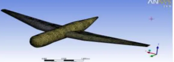
Creating geometric modelIn this work ANSYS software was used as the processor and postprocessor. The pre-processing task includes building the geometric model and defining the relevant material properties, applying the boundary conditions and loading conditions. The figure 1 shows the geometric model of the plane which was used to analyse the static and dynamic strength of the al based MMCs materials.
Fig. 1: Geometric Model of the plane
Meshing
Mesh size plays a very important role in the accuracy of the results. Choosing appropriate element type and the mesh size is utmost important. With increase in mesh quality and size, results tend to converge and stabilize. Lot of effort has gone in choosing the appropriate element type and mesh size for this impact study. The mesh was refined in the impact zone. The mesh density was reduced as the distance from the impact area increased. Care was also taken to maintain correct aspect ratio in the grid especially in and around the impact zone where the aspect ratio of the elements was maintained close to unity. The aspect ratio was allowed to increase towards the periphery of the plate. The geometry with discretisation is shown in figures 4.1 to 4.3 displaying different views.
Fig. 2: meshing of the geometrical model of the plane
Following are the quality checks maintained for elements.
Warpage - 5
Skew - 60
Aspect - 5
Length - 1.5
Jacobian - 0.7
Mesh type - quads
Max angle - 135
Min angle - 45
When any node is not coplanar to other nodes of a 2D element, warpage is occurred. It is eliminated by dividing into two trias (triangles). Skew is calculated by finding the minimum angle between two lines joining opposite mid-sides of the element.
Material properties
Table No I. The mechanical properties of the target materials.
Properties Density Kg/mm3
Young’s Modulus KN/mm2
Poisson’s Ratio
Yield Stress KN/mm2
Failure Strain
Cowper Symonds strain rate parameters
C P
Types of material
Al
Alloy 2.8E-06 73.08
0.33
0.339896 0.113 6500 4
Ti
Alloy 4.47E-06 110.32 0.3 0.82737 0.015
120 9
Fig. 3: Stress- Strain curve for Al Alloy
Fig. 4: Stress-Strain curve for Ti Alloy
Appling boundary and loading conditions
The figure 5 shows the finite element model after applying the boundary conditions.
Fig. 5: Finite element model with boundary conditions
Structural analysis
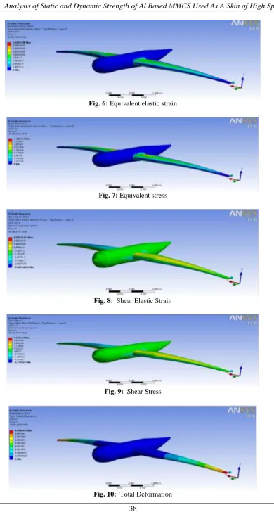
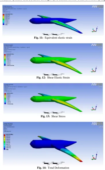
The different composition of Al based MMCs material were used to analysis dynamic strength adoptability for the High Speed Aerospace vehicle. The sample no.1 and 2 metal composition are Al6061+TiB2+Ni+Fly ash and Al6062+Ni+ TiB2 respectively. The figures no 6 to 10 shows the snap shots of the ansys results with metal comosition is Al6061+TiB2+Ni+Fly ash and figures no 11 to 13 shows the snap
Fig. 6: Equivalent elastic strain
Fig. 7: Equivalent stress
Fig. 8: Shear Elastic Strain
Fig. 11: Equivalent elastic strain
Fig. 12: Shear Elastic Strain
Fig. 13: Shear Stress
Fig. 14: Total Deformation
III.
CASE
STUDIES
Fig. 15: Isometric view of target (hollow cylindrical cone)
Different gap between plates
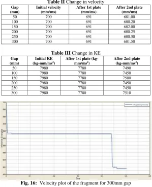
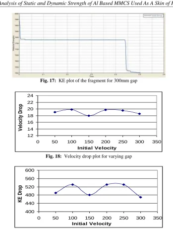
In this section, results of 18 case studies are shown where a 15 mm cube shaped tungsten fragment is made to impact with a velocity of 700mm/ms onto two Titanium target plates of size 300x300x3 mm by varying gap of 50, 150, 200, 250 and 300mm between two plates. The fragment is positioned at a distance of 0.5mm from the first target plate for all cases. It is observed that the fragment penetrated easily through two plates by reducing its velocity and kinetic energy. Figures from 5.55 to 5.64 show the corresponding plots for cases 15 to 19 analyzing velocity and kinetic energy of the fragment. The velocity and kinetic energy results obtained are listed in the tables II and III. Velocity and kinetic energy values for 100mm gap between plates are taken from case 7 of section 5.2 as it is similar one.
Table II Change in velocity
Gap (mm)
Initial velocity (mm/ms)
After 1st plate (mm/ms)
After 2nd plate (mm/ms)
50 700 691 681.00
100 700 691 680.20
150 700 691 682.00
200 700 691 680.25
250 700 691 680.50
300 700 691 681.50
Table III Change in KE Gap
(mm)
Initial KE (kg-mm/ms2)
After 1st plate (kg-mm/ms2)
After 2nd plate (kg-mm/ms2)
50 7980 7780 7490
100 7980 7780 7450
150 7980 7780 7500
200 7980 7780 7450
250 7980 7780 7450
300 7980 7780 7510
Fig. 16: Velocity plot of the fragment for 300mm gap
Fig. 17: KE plot of the fragment for 300mm gap
12 14 16 18 20 22 24
0 50 100 150 200 250 300 350
Initial Velocity
V
el
o
ci
ty
D
ro
p
Fig. 18: Velocity drop plot for varying gap
400 440 480 520 560 600
0 50 100 150 200 250 300 350
Initial Velocity
K
E
D
ro
p
Fig. 19: KE drop plot for varying gap Multi fragment impact
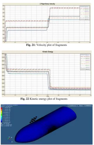
This is a last case 20 where, nine, 15mm cube shaped fragments are made to impact with a velocity of 700mm/ms onto hollow cylindrical cone of 290mm diameter with 2.5mm thickness. The fragments are positioned at a distance of 2.5mm from the target. At the impact zone fine mesh is considered as shown in the close view in the figure 20. Figures 21 and 22 show the velocity and kinetic energy plot of each fragment. The Vonmises stress plots are shown in the figures 23 describing after impact.
Fig. 21: Velocity plot of fragments
Fig. 22 Kinetic energy plot of fragments
Fig. 23: Snap shot of hollow cylindrical cone after impact
IV.
DISCUSSIONS
Torsional stress in a fuselage is created in several ways. For example, torsional stress is encountered in engine torque on turboprop aircraft. Engine torque tends to rotate the aircraft in the direction opposite to the direction the propeller is turning. This force creates a torsional stress in the fuselage. Also, torsional stress on the fuselage is created by the action of the ailerons when the aircraft is maneuvered. When an aircraft is on the ground, there is a bending force on the fuselage. This force occurs because of the weight of the aircraft. Bending increases when the aircraft makes a carrier landing.
impact velocities between the plate with different KE. It has been observed that alloy materials shows good results when compare with before researches did.
Although these concept avoids some of the questions surrounding aircraft design for low sonic boom by flying sub sonically overland, many interesting configurations have been developed recently to reduce sonic boom overpressure. Designs by most of the major business jet manufacturers include configurations with retractable nose booms, very long aircraft concepts, and joined wings.
The mechanism discovered is the turbulent wake coupling to the parachute’s bow-shock causing it to change shape and standoff distance, resulting in depressurization of the canopy and resultant partial collapse. Following disruption of the bow shock the canopy re-pressurizes and the process repeats itself in a cyclical manner.
V.
CONCLUSIONS
The deformations caused due to various impact velocities for different materials were analyzed. It has been found that velocity drop is increased as the impact velocity is increased.
The kinetic energy drop is increased by the increment of velocity i.e. energy absorption is more for higher velocities.
ACKNOWLEDGMENT
At the outside, I sincerely thank and extend my gratitude to the management of Guru Nanak Institutions Technical campus, Ibrahimpatanam, RR District, Hyderabad for constant encouragement for carrying out experiments and publications of technical paper.
REFERENCES
[1]. S. M. Metev and V. P. Veiko, Laser Assisted Microtechnology, 2nd ed., R. M. Osgood, Jr., Ed. Berlin, Germany: Springer-Verlag, 1998.
[2]. Jiyu Sun, Bharat Bhushan, The structure and mechanical properties of dragonfly wings and their role on fly ability C. R. Mecanique 340, pp 3 – 17, 2012.
[3]. Walker, S. H. and Rodgers, F., “Falcon Hypersonic Technology Overview,” AIAA Paper 2005-3253, May 2005.
[4]. Bisplinghoff, R. L., “Some Structural and Aeroelastic Considerations of High-Speed Flight,” Journal of the Aeronautical Sciences, Vol. 23, No. 4, April 1956, pp. 289–329.
[5]. DeJarnette, F. R., Hamilton, H. H., Weilmuenster, K. J., and Cheatwood, F. M., “A Review of Some Approximate Methods Used in Aerodynamic Heating Analyses,” Journal of Thermophysics and Heat Transfer Vol. 1, No. 1, January 1987, pp. 5–12.
[6]. W Kuntjoro, AMH Abdul Jalil, J Mahmud, Wing Structure Static Analysis using Super element, Procedia Engineering 41,pp 1600 –1606, 2012.
[7]. T. Borvik, M. Langseth, O.S. Hopperstad, K.A. Malo, Ballistic penetration of steel plates, Int. J. Impact Engng, 22, 855-886, 1999
[8]. A.A. Almohandes, M.S. Abdel-Kader, A.M. Eleiche, Experimental investigation of the ballistic resistance of steel-fiberglass reinforced polyester laminated plates, Composites: Part B, 27 B, 447-458, 1996
[9]. M.J. Thali, B.P. Kneubuehl, U. Zollinger, R. Dirnhofer, A high speed study of the dynamic bullet-body interactions produced by grazing gunshots with full metal jacketed and lead projectiles, Forensic Science International 132, 93-98, 2003
[10]. L.M. Wilkins, M.W. Guinan, Impact of cylinders on a rigid boundary, J. Appl. Phys, 44(3), 1200-1206, 1973
[11]. J.E. Hockett, N.A. Lindsay, Cam plastometer data acquisition system, J. Phys. E: scientific instruments, 4, 520-522, 1971
[12]. D.L. Orphal, R.R. Franzen, A.J. Peikutowskf, M.J. Forrestal, Penetration of confined aluminium nitride targets by tungsten long rods at 1.5-4.5 km/s, Int. J. Impact Engng, 18(4), 355-368, 1996
[13]. D.S. Preece,V.S. Berg, Bullet impact on steel and Kevlar/steel armor - computer modelling and experimental data, Proceedings of ASME symposium, July 25-29, 2004
[14]. C.E. Anderson Jr., V. Hohler, J.D. Walker, A.J. Stilp, Time-resolved penetration of long rods into steel targets, Int. J. Impact Engng, 16(1), 1-18, 1995