Abstract—The coupled model of human and structure system has been developed by considering the standing human body as an elastic non-uniform column with the distributed mass, damping and stiffness. The governing differential equations of the human-beam system and the human-plate system are, respectively, derived by using the Lagrange equation. A two-section elastic column is used to simulate the vibration of the human body. The dynamic characteristics of the human-structure interaction are analyzed by the use of the complex mode theory. The influence of the human standing on the beams or the plates on vibration characteristics of the coupled systems is investigated in detail. The numerical results are compared with the experimental ones existed in the literature, good agreement has been achieved. Therefore, the reasonability and correctness of the present model have been demonstrated.
Index Terms—Body model, dynamic characteristic, dynamic differential equations, human-structure coupled system.
I. INTRODUCTION
In recent years, an increasing number of problems related to human-induced vibrations of floors, footbridges, assembly structures and stairs are reported. There are several reasons for that, such as: (1) improved mechanical properties of structural materials leading to reduced structural mass, (2) increased length of structural spans leading to increased slenderness, and (3) aesthetic design requirements for eye-catching ‘transparent’ structural forms. The factors mentioned above usually lead to very lightweight structures with light damping. In such a case, the vibration excited by the crowd’s activity should be considered because it results in the uncomfortable feeling of the presence crowd and/or results in the damage of the structure. Therefore, through the study on the human occupants-structure interaction, not only the safety problems of structure could be solved, but also the human’s comfort problems under the structure vibration could be reduced.
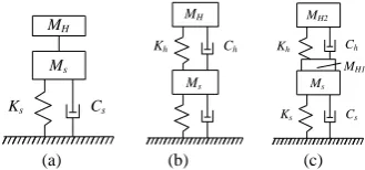
The existing knowledge of human-structure interaction can be summarized as two key aspects: (1) how structural vibrations can influence forces induced by human occupants, and (2) how human occupants influence the dynamic properties of civil engineering structures. When the influence of human occupants on the dynamic properties of civil engineering structures is considered, occupants are often modeled just as additional mass to the structure (Fig. 1(a)). This model has been widely accepted for a long time.
Manuscript received December 6, 2016; revised May 2, 2017. The financial supports from the National Natural Science Foundation of China (11372127) and the Key Program of Natural Science Research of Jiangsu Provincial University, China (12KJA580002) are greatly acknowledged.
Huixuan Han and Ding Zhou are with the College of Civil Engineering, Nanjing Tech University, No. 30 Puzhou Road(S), China (e-mail: [email protected], [email protected]).
Naturally, such a model leads to a frequency decrease. However, experimental study demonstrates that occupants also have the potential to increase existing natural frequencies and even create new vibration modes [1], [2]. Furthermore, it is widely acknowledged that human occupants increase damping of civil engineering structures [3], [4]. This just as additional mass of modeling humans cannot explain observed increases of natural frequencies, or the appearance of additional natural frequencies. Furthermore, it is difficult to use this model to explain the significant increase in damping observed in real life. This insufficiency has led to the proposal of a single degree-of-freedom (SDOF) occupant model (Fig. 1(b)). Modeling a human body as a SDOF system on a structure is simple and popular and the parameters of the body models, such as mass, stiffness, damping ratio and natural frequency for individuals have been defined through shaking-table experiments and the best curve fitting between the measured apparent mass and SDOF or TDOF models [5]-[8].
It is gradually realized that modeling the human body as an isolated SDOF system or a crowd as an isolated distributed SDOF system and then placing the SDOF body system on a structure maybe is not the best approach for the study of human-structure interaction, see Fig. 2(b). Instead, a standing person can be modeled as an elastic non-uniform column with the distributed mass, damping and stiffness placed on the structure and only the fundamental vibration mode of the column is considered (Fig. 1(c)). This finding could lead to the new coupled model of human-structure interaction.
The present study uses the Lagrange equation to derive the governing differential equations of the human-beam system and the human-plate system, respectively. A two-section elastic column is taken to simulate the vibration of the human body. Then a multi-degree of freedom coupled system is developed. The dynamic characteristics of the human-structure interaction are analyzed by the use of the complex mode theory. The influence of the human standing on the beams or the plates on vibration characteristics of the coupled systems is investigated in detail.
II. THE GOVERNING DIFFERENTIAL EQUATIONS OF THE
HUMAN-BEAM SYSTEM
Consider bodies of height of H on a non-uniform slender beam system as shown in Fig. 2 where the same physical parameters for all bodies are assumed for the simplicity in the analysis however without losing the generality. A lot of experimental investigations show that the fundamental frequency of the body plays a main role in the human-structure coupled vibration. Therefore, only the fundamental mode of the body vibration is considered in the present analysis. Here, the mechanical property of the body
The Modeling of Human-Structure Interaction
is described by an elastic column with variable mass m(y), stiffness k(y) and damping c(y) distributions. The displacement
u
Hj( , )
y t
of the jth body on the beam can be expressed as:( , )
( , )
( , )
Hj s j R j
u
y t
u x t
u
y t
(1)( , )
( )
( )
s j HRj H
u x t
u
t
y
in which,1
( , )
( )
( )
s n n
n
u x t
x q t
u
s( , )
x t
is the displacement of the beam.
n( )
x
is thenth modal function of the beam.
u
Rj( , )
y t
is the relativedisplacement of the jth body to the beam.
H( )
y
is the fundamental modal function of the body.MH
Ms
Ks Cs
MH Kh Ch
Ms
MH1
Ms
Ks Cs
MH2
Kh Ch
(a) (b) (c) Fig. 1. Available models of human body on a SDOF platform.(a) Mass-only
human-body model, (b) SDOF human-body model and (c) SDOF model with a non-vibrating mass.
The potential energy of the human-beam system is
2 2 0 1 1
( )
( )
( )(
)
J L ns Hj n
j n
d
x
U
U
U
q t
k x
dx
dx
2 2 0 1( )
1
( )(
)
2
J H H HRj j jd
y
u
k y
dy
dy
(2a)The kinetic energy of the coupled system is
2 0 1 1
1
( )[ ( ) ( )]
2
J Ls Hj n n
j n
T
T
T
m x
x q t
dx
2 0 11
( )[ ( , )
( )
( )]
2
J Hs j HRj H
j
m y u x t
u
t
y
dy
(2b)The dissipated energy of the coupled system is
2 2 0 1 1
1
( )( )
( ) ( )
2
J Ls Hj n n
j n
R
R
R
q t t
c x
x dx
2 2 0 11
( )
( )
( )
2
J H HRj H ju
t
c y
y dy
(2c)where
k x
( )
,m x
( )
andc x
( )
is variable mass, stiffness and damping distributions of the beam, respectively.For the free vibration, the Lagrange equation is:
(
)
0
n n n
d
T
U
R
dt
q
q
q
( n=1,2,…, N ), (3a)(
)
0
HRj HRj HRj
d
T
U
R
dt
u
u
u
( j=1,2,…, J ) (3b)Substituting (2a)-(2c) into (3a) and (3b) gives the governing differential equations in a matrix form as follows:
[
M
]
X
[ ]
C
X
[ ]
K
X
0
(4) in which:
[ ,
1 2,
,
,
1,
2,
]
T
N HR HR HRJ
X
q q
q u
u
u
(5a)
2
1 1 1 1 1 2 1
1
2
2 2 2 1 2 2 2
1
2
1 2
1
1 1 2 1 1
1 2 2
( ) 0 ( ) ( ) ( )
0 ( ) 0 ( ) ( ) ( )
0 0 ( ) ( ) ( ) ( )
( ) ( ) ( ) 0 0
( ) (
J
j T HS HS J HS
j
J
j T HS HS J HS
j
J
N N j T N HS N HS N J HS
j
HS HS N HS H
HS
M x M x M x M x M
M x M x M x M x M
M
M x M x M x M x M
x M x M x M M
x M x
2 2 1 2) ( ) 0 0
( ) ( ) ( ) 0 0
HS N HS H
J HS J HS N J HS H
M x M M
x M x M x M M
(5b)
1 1 1
2 2 2
2
0
0
0
0
0
2
0
0
0
0
0
2
0
0
0
0
0
0
2
0
0
0
0
0
0
2
0
0
0
0
2
N N N
H H H
H H H
H H H
2
1 1
2
2 2
2
2
2
2
0 0 0 0
0 0 0 0
0 0 0 0 0
0 0 0 0 0
0 0 0 0 0
0 0 0
N N
H H
H H
H H M
M
M K
M
M
M
(5d)
where
M
n,
n and
n (n=1, 2, … N) are the ith modal mass, corresponding frequency and damping ratio of the bare beam, respectively.
H and
H are the individual body frequency and damping ratio, respectively.2 0
( ) ( )
L
n n
M
m x
x dx
( n=1,2,…, N ) (6a)0
( )
H T
M
m y dy
(6b)0
( )
( )
H
HS H
M
m y
y dy
(6c)2 0
( )
( )
L
H H
M
m y
y dy
(6d)where
M
T is the total mass of the body,M
H is the modal mass of the body andM
HS is the coupled mass of the body and structure. The coupled system leads to N+J modes of vibration. Each mode is defined by its complex eigenvalue
r(r=1,2,…, N+J) and complex mode shape
r. The complex eigenvalue
r defines the (damped) natural frequenciesf
r and the damping ratios
r:1
2
r r
f
, lRe(
r)
r
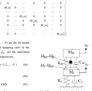
(r=1, 2,…, N+J) (7)When only one person stands on the beam and only the fundamental mode of the beam are considered, a simple physical model can be given in Fig. 3 where the mass (
M
HS
M
H) is attached toM
H however makes the relative motion toM
s , i.e., the acceleration of (M
HS
M
H) is equal tou
h
u
s. Comparing to Fig. 1(b), one can clearly see the difference between the present human-structure model and the conventional human-structure model.Fig. 2. The model of human-beam system.
Fig. 3. The coupled physical model of single degree of freedom structure and single degree of freedom person.
III. THE GOVERNING DIFFERENTIAL EQUATIONS OF THE
HUMAN-PLATE SYSTEM
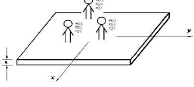
Consider bodies of height of H on a uniform thin plate system as shown in Fig. 4. For simplicity and convenience in mathematical formulation, the following non-dimensional parameters are introduced:
2
x a
,
2
y b
(8)The mechanical property of the body can be described by an elastic column with the variable mass m(y), stiffness k(y) and damping c(y)distributions as given in the last section. The displacement wHj (x, y, t) of the jth body on the plate can be expressed as:
( , , ) ( , , ) ( , )
Hj j j R j
w
t w
t w z t
w
(
j,
j, )
t
w
H R j( )
t
Hz
( )
(9) where j means the jth body on the beam and J is the total number of body on the plate.w
( , , )
t
is the plate displacement and can be represented as [9]:1 2
1 1
( , , )
w( )
w( )
i( ) ( )
j kl( )
k l
w
t
f
f
P
P
A t
(10)where
P
s( )(
s
i j
, ;
, )
is the one-dimensional sth Chebyshev polynomial [9] which can be written in terms of cosine functions as follows:... ...
x1
xj
xJ
L m(y),
k(y), c(y)
m(y), k(y), c(y)
m(y), k(y), c(y)
( )
cos[(
1) arccos( )]
s
P
s
(
s
1, 2,3,
)
(11)It should be noted that
f
w1( ) and
f
w2( )
are the boundary characteristic functions corresponding to different boundary conditions, as given in Table I [9].The potential energy of the human-plate system is
1
J
s Hj
j
U
U
U
2 2 2 2 2
1 1 2
2 2 2 2 2 2 2 2
1 1
4 4 32(1 )
[( ) [ ]
2
D w w w w w
d d
a b a b
2 2 0 1( )
1
( )
( )(
)
2
J H H HRj j jd
z
w
t
k z
dz
dz
(12a) The kinetic energy of the coupled system is
1
J
s Hj
j
T
T
T
=1 1 2 1 1
(
)
8
ab h
w
d d
t
+ 2 0 1(
,
, )
( )
1
( )[
( )]
2
J Hj j HRj
H j
dw
t
dw
t
m z
z
dz
dt
dt
(12b)The dissipated energy of the coupled system is
1
J
s Hj
j
R
R
R
1 1
2 2 2
1 1 0
1
1
( , )(
)
( )
( ) ( )
8
2
HRjJ H
H j
ab h
w
c
d d
w
t
c z
z dz
t
(12c)For the free vibration, the Lagrange equation is:
( )
( ) ( ) ( ) n
kl kl kl
d T U R
Q dt A t A t A t
(k=1, 2 …K; l=1, 2…L) (13a)
(
)
jHRj HRj HRj
d
T
U
R
Q
dt
u
u
u
(j=1, 2 …J) (13b)Substituting (12a)-(12c) into (13a) and (13b) gives the governing differential equations in a matrix form as follows:
[
M
]
X
[ ]
C
X
[ ]
K
X
0
(14) in which:
THRJ HR
HR
kl
u
u
u
A
A
A
X
11,
12,
,
,
1,
2,
,
(15a)
1,1 1,1 1,1
1,2 1,2 1,2
, , ,
2 0 0 0 0
0 2 0 0 0
0 0 2 0 0 0
0 0 0 2 0 0
0 0 0 0 2 0
0 0 0 2
K L K L K L
H H H
H H H
H H H M M M C M M M (15b)
2 1,1 1,1 2 1,2 1,2 2 , , 2 2 20 0 0 0
0 0 0 0
0 0 0 0 0
0 0 0 0 0
0 0 0 0 0
0 0 0
K L K L
H H H H H H M M M K M M M
(15c) in which,
z
dz
m
M
T
H0
(16a)
z
z
dz
m
M
HS
H
H0 (16b)
z
z
dz
m
M
H H H 2 0
(16c)
d
d
P
P
f
f
h
ab
M
kl 1 w w2 k l 21 1
1 1 ,
4
(
k
1, 2,
K l
;
1, 2
L
)
(16d))
(
)
(
)
(
)
(
)
,
(
1 2,l j j w j w j k j l j
k
f
f
P
P
(
k
1, 2,
K l
;
1, 2
L j
;
1, 2,
J
)
(16e)The coupled system leads to (K×L+J) modes of vibration. Each mode is defined by its complex eigenvalue
r(r=1, 2, … K×L+J) and the corresponding complex mode shape
r.1
2
r r
f
,Re(
r)
l
r
(r=1, 2,…, K×L+J) (17)TABLEI:BOUNDARY CHARACTERISTIC FUNCTION COMPONENTS FOR DIFFERENT BOUNDARY CONDITIONS
Boundary conditions 1
( )
w
f fw2( )
F-F 1 1
F-S 1–α 1–β
S-F 1+α 1+β
S-S 1–α2 1–β2
F-C (1–α)2 (1–β)2 C-F (1+α)2 (1+β)2
S-C (1+α) (1–α)2 (1+β) (1–β)2
C-S (1–α) (1+α)2 (1–β) (1+β)2
C-C (1–α)2 (1+α)2 (1–β)2 (1+β)2
Note: F: free edge, S:simply-supported edge, C: clamped edge.
Fig. 4. The model of human-plate coupled system.
IV. MODAL PARAMETERS OF BODY
According to the knowledge of biomechanics, the body can be simply modelled as a bar with two segments [10] as given in Fig. 5. The mass and longitudinal stiffness per unit length are the constants along each segment and the equation of axial motion is
2 2
2 2
0
i i
i i
i
u
u
m
k
t
x
, (i=1,2) (18)
where
m
i andk
i (i=1,2) are the mass and longitudinal stiffness densities of each segment. The solution of the above equation has the following form:( , )
sin(
)
( )
i i i
u x t
A
t
x
, i=1,2 (19)where
is the radian frequency,
i is the phase angle,( )
i
x
is the mode shape function and A is the magnitude of vibration. Using the end conditions of the body and the consistent conditions at the connection of two parts, the modal shape functions of the body are1 1 1 1 1 1
1 1
2 2 1 1 2 2 1 1 2 2 2 2
2 2
( ) sin , 0 ,
( ) [sin cos cos sin ], 0
x D b x x L
m k
x D b L b x b L b x x L
m k
(20)
where
b
1
k m
1/
1 ,b
2
k
2/
m
2 , D is the constant and determined bymax
( )
x
1
.The frequency equation is
tan
b L
tan
b L
m k
m k
1 1 2 2
1 1 2 2
(21)where
b L
2 2
b L
1 2k m
1 2/(
k m
2 1)
.It is well known that to exactly give the mass and stiffness distributions is unpractical because the complicity of body. In the present study, four cases of mass and stiffness distributions of the body are studied and
L
2
L
1 is taken. The corresponding modal parameters are given in Table II.TABLEII:THE MODAL PARAMETERS OF THE BODY MODELS
Cases Mass and stiffness MHS MH
1 m2=2m1, k2=0.5k1 0.6366MT 0.5000 MT
2 m2=2m1, k2=k1 0.7108 MT 0.5894 MT
3 m2=2m1, k2=2k1 0.7659 MT 0.6667 MT
Fig. 5. The model of body vibration in vertical direction.
V. AN EXAMPLE
To illustrate the use of the present model, an examples of human-beam interaction are analyzed. The example is a simply-supported beam of length 11.0 m, width 1.25 m and thickness 0.35 m [11], [12]. The material properties of the beam are mass density, ρ =2400 kg/m3 and Young’s modulus, E = 30×109 N/m2. We only consider the first three vibration modes of the bare beam in the analysis. The natural frequency of the bare beam is f14.5Hz ,
2 18
f Hz
. The damping ratios of the bare beam are
1 0.3%
,
20.075% . The effective body masscontributing to vibration is considered to be the Case 3 in Table Ⅱ with the fundamental natural frequency of 5.5 Hz [13], [14], the body mass of 70 kg and the body damping ratio of
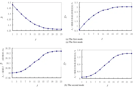
H 0.42. Figure 6 gives the damped natural frequencies and the damping ratios of the human-beam system with respect to the position,x
1 of single human athuman-beam system with respect to the human number J in the interval (1, 23) where the human standing on the beam begins from the mid-span of the beam with a 0.5 m distance each other. In this case, the max number of human on the beam is 23. It is shown that the frequency of the first mode generally decreases with the increase of the human number and the frequency of the second mode and the third mode increases with the increase of human number. The damping
ratio of the first mode to third mode increases with the increase of human number.
The numerical results are compared with the experimental ones given in the literature [12], [13], as presented in Table 3. It is shown that a good agreement has been achieved. Therefore, the reasonability and correctness of the present model have been demonstrated.
(a) The first mode
(b) The second mode
Fig. 6. The position effect of single human on the dynamic characteristics of human-beam system.
(a) The first mode (a) The first mode
(b) The second mode
Fig. 7. The effect of human number on the dynamic characteristics of human-beam system.
4.475 4.48 4.485 4.49 4.495 4.5
0 1 2 3 4 5 6 7 8 9 10 11
单个人的位置/m
人—
梁联合体系
1
阶频率
/
Hz
0.3 0.35 0.4 0.45 0.5 0.55 0.6
0 1 2 3 4 5 6 7 8 9 10 11
单个人的位置/m
人—梁联合体系1
阶阻尼比/
%
18 18.004 18.008 18.012 18.016 18.02
0 1 2 3 4 5 6 7 8 9 10 11
单个人的位置/m
人—
梁联合体系
2
阶频率
/
Hz
0.075 0.1 0.125 0.15 0.175 0.2
0 1 2 3 4 5 6 7 8 9 10 11
单个人的位置/m
人—梁联合体系2
阶阻尼比/
%
4.25 4.3 4.35 4.4 4.45 4.5
1 3 5 7 9 11 13 15 17 19 21 23
梁中点对称布置人的数目/个
人—梁联合体系1
阶频率/
H
z
0.5 1 1.5 2 2.5 3 3.5
1 3 5 7 9 11 13 15 17 19 21 23
梁中点对称布置人的数目/个
人—梁联合体系1
阶阻尼比/
%
17.95 18 18.05 18.1 18.15 18.2 18.25
1 3 5 7 9 11 13 15 17 19 21 23
梁中点对称布置人的数目/个
人—梁联合体系2
阶频率/
H
z
0 0.4 0.8 1.2 1.6
1 3 5 7 9 11 13 15 17 19 21 23
梁中点对称布置人的数目/个
人—梁联合体系2
阶阻尼比/
%
x1 x1
x1 x1
1
2
J J
2
2
J J
1
2
1
1
TABLEIII: COMPARISONS OF THE EXPERIMENTAL RESULTS AND THE
PRESENT NUMERICAL RESULTS
Human number
The first frequency /Hz The first damping ratio Present Experiment Present Experiment 1 4.479Hz decrease
trend
0.60% 0.6%
5 4.362Hz 1.68% 1.7%
VI. CONCLUSIONS
This paper derived the governing differential equations of the human-beam system and the human-plate system by using the Lagrange equation, respectively. A two-section elastic column is used to simulate the vibration of the human body. The influence of the human standing on the beams or the plates on vibration characteristics of the coupled systems is investigated in detail. The main conclusions are summarised as follows:
1) A new human-structure model is developed, which is more reasonable than the conventional one. In the new model, the human body is considered as an elastic column on the structure. The difference between the present model and the conventional model can be clearly seen by comparing Fig. 3 and Fig. 2(b) where the term of the relative inertia force, (MHSMH) (uhus), is not existed.
2) The numerical results are compared with the experimental ones given in the literature, good agreement has been achieved. Therefore, the reasonability and correctness of the present model have been demonstrated.
3) In the analysis, the frequency of the first mode of human-beam system generally decreases with the increase of the human number. However, the frequency of the second mode and the third mode increases with the increase of the human number. The damping ratios of the first three modes increase with the increase of the human number. Therefore, the effect of human body on structural vibration characteristics is different for the different modes.
REFERENCES
[1] T. Ji, “Understanding the interactions between people and structures,”
The Structural Engineers, vol. 81, pp. 12-13, July 2003.
[2] J. H. Rainer and G. Pernica, “Damping of a floor sample,” The Second Specialty Conference on Dynamic Response of Structures: Experimentation, Observation, Prediction and Control, pp. 859-873, Atlanta USA, 1981.
[3] A. Polensek, “Damping capacity of nailed wood-joist floors,” wood science,vol. 8, pp. 140-151, March 1975.
[4] J. H. Rainer and G. Pernica, “Damping of a floor sample,” in Proc. the Second Specialty Conference on Dynamic Response of Structures:
Experimentation, Observation, Prediction and Control, pp. 859-873, Atlanta USA, 1981.
[5] B. R. Ellis and T. Ji, “Human-structure interaction in vertical vibrations,” in Proc. ICE: Structure and BuildingsConf., 1997, pp. 1-9.
[6] Y. Matsumoto and M. J. Griffin, “Dynamic response of the standing human body exposed to vertical vibration: influence of posture and vibration magnitude,” Journal of Sound and Vibration, vol. 212, pp. 85-107, April 1998.
[7] M. J. Griffin, Handbook of Human Vibration,Academic Press, 1990. [8] T. E. Fairley and M. J. Griffin, “The apparent mass of the seated human body: vertical vibration,” Journal of Biomechanics, vol. 22, pp. 81-84, February 1989.
[9] N. J. Mansfield and M. J. Griffin, “Non-linearity in apparent mass and transmissibility during exposure to whole-body vertical vibration,”
Journal of Biomechanics,vol. 33, pp. 933-941, August 2000. [10] D. Zhou, Three-dimensional vibration analysis of structural elements
using Chebyshev-Ritz method, Science Press, 2007.
[11] L. Wei and M. J. Griffin, “Mathematical models for the apparent mass of the seated human body exposed to vertical vibration,” Journal of Sound and Vibration, vol. 212, pp. 855-874,May 1998.
[12] R. Sachse, “Modeling effects of human occupants on modal properties of slender structures,” The Structural Engineer,vol. 80, pp. 21-22, March 2002.
[13] T. Ji, “A continuous model for the vertical vibration of the human body in a standing position,” United Kingdom Informal Group Meeting on Human Response to Vibration, pp. 18-29, UK, 1995. [14] R. Sachse, “The influence of human occupants on the dynamic
properties of slender structures,” Ph.D. dissertation, Dept. Civ. Struct. Eng., The Univ. of Sheffield, UK, 2002.
Huixuan Han was born in Changzhou, Jiangsu, China,
and her birth date was February 24, 1991. She graduate with BE in 2013 in the College of Civil Engineering of Nanjing Tech University. She has been a Ph.D. candidate in the College of Civil Engineering of Nanjing Tech University since the year of 2013. In the present, her research area is mainly about human-structure interaction.
Ding Zhou, as her tutor, was born in Yancheng city of