The Improved Route Optimized Mobile Mpls Technique
with Hand-Off
Jyoti Kohli
Department of Electronics and Communication Lovely Professional University
Phagwara, India
Mritunjay Kumar Rai
Department of Electronics and Communication Lovely Professional University
Phagwara, India
ABSTRACT
Integration of two technologies, Mobile IP and MPLS has gained popularity now days over dynamic mobile environment. This technology i.e. Mobile MPLS ensures to provide high Quality of service (QoS) along with mobility management. However Mobile MPLS inherits a problem of triangle routing from Mobile IP. Hence this research proposes a technique to improve the route optimization in Mobile MPLS network to improve the overall performance of the system. Also we employed a hand-off technique which further makes the system more efficient and guarantees high QoS which is mandatory now days for almost every application or service.
General Terms
Mobile IP, MPLS, Triangle routing, Quality of Service (QoS).
Keywords
Route Optimization, Triangle Routing.
1.
INTRODUCTION
The importance of the Internet has increased dramatically due to the requirements of the global world, since last ten years. With the help of these Internet-based applications, people around the world can exchange data, transfer money and bonds, and are informed by the latest news from the world. Internet Service Providers (ISPs) around the world are struggling to keep up with the growth of the Internet traffic and customers’ demands for more reliable and differentiated services. These demands require ISPs to maintain strict control over resource allocation and IP traffic flows throughout their networks. The process of mapping traffic flows onto physical topology of a network and allocating resources to these flows is called traffic engineering, and it is one of the most difficult tasks facing ISPs today.
It is the responsibilities of ISPs to efficiently utilize their infrastructure especially available bandwidth, resulting into a well traffic engineered network. A well traffic-engineered network should be able to have a gain better network utilization by avoiding situations in which some parts of network are congested while other parts are underutilized, thus creating a more manageable network. Along with this it (traffic engineered network) must segment different traffic types and provide them with appropriate Quality of Service (QoS) by allocating network resources in response to traffic requirements. Hence to meet these requirements, a new technology have emerged i.e. Mobile MPLS which provides appropriate level of QoS for various services to the mobile users. Mobile MPLS is basically integration of Mobile IP and MPLS (Multi Protocol Label Switching).
Mobile IP (MIP) acts as core of mobility management mechanism for various networks, providing universal roaming solution. It support continuous and seamless connectivity, i.e. Mobile Node appears always on home network of the mobile device and can have access to any service at any time and any place. Hence with MIP, any device (node) willing to communicate with the mobile node can send the messages to mobile node’s home address without any need to know about its current location.
Each mobile node is identified by its permanent home address. While away from its home network, a mobile node is associated with a care-of address (CoA). MIP specifies how a mobile node registers with its home agent and how the home agent routes data packets to the mobile node through the tunnel. Such a network is inefficient in the terms that whenever any node will send the message to mobile node, the message needs to pass through Home Agent (HA) in its home network, which led to a triangle routing problem. Hence MIP alone is unable to provide adequate QoS to the network.
Whenever any MN moves to a foreign network, it registers with its new CoA to its HA. Thus when HA receives any packet with destination address of MN, it forwards the packet to the MN in foreign network. Thus, every packet with destined towards MN, need to route through the HA. Hence a triangle is formed between the MN, HA and Correspondent Node (CN) which sends the packets. This problem is known as triangle routing problem. To avoid this situation various route optimization techniques have been proposed.
The Internet Engineering Task Force (IETF) has introduced a protocol known as “Multi- Protocol Label Switching” (MPLS) [3], in order to address the need for IP traffic engineering. MPLS combines the deterministic traffic engineering control of Layer 2 ATM switching along with the flexible topology management of IP routing. It enables ISPs to Consolidate networks using different technologies into an unified network, and most importantly allows ISPs to achieve true traffic engineering at the IP (Layer 3) level by employing “constraint-based routing” to determine path that meets the resource requirements of a traffic flow, Re-routing IP-traffic flows to other pre-determined paths when the network experiences any link or node failures. As a result, impact to those traffic flows of higher resource requirements is minimized.
router examines whole IP header in order to decide the next router.
In MPLS, data transmission occurs on Label Switched Paths (LSPs). LSPs are a sequence of labels at each and every node along the path from source to destination. LSPs are established either prior to the data transmission or upon detection of a certain flow of data.
The labels are distributed using label distribution protocol (LDP). Each data packet encapsulates and carries the labels during the journey from source to destination in the MPLS domain. High speed switching of data is possible because the fixed length labels are inserted at the beginning of the packet and can be used by routers to switch packets quickly between the links.
The routers are known as LSR and LER. LER i.e. Label edge routers which are at the edges of the network as shown (LSR ingress and egress) and LSR i.e. Label switching routers which are intermediate routers. Ingress LSR insert the label into the packet and egress pop up the label and forward it towards the intended destination.
Mobile MPLS inherits the advantages of both Mobile IP and MPLS: mobility management from Mobile IP and adequate QoS support from MPLS. Thus is the efficient in every manner and providing satisfactory services to the subscriber. Nevertheless, Mobile MPLS also inherits the triangle routing problem from Mobile IP. This paper improves the route optimization protocol in [7] resulting into a more reliable and efficient protocol, thus improving the performance.
The rest of this is organized as follows. Section 2 briefs about the background of Mobile MPLS i.e. some previous work done. Section 3 describes the proposed work and section 4 details the simulation analysis. And section 5 concludes the paper.
2.
BACKGROUND
The scheme proposed in [1] helped to avoid the triangle routing problem. In this authors proposed that each mobile user maintains a profile that includes user regular behavior like user’s mobility pattern, travel schedule etc. if the CN is able to obtain the profile of mobile user, it can predict the current location of user (to some extend of accuracy) and forward the traffic directly to the user, thus eliminating triangle routing problem. There are two approaches by which CN can access the profile of user. One is distributed approach, in which the mobile users itself distribute its profile after receiving the request from CN and performing authentication. But major drawback of this approach is that this increases the load on the mobile user. Second approach is centralized approach, in which there is a profile server which keeps the track of profiles of various mobile users and distribute them whenever receive a request.
One major advantage of proposed scheme in [1] is that the CN can send all the packets to the mobile user whereas in other schemes like route optimizations some of the packets need to be forwarded to home agent in the beginning phase. However this scheme is not much successful because of increase in overhead signaling. Hence a lot of bandwidth resources get indulged in providing the nodes with the profile of users.
Optimized Mobile MPLS [2] managed to reduce the triangle routing problem further. This approach aims to make the process of registration and LSP setup (or maintenance) be carried out simultaneously to reduce handover latency and
signaling redundancy. A new MPLS header has been introduced which includes some information on setting up or maintenance of LSP. This header has one request field which specifies the action to be performed by a current router. If Req=0 means to request the next hop to allocate label to FEC; Req=1 means to request the next hop to update the lifetime of LFIB; Req=2 means to request the next hop to ignore MPLS header, mainly used for error control.
Hence with the introduction of MPLS header the processes can be executed at the same time, thus improving the overall performance of the network. But at the same time, this increases the signaling overhead and complexity at each intermediate router.
The work in [4], called hierarchical MPLS, supports micro mobility and macro mobility. This scheme provides smoother handoff in delay sensitive applications and hence improves the QoS provided by network. The authors divided a network into several subnets such that each subnet is an MPLS domain. All the data is switched between the subnets established. With this hierarchical approach whenever a mobile node moves from one MPLS subnet to another subnet, there is no need to communicate with the HA and thus provides faster and reliable handoff. Also reduces signalling overhead to be sent to HA for re-registration and thus resources are also preserved reducing congestion in the network.
The major plus point of this scheme was that it reduces end to end delay up to a greater extent along with decrease in jitter to traffic during hand-off periods.
B-MPLS protocol [5] is again an integrated version of MIP and MPLS enhancing the hand-off ability of the nodes with no data loss. This protocol is based on layer 2 information and pre-establish technique. It allows seamless handover in micro mobile networks using buffer technique. The proposed protocol utilizes the Layer2 information reported by Mobile node to the serving Foreign Agent (FA), sent periodically. FA is involved in pre-established LSPs and buffering time. The FA itself decides when to buffer the data packets, when to stop buffering and when to forward the buffered packets to the new FA. The serving FA uses some parameters like signal strength received from mobile node, its buffer size, priority of Mobile node etc. to take decisions. For instance when the signal strength received from MN drops certainly to the minimum threshold level, the serving FA will start buffering the packets. After receiving a notification of successful handover from new FA, the old FA will stop buffering and forward the packets to the new FA. Hence no data is lost and provides fast and efficient handover.
Thus this protocol [5] further enhances the performance of mobile MPLS providing no data loss with faster and efficient hand-off technique. However on the other hand it increases the signalling overhead in the sense that the MN needs to send periodic information to the serving FA, thus it can increase the congestion in the system.
from ingress LER to egress LER, only the affected part of LSP is re-established around the node failure. On detection of failure the upstream node find the appropriate Merge Point of recovery (MP). The upstream node then sends recovery LSP setup messages (RLS) to a number of nodes around the node failure. Response time of RLS message returned from each node and number of hops are taken into account to select the nearest MP. Hence this recovery scheme is suitable for multiple failures with no need to pre-reserve backup paths.
The route optimization technique introduced in [7], overcome the triangle routing problem along with providing requisite QoS. The authors introduced a correspondent agent (LCA) located at each Label edge router (LER) in each network. This LCA keeps track of current location of MN on behalf of CN. As these LCAs acts as LER, hence each incoming packet need to go through these agents to enter the intended network. LCA thus optimize the path of the packet without any need of additional agent since it already has the binding information of the MN.
However, still some delay is introduced when MN moves away from HA and for LCA to optimize the path. Also a considerable number of packets are lost when the MN is in motion. We will try to reduce these drawbacks, resulting into a more efficient and reliable network in terms of delay, connectivity and QoS.
3.
THE PROPOSED MOBILE MPLS
WITH HAND-OFF
In our proposal the Correspondent agents (CA) are the main elements which provide the optimized path to the packet traversing in the network. These CA keep track of the movement of the MN and acts as a part of the MPLS domain. The CA are located at the edges of the domain, thus acting as label edge router (LER).
CAs equipped with binding cache and route optimization messages- binding request (BR), binding warning (BW) and binding update (BU). Along with this, they will be having binding cache for storing the current location of MN. This cache helps the CA to optimize the path of a packet towards a particular MN without intervention of HA. Hence, avoiding the triangle routing problem.
The proposed structure is hierarchical to support micro-mobility. The CAs are located at the edges of the home network. Thus we can say that all the nodes at the edges are CAs acting as LERs as well. The components of our proposal are almost same as that of previous Mobile MPLS optimization [7]. The operation of proposed protocol is as follows.
Phase 1: Registration Phase
In the beginning, when MN is in its home network, the operation is same as Mobile MPLS without route optimization. Our proposal comes into action when MN moves to a foreign network. The MN need to register with its HA by using the IP address of gateway (LG) as CoA. At the same time, it registers with the LG by using IP address of FA. Thereafter, when the MN moves to new FA under the same gateway, it only needs to re-register with the LG by using IP address of the new FA.
Also to improve the performance of the whole system and to reduce the packet loss rate, a hand-off technique has been employed.
Fig 1: Hand-off algorithm with buffering.
According to this hand-off technique, when MN moves out of the premises of current FA and has not yet connected to another FA, at that time the MN get disconnected from the network and the packets sent to it get lost as it is not under any FA. This led to a significant amount of packet loss. Hence to reduce this loss, the current FA keeps on monitoring the signal strength coming from the MN. When this signal strength falls below the threshold value, the FA start buffering the packets destined towards that MN. After the MN had registered with a new FA, it will send a notification to old FA about the successful registration and the old FA will forward all the packets that it had buffered towards the new FA. Thus the packet loss rate has been reduced up to a greater extent.
START
Monitor the signal from MN
If the signal strength <threshold?
Start Buffering the packets from CN
NO
YES
Received Notification of Registration from New FA?
Forward the packets to new FA and release the
path
Yes
NO
The algorithm for the hand-off technique is shown in figure 1 as follows.
Phase 2: Binding Update Phase
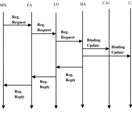
When the MN had registered to the HA with its new temporary CoA after moving to a foreign network, the HA keep its CoA in its cache. Thereafter, HA will forward this binding update information to all the CAs in its network. The CAs also stores the binding between the permanent IP address of the MN and temporary CoA, in its binding cache and starts a timer. When this timer runs out, that BU got expire and the CA either remove that BU from its cache or send a request to the HA for new update if cache is available. This passing of the binding information from HA to CAs is shown in figure 2. Thus every time whenever the HA receive any update from MN, it will forward this binding update to CAs such that the movement of MN is transparent to these agents and can provide optimized paths to the intended destination.
Fig 2: Registration Phase.
Phase 3: Route Optimization Phase
Now whenever any Correspondent node (CN) wants to send data to MN, it will send it to the home address of the MN towards the home network as it is not aware about the current location of the MN. When the data packet enters the home network, it enters through CA as it is present at the edge of the network. The CA after determining the destination of the packet, go through its binding cache to check the current location of the MN. Thereafter knowing the location, the CA forwards the data packet directly towards the MN, thus optimizing the path. Hence the triangle routing problem is avoided. However, this is more efficient as compared to [7], as even in the beginning phase there is no need to send the data to HA. If the CA initially does not have the current location of the MN, it had to forward the data towards HA, which afterwards tunnel the data towards the MN. Thus the data had to follow a long path with a number of intermediary nodes to the HA, resulting into a significant delay which can reduce the performance of the whole network. Hence reducing the delay and improving the performance of the network. Figure 3 illustrates the route optimization phase.
During this phase if the MN moves to a new FA under the same LG, the route optimization will not be interrupted and
work as the same before this inter-domain movement as the CoA for the MN remain the same gateway (LG).
Fig 3: Forwarding the data from CN to MN with optimized route.
Phase 4: Re - Optimization Phase
There may be probability of MN to move to a new domain under new gateway (LG). In such a case the MN is required to register its new CoA with its HA, such that the HA is aware of the movement of the MN.
Fig 4: Re-optimization phase.
After receiving the binding update from MN, HA will update its cache and simultaneously forwards the same to the CAs of its network, hence making them aware of the movement of the MN.The CAs thereafter updates their binding cache with new CoA of the MN and establishes a new LSP accordingly. Figure 4 shows the re-route optimization phase.
Next when the CA receives a packet destined towards the MN, it will check its binding cache and forwards the packet
FA
Reg. Reply Reg.
Reply Reg.
Reply Binding
Update Reg. request
Reg. request
Reg. request
CN CA1 HA New LG MN
Update Binding Cache Reg.
Reply
Reg. Reply
Reg. Reply
Binding Update Binding
Update Reg.
Request Reg.
Request Reg.
Request FA
MN LG HA CA1
LG CA
Data to MN
Data to MN Data to
MN Data to
MN
MN
CN HA FA
Check Binding Cache , CoA = MN
towards the new location of the MN with new CoA as new LG.
4.
SIMULATION ANALYSIS
In this section the performance of the proposed scheme with hand-off has been evaluated and compared with the optimization scheme in [7]. We implemented it on the Network Simulator 2 (NS-2). The topology used for evaluation comprised of 11 nodes as shown in figure 5. The various nodes are MN as mobile node, HA as home agent, CN as correspondent node, CA as the correspondent agent, LG as gateway, FA1 and FA2 as foreign agents and LSR as intermediate routers.
During the simulation, MN will be moving from HA to FA1 and then to FA2. Thus, node mobility causes the MN to change its point of connection to the network. CN will be communicating with MN at a constant bit rate.
Figure 6 and figure 7 shows the sending as well as the receiving times of each packet for our scheme and [7] respectively. The x-axis represents the time in seconds and the y-axis represents the packet sequence number. As shown in the graph the upper line represents the packets sent by the CN and the lower line shows the packets received at the MN. It can be observed from the graph that when the MN is under FA1 and when under FA2. Also, points A and B in the graph show the handover points from one FA to another.
Fig 5: Simulation Topology
For both the schemes, the sending and receiving time for the packets in the beginning phase i.e. when MN is under HA is same. The difference comes when MN moves away from HA. In figure 6, the sending and receiving time for each packet is almost same (i.e. small delay). Also the gap A and B is smaller due to the buffering technique used in handover. Hence number of lost packets is also less. However in figure 7, the sending and receiving time for each packet when MN has moved away from HA is significant, thus introducing delay and degrades the performance of the system. Also the gap A and B are large which signifies more number of packets lost during handover.
Fig 6: Packets sent and received for proposed optimization with hand-off.
Fig 7: Packets sent and received for route optimization without hand-off.
Fig 8. Packet Loss rate in both the schemes.
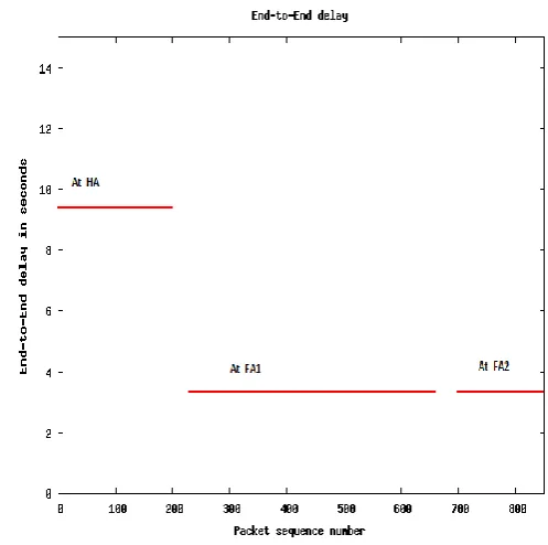
Fig 9: End-to-end delay for proposed route optimization with hand-off.
Figure 9 and 10 illustrates the end-to-end delay for each packet sent towards the MN, when MN is at HA and MN is at FA1. It can be observed that when MN is at HA, the delay for both the schemes is almost same. However when MN moves to FA1, the delay for proposed scheme with hand-off is comparatively less to that of [7].
For proposed route optimization, end-to-end delay is approximately 1.8 seconds whereas for optimization without hand-off the value is 3.9 seconds.
Fig 10: End-to-end delay for proposed route optimization without hand-off.
The reason for above difference in delay is due to the fact that the CA already has the information about the current location of MN. Also the packet loss rate has been reduced considerably by employing hand-off technique.
5.
CONCLUSION
To reduce the total end-to-end delay and lower the packet loss rate, we proposed a scheme which employs route optimization using Correspondent Agents (CA). These CAs stores the updates of MN received from HA whenever the MN changes its location and moves to a new domain. Thus even during the beginning phase there is no need to send the packets to HA. Also the packet loss rate due movement of MN has been reduced by employing a hand-off technique in which FA buffers the packets and forwards the buffered packets to the new FA when receives a notification of successful registration with new FA. Hence the number of lost packets during handover has been reduced considerably. Thus we can conclude that our proposed route optimization technique with hand-off has improved the overall performance of the system ensuring high QoS
.
6.
REFRENCES
[1] Tingzhou Yang, Yixin Dong, Bin Zhoy Dimitrios Makrakis, (2002) “Profile Based Mobile MPLS Protocol”, IEEE CCECE 2002 Canadian Conference On Electrical And Computer Engineering, Vol 3, pp 1352-6.
[2] Shengling Wang, Yong Cui, Sajal Das, Mingwei Xu,(2008) “Optimized Mobile MPLS” , 2008 IEEE International Conference on Communications Workshops, pp 441-5.
[3] E. Rosan , A. Viswanathan and R. Callon (2001) “Multiprotocol Label Switching Architecture” , RFC 3031.
2006 International Conference on Wireless Communications, Networking and Mobile Computing, Vol. 2, pp 104-7.
[5] Prawit Chumchu, Somphol Sirisaingkarn, Thawatchai Mayteevarunyou, (2011), “Performance Analysis and Improvement of Mobile MPLS”, 2011 International Conference on Information Networking (ICOIN), pp 317-22.
[6] Wisitsak Sa-Ngiamsak, Piyaporn Krachodnok, (2006) “Recovery Scheme For Qos Guaranteed Mobile Ip Over Mpls Network”, 2006 1st International Symposium on Wireless Pervasive Computing, pp 1-5.
[7] Savinya Polvichai and Prawit chumchu, (2011) “MOBILE MPLS with Route Optimization: The proposed protocol and simulation study ”, 2011 Eighth International Joint Conference on Computer Science and Software Engineering (JCSSE), pp 34-39.
[8] Azimeh Safidcon, Ferhat Khhendek,(2007) “Integration of MIP ROQS Optimal Path Selection and MPLS”, 2007 ISCIT '07. International Symposium on Communications and Information Technologies, pp 643-8.
[9] Abd-Elhamid M. Taha, Hossam Hassanein and Hussein T. Moutfah, (2004) “Integrated Solutions For Wireless MPLS And Mobile IP: Current Status and Future Directions”, 2004. Canadian Conference on Electrical and Computer Engineering, Vol. 3, pp 1463-66.
![Figure 6 and figure 7 shows the sending as well as the receiving times of each packet for our scheme and [7] respectively](https://thumb-us.123doks.com/thumbv2/123dok_us/1329586.1641202/5.595.313.563.87.358/figure-figure-shows-sending-receiving-packet-scheme-respectively.webp)