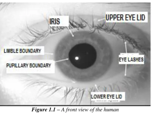
various high risk sectors like aviation, border patrol and defence. The banking and financial sector has to adoptthis system because of its robustness and the advantages it provides in cutting costs and making processes more streamlined. The technology started out as a novelty however due exigencies in the banking sector characterized by decreasing profits it became a necessity. The use of Biometric ATM’s based on iris recognition technology has gone a long way in improving customer service by providing a safe and paperless banking environment. A biometric system provides automatic recognition of an individual based on some sort of unique feature or characteristic possessed by the individual. Biometrics gained lot of attention over recent years as a way to identify individuals. As technology and services have developed in the modern world, human activities and transactions have proliferated in which rapid and reliable personal identification is required. The developments in science and technology have made it possible to use biometrics in applications where it is required to establish or confirm the identity of individuals.The use of biometric indicia for identification purposes requires that a particular biometric factor be unique for each individual that it can be readily measured, and that it is invariant over time. Human iris on the other hand as an internal organ of the eye and as well protected from the external environment, yet it is easily visible from within one meter of distance makes it a perfect biometric for an identification system with the ease of speed, reliability and automation. The iris is a thin circular diaphragm, which lies between the cornea and the lens of the human eye. The iris is perforated close to its centre by a circular aperture known as the pupil. The function of the iris is to control the amount of light entering through the pupil, and this is done by the sphincter and the dilator muscles, which adjust the size of the pupil. The iris recognition systems have recently shown very high accuracies in verifying an individual’s identity. A complete iris recognition system can be split into four stages: Image acquisition, segmentation, encoding and matching. The results of this system are very efficient for ATM transactions.
Keywords—Biometrics,IRIS, ATM, Segmentation, Feature extraction, IRIS localization,Normalization.
I.
INTRODUCTION
The false acceptance rate for iris recognition systems is 1 in 1.2 million, statistically better than the average fingerprint recognition system. The real benefit is in the false-rejection rate, a measure of authenticated users who are rejected. Fingerprint scanners have a 3 percent false-rejection rate, whereas iris scanning systems boast rates at the 0 percent level.A highly accurate technology such as iris-scan has vast appeal because the inherent argument for any biometric is, of course, increased security.
II.
BENEFITS
OF
USING
IRIS
TECHNOLOGY
The iris is a thin membrane on the interior of the eyeball. Iris patterns are extremely complex.Patterns are individual (even in fraternal or identical twins).Patterns are formed by six months after birth, stable after a year. They remain the same for life.Imitation is almost impossible.Patterns are easy to capture and encode. Biometrics is the automated recognition of individuals based on behavioural and biological characteristics. The technology is designed to automatically take a picture from person and match it to the digitized image stored in the biometric passport. In the field of financial services, biometric technology has shown a great potential in offering more comfort to customers while increasing their security. Applications due to information protection issues, it is believed that the technology will find its way to be widely used in many different applications. Biometrics such as signatures, photographs, fingerprints, voiceprints, DNA and retinal blood vessel patterns all have significant drawbacks. Face Recognition: Changes with Age, Expression, Viewing angle, Illumination. Finger Print Recognition: Fingerprints or handprints require physical contact, and they also can be counterfeited and marred by artifacts. IRIS recognition is one among the biometric systems the tool used for this recognition is MATLAB. To determine the uniqueness of iris patterns in terms of hamming distance distribution by comparing template generated from different eyes. The iris consists of a number of layers the lowest is the epithelium layer, which contains dense pigmentation cells. The stromal layer lies above the epithelium layer, and contains blood vessels, pigment cells and the two iris muscles. The density of stromal pigmentation determines. The color of the iris. The externally visible surface of the multi-layered iris contains two zones, which often differ in color. An outer ciliary zone and an inner pupillary zone, and these two zones are divided by the collarets which appears as a zigzag pattern.
2.1Success rate:Failure rate using IRIS technology in just 1 in 1.2 million. When compared to other technology systems this was found as very efficient. Hence we have chosen this technology.
III.
ARCHITECTURE
OF
IRIS
RECOGNITION
A complete iris recognition system can be split into four stages: Image acquisition, segmentation, encoding and matching. The data acquisition step captures the iris images. Infra-red illumination is used in most iris image acquisition. The iris segmentation step localizes the iris region in the image. For most algorithms, and assuming near-frontal presentation of the pupil, the iris boundaries are modelled as two circles, which are not necessarily concentric. The inner circle is the papillary boundary (between the pupil and the iris). The outer circle is the limbic boundary (between the iris and the sclera). The noise processing is often included in the segmentation stage. The encoding stage encodes the iris image texture into a bit vector code. In most algorithms, filters are utilized to obtain information about the iris texture. Then the outputs of the filters are encoded into a bit vector code. The corresponding matching stage calculates the distance between iris codes, and decides whether it is an authorized match or unauthorized match.
3.1 Enrollment: The enrollment phase creates a user profile for subsequent authentication activities.Typically, a new user provides multiple biometric reading samples that are combined to form one stored record.
Fig3.1 Architecture of iris recognition system
3.3 Image acquisition: One of the major challenges of automated iris recognition is to capture a high-quality image of the iris while remaining non-invasive to the human operator.
3.4 Image Segmentation: At this stage, the iris is extracted from the eye image. The extracted iris region was then normalized into a rectangular block with constant dimensions to account for imaging inconsistencies. The integro-differential operator for locating the circular iris and pupil regions, and also the arcs of the upper and lower eye lids. The integro-differential operator is defined as 𝑚𝑎𝑥(𝑟,𝑥𝑝 ,𝑦𝑜) 𝐺𝜎∗
𝑑 𝑑𝑥
𝐼(𝑥 ,𝑦 ) 2𝜋𝑟 (𝑟,𝑥0,𝑦𝑜) 𝑑𝑠
Where I(x,y) is the eye image, r is the radius to search for, Gs(r) is a Gaussian smoothing function, and s is the contour of the circle given by r, xo, yo, The operator searches for the circular path where there is maximum change in pixel values, by varying the radius and centre x and y position of the circular contour. The operator is applied iteratively with the amount of smoothing progressively reduced in order to attain precise localization. Eyelids are localized in a similar manner, with the path of contour integration changed from circular to an arc. The segmented iris image is normalized and converted from Cartesian image coordinates to polar image coordinates.
3.5 Feature Extraction: The iris contains important unique features, such as stripes, freckles, coronas, etc. These features are collectively referred to as the texture of the iris. The 2D version of Gabor filters in order to encode iris pattern data. A 2D Gabor filter over the an image domain (x, y) is represented as
G x, y = e−π[
x −x 0 2 σ2 + y −y 0 2β2 ]
e−2π[u0 x−x0 +v0 y−y0 ]
Where (x0, y0) specify position in the image, (α, β) specify the effective width and length,and (u0,v0) specify modulation, which has spatial frequency the odd symmetric and even symmetric 2D Gabor filters are shownin figure.
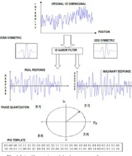
Daugmandemodulates the output of the Gabor filters in order to compress the data. This is done by quantizing the phase information into four levels, for each possible quadrant in the complex plane.
Figure 3.2 a quadrature pair of 2D Gabor filters
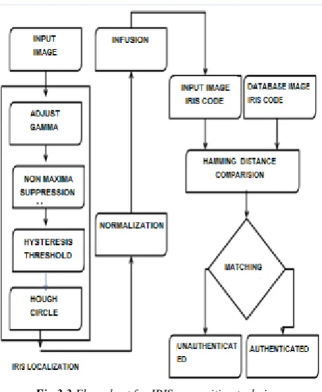
Fig 3.3 Flow chart for IRIS recognition technique
3.7 Hamming Distance: Hamming distance was originally conceived for detection and correction of errors in digital communication. It is simply defined as the number of bits that are different between two bit vectors.
HD =1
N Xj(XOR)Yj
N
j=1
IV.
PROPOSED IRIS RECOGNITION ALGORITHM
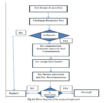
Fig 4.1 Block diagram of the proposed approach
4.1 Eye image acquisition:An important and complex step of iris recognition system is image acquisition. Especially for Indians, the iris is small in size and dark in color. It is difficult to acquire clear images.
4.2 Challenge-response test: Biometric features may be counterfeited and criminally used. This is a crucial weakness of the biometric system. This module aims to ensure that an input image actually originates from a person instead of iris photographs, phony eyes, or other artificial sources.
This method verifies the response of the pupil diameter by varying illumination levels at the same distance from the eye. The algorithm of this method is elaborated as follows:
Step 1: Capture the same person’s eye images under different lighting levels
Step 2: Measure the pupil diameter from the captured eye images. If these values are divergent then the image is actually from a real source (human), otherwise artificial sources may have been used. The diameter of the pupil is calculated by satisfying (1). Equations (2) and (3) describe the challenge-response process.
If current pixel value is greater than two threshold levels means that current pixel & 8 neighbour pixels also marked as edges. If that current pixel value is greater than only one threshold means that current pixel only marked as an edge.
5.4 Hough Transform: The Hough transform is a standard computer vision algorithm can be used to determine the parameters of simple geometric objects, such as lines and circles, present in an image. The circular Hough transform can be employed to deduce the radius and centre coordinates of the pupil and iris regions. From the edge map, votes are cast in Hough space for the parameters of circles passing through each edge point. These parameters are the centre coordinates xc and yc, and the radius r, which are able to define any circle according to the equation.
𝑥𝑐2+ 𝑦𝑐2− 𝑟2= 0
A maximum point in the Hough space will correspond to the radius and centre coordinates of the circle best defined by the edge points. Wildes and Kong also make use of the parabolic Hough transform to detect the eyelids, approximating the upper and lower eyelids with parabolic arcs, which are represented as.
(−(𝑥 − ℎ𝑗) sin 𝜃𝑗+ (𝑦 − 𝑘𝑗) cos 𝜃𝑗)2= 𝑎𝑗( 𝑥 − ℎ𝑗 cos 𝜃𝑗+ 𝑦 − 𝑘𝑗 𝑠𝑖𝑛 𝜃𝑗)
Where aj controls the curvature, (hj,kj) is the peak of the parabola and θjis the angle of rotation relative to the x-axis. In performing the preceding edge detection step, Wilds et al. bias the derivatives in the horizontal direction for detecting the eyelids, and in the vertical direction for detecting the outer circular boundary of the iris
5.5 Iris Image Normalization: As the iris is captured under different conditions like non-uniform illumination, eye blink, pupil radius change due to varying lighting etc., it is possible for the output ofiris images to be in different sizes. These variations may affect the results of iris matching. To overcome this issue, iris image has been converted to standard size with width and height as 360 and 48 pixels respectively. Iris dilation or erosion process is also carried out to extend or squeeze iris strip size when fewer/higher amounts of data are obtained in the iris portion. This process is called iris normalization.process ofradial scan module.
x = _ xc + ri cos ((ð/180) è), y = _ yc + risin((ð/180)è) (6)
5.6 Canny edge detection: Edges characterize boundaries and are therefore a problem of fundamental importance in image processing. Edges in images are areas with strong intensity contrasts a jump in intensity from one pixel to the next. Edge detecting an image significantly reduces the amount of data and filters out useless information, while preserving the important structural properties in an image. The Canny edge detection algorithm is known to many as the optimal edge detector.
5.7 Iris Image Enrichment: Image enrichment process is based on spatial domain approach. The original iris image has low contrast and may have non-uniform illumination caused due to the irregular position of the light source. These problems may affect subsequent feature extraction and iris matching process. In order to obtain a well-distributed texture image, the iris image is enriched using local histogram equalization. Figure 10a shows the effect of applying histogram equalization process.
VI.
FEATURE ENCODING
The final process is the generation of the iris code. For this, the most discriminating feature in the iris pattern is extracted. The resulting phasor lies using the wavelet.
H Re ,Im sgn Re ,Im I ρ, ∅
ρ,∅
e−iωθ0−∅ . e − r 0−ρ 2
α2 e − θ0−∅ 2
β2 ρdρd∅
Where, h Re ,Im has the real and imaginary part, each having the value 1 or 0, depending on which quadrant it lies in.The
frequency response of a Log-Gabor filter is given as.
(f)= exp −(log (
𝑓 𝑓0))
2
Fig 6.1 An illustration of the feature encoding process.
6.1 Performance Evaluation: The performance evaluation of proposed method was measured by the two error rates such as FRR (False Rejection Rate) and FAR (False Acceptance Rate). The FAR and FRR was computed as
FAR % No of false acceptances Total no of imposter attempts
FRR % No of false rejection Total no of authentic attemptes
VII.
CONCLUSION
Finally, in this section gives features of the iris implementation encoded by convolving the normalised iris region with 1D Log-Gabor filters and phase quantising the output in order to produce a bit-wise biometric template. The Hamming distance was chosen as a matching metric. The experimental results show that the proposed approach has a faster operation and good recognition performance. All experimental results have demonstrated that the proposed algorithm has anencouraging performance. This also confirms that effective iris segmentation is important for an iris recognition system. However, efforts remain to be taken to further improve its performance. In order to improve the automatic segmentation algorithm, a more elaborate eyelid and eyelash detection system could be implemented.
Thus the above method can be efficiently implemented for the ATM transactions
REFERENCES
[1]. J. Daugman. High confidence visual recognition of persons by a test of statistica independence. IEEE Trans.PAMI, 15(11):1148–1161, November 1993.
[2]. J. Daugman. The importance of being random: Statistical principles of iris recognition. Pattern Recognition, 36(2):279–291, 2003.
[3]. J. Daugman. Anatomy and physiology of the iris. [htlm-doc.], [retrieved 15.10.2003]. From: http://www.cl.cam.ac.uk/users/jgd1000/anatomy.html. [4] R.Wildes. Iris recognition: An emerging biometric technology. Proceedings of the IEEE, 85(9):1348–1363, September 1997.
[4]. W. Boles and B. Boashash. A human identification technique using images of the iris and wavelet transform. IEEE Trans. Signal Processing, 46(4):1185 1188, April 1998.
[5]. S. Lim, K. Lee, O. Byeon, and T. Kim. Efficient iris recognition through improvement of feature vector and classifier. ETRI Journal, 23(2):61–70, 2001.
[6]. S. Noh, K. Pae, C. Lee, and J. Kim. Multiresolution independent component analysis for iris identification. In Proceedings of ITC-CSCC’02, pages 1674-1678, 2002.