Abstract— Wire electrical discharge turning (WEDT) allows
success in the machining of advanced materials, particularly for the cylindrical shape components used in the metrology, medical and aerospace field. Using WEDT technology, the micro dimension of geometrical features can be machined without constraints on difficult-to-machine electrically conductive materials. The high precision with large aspect ratio machining capability make WEDT valuable. The correct machining parameter selection is the most important aspect to take into consideration when machining by WEDT. Therefore, the purpose of this study was to rank, determine and optimise the machining parameters that affect the material removal rate (MRR) in WEDT process. As WEDT has as much as eleven control parameters in this study, representing a large number of machining, the Taguchi L-12 orthogonal array was used to obtain the required data with a minimum number of experiments. By using similar experimental data, the regression equation was developed to represent as fitness function for optimisation by genetic algorithm (GA). It was found that by selecting the fast feed of workpiece to machining zone, the faster material was removed and moreover, it dominated other machining parameters. The optimised parameters yield 1.398 mm³/min as the maximum value predicted for MRR recommended by GA.
Index Term— Genetic Algorithm, Micro-cylindrical Machining, MRR, Taguchi, WEDT
I. INTRODUCTION
Technology of machining with wire electrical discharge turning (WEDT) provides a satisfactory alternative to the conventional turning process, especially for the machining of high strength and brittle materials in applications of complex shapes and high precision part components as it does not possess any mechanical force during machining and it is not restricted by material properties. In principle, the WEDT is similar to the conventional wire electrical discharge machining (WEDM) as WEDT utilises the same principle of electrode wire travelling to erode the workpiece. However, in WEDT, the cylindrical workpiece is situated in a rotating manner as compared to the WEDM, whose workpiece is stationary.
Nowadays, the potential capability of WEDT has extended to the fabrication of micro cylindrical parts. Some researchers
have contributed to the fabrication of micro cylindrical parts by WEDT such as the high aspect ratio of micro-pin [1], [2] and high accuracy of micro-cutting tool with complex geometries [3]. The machining performance of WEDT is defined and influenced by its machining parameters, which significantly affects the outcome of the process. Giridharan and Samuel [4] investigated the machining parameters such as the pulse-off time, servo feed as well as the spindle speed rotation to the discharge energy and modelled it to predict the material removal rate (MRR) and surface roughness. The models proposed by them are significantly reliable because the generated discharge energy was directly produced from the energy conversion of WEDT. Srivastava et al. [5] studied the effects of rotational spindle speed in WEDT towards surface integrity and the MRR while machining aluminium-based metal matrix composite. They found that the MRR and surface roughness reduced when the spindle speed increased and that the machined surface looked dull and contained the small craters.
According to literature, the most important performance measures in WEDT is the MRR, where it specifies the economics of machining and rate of production. Although the WEDT process can potentially machine down to micro dimensions, the machining characteristics and the rate of production have not been comprehensively recognised until today. In practice, it is very challenging to obtain the ideal performance of machines owing to the fact that there are too many controllable machining parameters [6], [7]. Some of the machines possess supplementary modes and controllers to regulate the machining conditions such as reverse polarity, arcing controller, rough-cut mode and finishing mode [8]– [10].
With the plethora of machining parameters and great differences in each machine, it is even more challenging to study the effects of machining parameters by conventional single-factor experiments. Numerous number of experiments are required, which will consume a lot of time at high costs. In addition, the pulse characteristics in WEDT are greatly different from WEDM machines due to the rotating of the workpiece; which can result in more frequent occurrences of
Experimental Analysis on Parameters Affecting
the Material Removal Rate in Wire Electrical
Discharge Turning using the Taguchi Method
R. Izamshah
1,2, M. Akmal
2*, M.S. Kasim
1,2, S.B. Mohamed
31Precision Machining Group, Advanced Manufacturing Centre,Universiti Teknikal Malaysia Melaka, Hang
Tuah Jaya, 76100 Durian Tunggal, Melaka, Malaysia.
2
Department of Manufacturing Process, Faculty of Manufacturing Engineering, Universiti Teknikal Malaysia Melaka, Hang Tuah Jaya, 76100 Durian Tunggal, Melaka, Malaysia.
3Department of Manufacturing Technology, Faculty of Innovative Design and Technology, Universiti Sultan
arc pulses and arc regions - leading to the reduction in the MRR [11].
Due to this, a simple but reliable method based on a statistical approach was employed in the experiments to acquire information regarding the effects of various machining parameters on the MRR with a minimum number of experiments. To the authors’ best knowledge, there are no published works studying the effects of machining parameters on the MRR statistically in the fabrication of micro cylindrical shape components by WEDT.
In this paper, a planned set of experiments was carried-out using the Taguchi L-12 orthogonal array and the effects of the machining parameters on the MRR was analysed. Afterwards, the machining parameters were optimised by using genetic algorithm (GA) approach. Titanium alloy was chosen as the workpiece material in this study due to its growing range of applications on micro-devices in the medical and metrology field. The topography of the machined surface was also analysed by scanning electron microscopy (SEM).
II. METHODOLOGY
A. Experimental Setup
The machining trials were carried out on a Mitsubishi Ra90 WEDM machine with assistance from the precise spindle unit in order to perform the micro-turning process as illustrated in Fig. 1. The de-ionised high pressurised water jets were applied to the machining zone to flush the debris away.
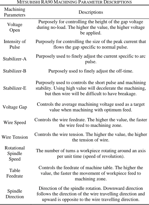
This WEDM machine has special features in which it is capable to control the degree of arc pulses and short pulses also known as stabilisers by machine manufacturers. In order to determine the effects of parameters in WEDT, all control machining parameters were investigated in this research study because the formation of arc and its regions highly occurred in WEDT as compared to WEDM, which altered the fundamental of spark erosion nature. Table I and Fig. 2 shows the details of the parameters and its function to the WEDT machining process.
The experimental setup was as follows: pure brass of 0.25 mm diameter is employed as wire electrode, titanium alloy grade 5 (Ti6-Al-4V, chemical composition percentage by weight, Aluminium= 6.9%, Vanadium= 4.1%, Carbon= 0.10%, Iron= 0.30%, Silicon= 0.15%, Oxygen= 0.20%, Nitrogen= 0.05%, Hydrogen= 0.015%, balance Titanium) with tensile strength of 1000 MPa and hardness of 36 HRC was chosen as the workpiece material. This kind of alloys is known to be challenging when processed by conventional machining [12]. The initial workpiece dimensions were 20 mm of length and 9.49 mm in diameter. The MRR of machined workpiece was taken as the response variable and calculated by obtaining the differences in the diameter of each workpiece before and after per unit machining time by using the Meiji Zoom stereo microscope as indicated in (1). R denotes the initial radius of the workpiece [mm], r denotes the final radius of the workpiece after machining [mm], l denotes the machining length [mm] and t denotes the machining time [min].
(1)
Fig. 1. WEDT Experimental setup TABLEI
MITSUBISHI RA90MACHINING PARAMETER DESCRIPTIONS
Machining
Parameters Descriptions Voltage
Open
Purposely for controlling the height of the gap voltage during no-load. The higher the value, the higher voltage
be applied. Intensity of
Pulse
Purposely for controlling the size of the peak current that flows the gap specific to normal pulse. Stabilizer-A Purposely used to finely adjust the current specific to arc
pulse.
Stabilizer-B Purposely used to finely adjust the off-time. Stabilizer-E
Purposely used to controls the short pulse and machining stability. Using high value will decelerate the machining,
but then wire will be difficult to have breakage. Voltage Gap Controls the average machining voltage used as a target
value when machining with optimum feed. Wire Speed Controls the wire feedrate. The higher the value, the faster the wire feed to machining zone. Wire Tension Controls the wire tension. The higher the value, the higher
the tension of wire. Rotational
Spindle Speed
The number of turns a workpiece rotating around an axis per unit time (speed of revolution).
Table Feedrate
Controls the feedrate of machine table. The higher the value, the faster the movement of workpiece feed to
machining zone. Spindle
Direction
Direction of the spindle rotation. Downward direction follows the direction of the wire travelling direction and
Fig. 2. Mitsubishi Ra90 theoretical pulse characteristics
B. Taguchi Orthogonal Array
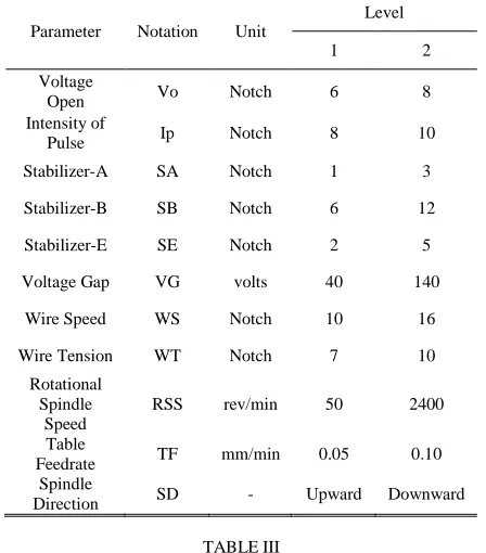
In this present study, the behaviour of eleven machining parameters was evaluated and ranked according to the L-12 Taguchi orthogonal array design procedure by using the Minitab 16 statistical software. Each of the machining parameters consisted of two levels, which were level 1 and level 2 as indicated in Table II. Level 1 represented the minimum value while level 2 represented the maximum value of respective parameters. The Taguchi method offered simplicity in conducting an experiment with a large number of factors by conducting fewer experimental trials [13].
The application of the Taguchi method has been widely used by a great number of researchers since it became a reliable tool to diagnose the machining parameters that renders the quality of the products or processes while minimising the variations caused by external noise. In selection of the orthogonal array design for this method, selection depended on the number of parameters, interactions and their level.
Taguchi uses signal-to-noise (S/N) ratio to assess the quality the of the respective parameter. The term “signal” here refers to the desirable value and “noise” refers to the undesirable value. The aim of using S/N ratio as a measure of effectiveness was to develop products or processes that were insensitive to noise factors [14]. The S/N ratio indicated the degree of the predictable quality of a product or process in the occurrence of noise factors.
Machining parameters with a high S/N ratio always yields the optimum quality with less amount of variance. Taguchi categorised response characteristics into three special types, which included the larger-the-better, the smaller-the-better and the nominal-the-better [15].
The larger-the-better here refers to the responses of ideal quality of the products or processes as intended to be maximum. The smaller-the-better refers to the responses of ideal quality of the products or processes as intended to be minimum. The nominal-the-better refers to the responses of ideal quality of the products or processes equated with a particular nominal value.
In this study, the larger-the-better was considered to maximise the MRR, and the S/N ratio was expressed in (2). η represents the S/N ratio, yi represents the response value of the
ith experiment, while n is the number of replications of each trials [16].
[
∑
(
)
]
(2)
Table III shows the design matrix of the L-12 Taguchi orthogonal array. L-12 design allows the evaluation of machining parameters on main effects only. Therefore, the interaction effect of machining parameters was assumed as negligible in this study. The trials were conducted randomly with three replications in order to attain the validity and accuracy of the experiment.TABLEII
MACHINING PARAMETERS AND THEIR NOTATION,UNIT AND LEVELS
Parameter Notation Unit
Level 1 2 Voltage
Open Vo Notch 6 8 Intensity of
Pulse Ip Notch 8 10 Stabilizer-A SA Notch 1 3 Stabilizer-B SB Notch 6 12 Stabilizer-E SE Notch 2 5 Voltage Gap VG volts 40 140
Wire Speed WS Notch 10 16 Wire Tension WT Notch 7 10
Rotational Spindle
Speed
RSS rev/min 50 2400 Table
Feedrate TF mm/min 0.05 0.10 Spindle
Direction SD - Upward Downward TABLEIII
EXPERIMENTAL DESIGN MATRIX USING L-12ORTHOGONAL ARRAY
III. RESULTS AND DISCUSSION
In general, the MRR result obtained is relatively high before an optimization as indicated in Table IV but it is still behind compared to macro sized machining by WEDT [17], [18]. Only slow feedrate can be applied in this study due to the volume of material being removed is about 30% more than machining macro sized of workpiece by WEDT [5], [11]. Large radial depth of cut used for obtaining final micro sized parts has restricted the feeding motion. Followings are the result in satisfying the research proposed objective.
A. Ranked of Parameter
A higher MRR is an indication of better productivity in WEDT process. The results of the MRR for each of the experiments based on orthogonal array and its corresponding S/N ratio are listed in Table IV.
The most important principle in the Taguchi method to evaluate the collected data is the S/N ratio. In this study, the S/N ratio should have a maximum value in order to obtain optimum process parameters. The response table (Table V) showed the average of each response characteristic for each level of the respective factors. This table tabulated the ranks among the process parameters that contributed to the MRR based on delta statistics. Delta statistics calculated the relative magnitude of efforts among the process parameters by minusing the lowest average from the highest average of each factor [19].
Therefore, the Minitab 16 software appointed ranks based on delta values; rank 1 to highest delta value, rank 2 to the second highest and, so on. The ranks represent the importance of each parameter to the MRR. The ranks and delta values showed that table feedrate had the greatest effect on the MRR, followed by pulse intensity, spindle direction, wire tension, voltage gap, stabilizer-E, stabilizer-A, stabilizer-B, rotational spindle speed, wire speed, voltage open.
TABLEIV
EXPERIMENTAL RESULT AND THEIR S/NRATIO Trials Material Removal Rate (mm³/min)
Signal to Noise Ratio MRR 1 MRR 2 MRR 3 Mean
1 0.711 0.704 0.711 0.709 -2.992 2 0.657 0.662 0.671 0.663 -3.569 3 1.366 1.371 1.374 1.370 2.736 4 0.676 0.674 0.679 0.677 -3.394 5 0.651 0.656 0.652 0.653 -3.704 6 1.272 1.298 1.334 1.301 2.284 7 1.326 1.321 1.324 1.324 2.435 8 1.296 1.308 1.310 1.305 2.310 9 0.674 0.674 0.679 0.676 -3.403 10 1.367 1.371 1.362 1.367 2.713 11 0.671 0.682 0.675 0.676 -3.403
12 1.337 1.349 1.355 1.347 2.588 TABLEV
RESPONSE TABLE FOR S/NRATIOS OF MRR Parameter\Level 1 2 Delta Rank
Voltage Open -0.4601 -0.4398 0.0203 11 Intensity of Pulse -0.5562 -0.3437 0.2125 2 Stabilizer-A -0.5094 -0.3906 0.1188 7 Stabilizer-B -0.4278 -0.4722 0.0445 8 Stabilizer-E -0.3886 -0.5114 0.1228 6 Voltage Gap -0.5326 -0.3674 0.1651 5 Wire Speed -0.4389 -0.4611 0.0222 10 Wire Tension -0.3674 -0.5326 0.1652 4 Rotational Spindle
Speed -0.4362 -0.4637 0.0275 9 Table Feedrate -3.4110 2.5110 5.9220 1 Spindle Direction -0.3660 -0.5340 0.1681 3
B. Parametric Influences and Analysis
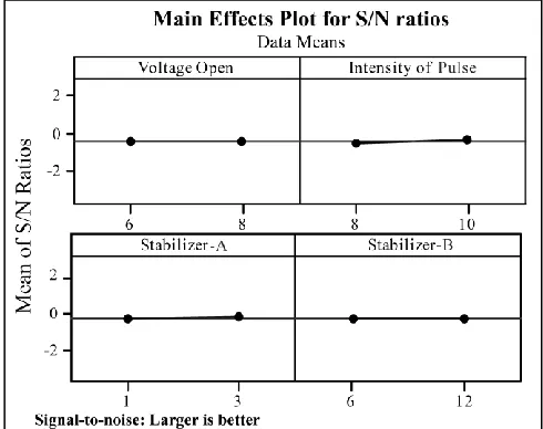
The S/N ratio plots show all the effects of eleven process parameters toward the MRR in WEDT (Fig. 3, Fig. 4, and Fig. 5). In spark erosion machining, the pulse waveform played an important role in producing ideal plasma channels in removing the material. In this study, all the electrical parameters contributed to the creation of pulse characteristics as indicated in Fig. 2. Among the electrical parameters in this research study, pulse intensity dominated the other electrical parameters. By employing a high value of pulse intensity, it increased the discharge energy (Table V and Fig. 3). This increased the size of the discharge crater in terms of its depth and diameter, raised the MRR. In addition, voltage was also an important parameter to the pulse characteristics. In this study, there were two types of voltage, namely voltage open and voltage gap. Voltage open referred to the initial voltage applied during machining before the flows of amperage of current, while voltage gap referred to the average of voltage reduction after the flows of current. Astoundingly, voltage gap highly influenced the MRR rather than voltage open. One of the plausible reasons for this phenomenon may be related to the numerous occurrences of arc pulses and short pulses in WEDT as reported by Rees et al. [20] and Janardhan and Samuel [11]. According to Oßwald et al. [21], the arcing pulse occurs when the applied voltage does not rise above the average voltage gap. Therefore, the high value of applied voltage by parameter voltage open is inoperative as long as the arc pulse predominates the pulse characteristics during the machining. By applying a high value of voltage, the voltage open or voltage gap will increase the MRR.
pulses, subsequently reducing the number of ideal plasma channels produced by normal pulses that had the capability to sufficiently remove the material. For stabilizer-A, the MRR increased by increasing the notch value from 1 to 3 (Fig. 3). Stabilizer-A was specified as the switch to finely adjust the current to control arc pulse. The occurrences of arc pulse in WEDT was quite frequent as compared to the conventional WEDM [11]. Thus, by increasing the notch value from 1 to 3 for stabilizer-A, this allowed the large amperage of current with arc pulse to erode the large volume workpiece materials. Knowingly, the arc pulse had adequate energy in generating sufficient plasma channel to erode the materials but was still lagging as compared to normal pulses in removing the materials [22]. All the results regarding the voltage, stabilizer-A and stabilizer-E has been reflected in the occurrences of arc and short pulses in WEDT as reported by Rees et al. [20] and Janardhan and Samuel [11]. They found that by introducing the rotating workpiece in conventional WEDM, it changed the pulse nature of spark erosion. They also found that WEDT pulses contained a lot of false discharge such as occurrences of shorts pulse, arcs pulse and arc regions.
Another interesting electrical parameter that was noteworthy for discussion in this research study was the relation of stabilizer-B to the off-time in pulse waveforms (Fig. 2). The higher the value, the more number of sparks fell off during the machining process, which resulted in less amounts of discharge occurrences and subsequently, reduced the MRR. However, the adequate amount of off-time offered the benefit of allowing the debris to be flushed away from the machining zone. Thus, this eliminated the chain-like bridge phenomenon and indirectly minimised the occurrences of short pulse.
In terms of non-electrical parameters in WEDT, table feedrate dominated the other non-electrical parameter, followed by spindle direction, wire tension, rotational spindle speed and wire speed (Table V). As shown in Fig. 5, table feedrate constituted the major effect of parameter to MRR. By increasing the table feedrate, the MRR increased. This result had similar agreements with Sun et al. [23], they indicated that the feeding speed possessed the most significant effect on the MRR in machining titanium alloy for micro cylindrical parts in WEDT. Table feedrate was certainly influenced by the MRR as the MRR was defined as the volume of material removed divided by the machining time. The calculation for the MRR used feedrate as an input value. The increase of the MRR was related to feedrate table because of the shorter machining time [24].
In addition to that, the upward spindle direction produced more MRR as compared to the downward direction. A possible explanation for this might be due to the reduction of the spark gap distance. According to Janardhan and Samuel [11], when the spark gap distance between rotating workpiece and wire electrode reduce, the ignition delay time has enough time to produce ideal plasma channel that can remove materials in excellent manner. Ignition delay time is an important time in the event of plasma channel before allowing the electrons and ions to flow through it during the discharge phase [25].
Wire tension also influenced the MRR results as the MRR slightly increased when using low tension of electrode wire.
This result may be explained by the fact that the wire vibration turned occurred under the low wire tension. As a result, the wire had a tendency to deflect and over-remove the material dimension of workpiece. These circumstances were a drawback for precision machining despite the high material being removed.
In WEDT, rotating of the workpiece changed the pulse behaviour. When the workpiece rotated at a high speed, there was a reduction in the MRR. This was because, high rotational spindle speed led to distortions of gap equilibrium [26], occurrences of variation in total number of pulse and occurrences of false discharges [20]. Therefore, poor removal mechanism by plasma channel caused less appearances of normal pulses.
For wire speed, the MRR decreased by using faster wire electrode feeding. This result was most likely caused by the occurrences of vibrating electrode wires that diminish the dynamic stability of the wire and led to unfavourable sparking conditions [27]. Moreover, by applying fast wire feeding to the machining zone, it weakened the discharge state as the removal time for debris was shortened. This caused difficulty in flushing it away, thus, destroying the machining stability with occurrences of chain-like bridge by debris that ultimately reduced the MRR.
Fig. 4. Mean of MRR S/N ratios for stabilizer-E, voltage gap, wire speed and wire tension
Fig. 5. Mean of MRR S/N ratios for spindle speed, table feedrate and spindle direction
C. Parameter Optimization
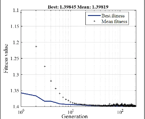
Some of the studied combination parameters has been shown to produce high MRR (Table IV). However, there are potentially other combination parameters that could yield higher MRR. In this section, the GA optimization approach was used to identify the optimum parameters in order to further improves the MRR. The problem fitness function is obtained through first-order derivative of regression analysis, as shown in (3);
MRR =
(3)
The maximization of the fitness function value of equation (3) is subjected to the boundaries of machining parameters. The range of values that present the boundaries of the optimization solution is shown as in (4). According to
equation (4), the levels and boundaries for SD has been changed to the coded value in order to allows it to be analysed by Matlab GA solver, due to the fact that it is the only categorical parameter among the other parameters. In this study, the following GA parameters options are considered: Population type = double vector (250 size); Crossover function = two point; Migration= forward (20 interval with 0.2 fraction); Mutation function= constraint dependent; Scaling function= rank; Crossover fraction= 0.8 (default)[28].
}
(4)
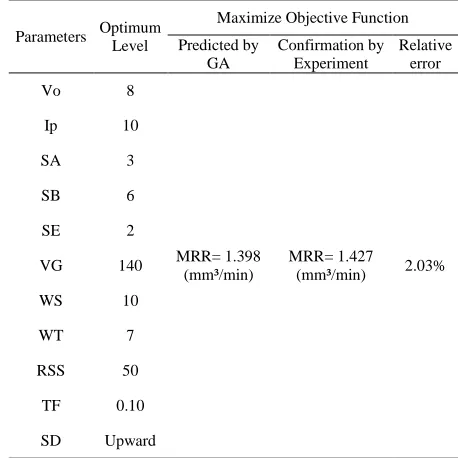
According to Fig. 6, it can be observed that the best value in maximizing MRR is 1.398 mm³/min at the end of 205 iterations and its value obtained was higher than the studied combination parameters in Table IV. Furthermore, the optimal machining parameters proposed by GA has been carried out to performed on the actual experimental with the purpose to evaluate its validity. Table VI shows the optimal machining parameters and the results of confirmation experiment. It is found that the GA proposed machining parameter produced a little high up to 1.427 mm³/min of MRR, but it is still in acceptable range as long the relative error percentage is small.
TABLE VI
THE OPTIMIZED PARAMETERS AND THE CONFIRMATION OF EXPERIMENT
Parameters Optimum Level
Maximize Objective Function Predicted by
GA
Confirmation by Experiment
Relative error Vo 8
MRR= 1.398 (mm³/min)
MRR= 1.427
(mm³/min) 2.03% Ip 10
SA 3 SB 6 SE 2 VG 140 WS 10 WT 7 RSS 50
TF 0.10 SD Upward
D. SEM Observations
During WEDT process, the discharged energy generates extreme temperatures led the materials to melted and vaporized. Every single discharge, a crater was formed on the machined surface that change the machined surface topography by effects of various process parameters. It was observed from Fig. 7 SEM micrographs of WEDT surface that it contains globules of debris, different size of craters and micro-voids. The surface topography of WEDT almost has similar figuration with surface topography of WEDM [10], but WEDT machined surface contains elongated craters because the effect of rotating workpiece makes the plasma arc column to simply slide over the machined workpiece and elongate the craters [23]. During machining, some of the molten material produced by the discharge energy was flushed away by the deionized water but the remaining molten material re-solidifies to form globules of debris as seen in Fig. 7. In this study, the occurrences of micro-void are caused by the gas bubbles expelled from the molten material during solidification due to the effects of cooling rate by de-ionized water.
Fig. 7. SEM micrographs of machined surface under optimised machining parameters; Vo= 8 notch, Ip= 10 notch, SA= 3 notch, SB= 6 notch, SE= 2 notch, VG= 140 volts, WS= 10 notch, WT= 7 notch, RSS= 50 rev/min, TF=
0.10 mm/min and SD= upward direction, MRR = 1.427 mm³/min
IV. CONCLUSION
ACKNOWLEDGEMENTS
The authors would like to thank the financial support of UTeM Zamalah Scheme as well as the facility support by the Faculty of Manufacturing Engineering, Universiti Teknikal Malaysia Melaka (UTeM). This research is also supported by Malaysia Ministry of Education for [Fundamental Research Grant Scheme (FRGS); FRGS/2/2014/TK01/UTEM/03/2].
REFERENCES
[1] Y. Zhu, T. Liang, L. Gu, and W. Zhao, “Machining of micro rotational parts with wire EDM machine,” Procedia Manuf., vol. 5, no. 1, pp. 849–856, 2016.
[2] M. Akmal, R. Izamshah, M. S. Kasim, M. Hadzley, M. Amran, and A. Ramli, “Development of a rotary axis mechanism for wire EDM turning (WEDT),” in Proc. Mech. Eng. Res. Day 2016, 2016, pp. 62–63. [3] Y. Sun and Y. Gong, “Experimental study on fabricating spirals
microelectrode and micro-cutting tools by low speed wire electrical discharge turning,” J. Mater. Process. Technol., vol. 258, no. 1, pp. 271–285, 2018.
[4] A. Giridharan and G. Samuel, “Analysis on the effect of discharge energy on machining characteristics of wire electrical discharge turning process,” Proc. Inst. Mech. Eng. Part B J. Eng. Manuf., vol. 230, no. 11, pp. 2064–2081, 2015.
[5] A. K. Srivastava et al., “Surface integrity in wire-EDM tangential turning of in situ hybrid metal matrix composite A359/B4C/Al2O3,”
Sci. Eng. Compos. Mater., vol. 1, no. 1, pp. 1–12, 2018.
[6] K. Rajmohan and A. S. Kumar, “Experimental investigation and prediction of optimum process parameters of micro-wire-cut EDM of 2205 DSS,” Int. J. Adv. Manuf. Technol., vol. 93, no. 1–4, pp. 187–201, 2017.
[7] M. A. Ali et al., “The effect of EDM die-sinking parameters on material
characteristic for aluminium composite using tungsten copper electrode,” Appl. Mech. Mater., vol. 465–466, no. 1, pp. 1214–1218, 2014.
[8] Y. Fan, J. Bai, C. Li, and W. Xu, “Research on precision pulse power technology of WEDM,” Procedia CIRP, vol. 6, no. 1, pp. 267–273, 2013.
[9] F. Han, J. Jiang, and D. Yu, “Influence of machining parameters on surface roughness in finish cut of WEDM,” Int. J. Adv. Manuf.
Technol., vol. 34, no. 5–6, pp. 538–546, 2007.
[10] Y. Sun, Y. Gong, Y. Liu, Q. Li, and Y. Zhou, “Experimental study on surface characteristics and improvement of microelectrode machined by low speed wire electrical discharge turning,” Arch. Civ. Mech. Eng., vol. 17, no. 4, pp. 964–977, 2017.
[11] V. Janardhan and G. L. Samuel, “Pulse train data analysis to investigate the effect of machining parameters on the performance of wire electro discharge turning (WEDT) process,” Int. J. Mach. Tools Manuf., vol. 50, no. 9, pp. 775–788, 2010.
[12] R. Izamshah et al., “Cutter path strategies for shoulder milling of thin deflecting walls,” Adv. Mater. Res., vol. 903, no. 1, pp. 175–180, 2014. [13] K. Logesh, D. Surryaprakash, N. Dilip Raja, and M. Rajesh Kumar,
“Inflation of environmental – Friendly machining parameters on aluminium 6063 in its annealed and unannealed form,” Int. J. Mech.
Mechatronics Eng., vol. 15, no. 5, pp. 90–99, 2015.
[14] N. V. Rengasamy, M. Rajkumar, and S. Senthil Kumaran, “An analysis of mechanical properties and optimization of EDM process parameters of Al 4032 alloy reinforced with Zrb2 and Tib2 in-situ composites,” J.
Alloys Compd., vol. 662, no. 1, pp. 325–338, 2016.
[15] A. Muniappan, C. Thiagarajan, and S. Somasundram, “Parametric optimization of KERF width and surface roughness in wire electrical discharge machining (WEDM) of hybrid aluminium (Al6061/SiC/Graphite) composite using Taguchi-based gray relational analysis,” Int. J. Mech. Mechatronics Eng., vol. 17, no. 1, pp. 95–103, 2017.
[16] M. K. A. M. Ariffin, H. B. Che Hussain, S. B. Mohamed, and S. Sulaiman, “Determining optimum electro discharge machining parameters for drilling of a small hole by utilizing Taguchi method,”
Appl. Mech. Mater., vol. 564, no. 1, pp. 481–487, 2014.
[17] M. J. Haddad and A. F. Tehrani, “Material removal rate (MRR) study in the cylindrical wire electrical discharge turning (CWEDT) process,” J.
Mater. Process. Technol., vol. 199, no. 1–3, pp. 369–378, 2008.
[18] N. Gjeldum, B. Bilic, and I. Veza, “Investigation and modelling of process parameters and workpiece dimensions influence on material removal rate in CWEDT process,” Int. J. Comput. Integr. Manuf., vol. 28, no. 7, pp. 715–728, 2014.
[19] V. Singh and S. K. Pradhan, “Optimization of WEDM parameters using taguchi technique and response surface methodology in machining of AISI D2 steel,” Procedia Eng., vol. 97, no. 1, pp. 1597–1608, 2014. [20] A. Rees, S. S. Dimov, A. Ivanov, A. Herrero, and L. G. Uriarte,
“Micro-electrode discharge machining: Factors affecting the quality of electrodes produced on the machine through the process of wire electro-discharge machining,” Proc. Inst. Mech. Eng. Part B J. Eng. Manuf., vol. 221, no. 3, pp. 409–418, 2007.
[21] K. Oßwald, I. Lochmahr, H. P. Schulze, and O. Kröning, “Automated analysis of pulse types in high speed wire EDM,” Procedia CIRP, vol. 68, no. 1, pp. 796–801, 2018.
[22] A. Mandal, A. R. Dixit, A. K. Das, and N. Mandal, “Modeling and optimization of machining nimonic C-263 Superalloy using multicut strategy in WEDM,” Mater. Manuf. Process., vol. 31, no. 7, pp. 860– 868, 2016.
[23] Y. Sun, Y. Gong, Y. Liu, M. Cai, X. Ma, and P. Li, “Experimental investigation on effects of machining parameters on the performance of Ti-6Al-4V micro rotary parts fabricated by LS-WEDT,” Arch. Civ.
Mech. Eng., vol. 18, no. 2, pp. 385–400, 2018.
[24] R. Izamshah, M. Akmal, M. A. Ali, and M. S. Kasim, “Performance evaluation of rotary mechanism characteristics by response surface methodology in cylindrical wire electrical discharge turning,” Adv.
Mater. Process. Technol., vol. 4, no. 2, pp. 281–295, 2017.
[25] S. S. Mujumdar, D. Curreli, S. G. Kapoor, and D. Ruzic, “A model of micro electro-discharge machining plasma discharge in deionized water,” J. Manuf. Sci. Eng., vol. 136, no. 3, p. 031011, 2014.
[26] A. Mohammadi, A. F. Tehrani, E. Emanian, and D. Karimi, “Statistical analysis of wire electrical discharge turning on material removal rate,”
J. Mater. Process. Technol., vol. 205, no. 1–3, pp. 283–289, 2008.
[27] P. Sharma, D. Chakradhar, and S. Narendranath, “Evaluation of WEDM performance characteristics of Inconel 706 for turbine disk application,”
Mater. Des., vol. 88, pp. 558–566, 2015.